1
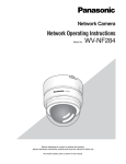
Network Interface Unit
Network Operating Instructions
Model No.
OPERATE
WJ-NT314
LINK RC
V SND
Network
Interfac
e Unit W
J-NT31
4
Before attempting to connect or operate this product,
please read these instructions carefully and save this manual for future use.
CONTENTS
Preface ..................................................................................................................................... 3
About these operating instructions ....................................................................................... 3
Trademarks and registered trademarks ............................................................................... 3
Viewer Software ................................................................................................................... 3
Monitor Images on a PC ........................................................................................................... 4
Monitor images from a single camera .................................................................................. 4
Monitor images from multiple cameras ................................................................................ 8
Action at an Alarm Occurrence ................................................................................................. 9
About the image recognition function ....................................................................................... 10
About "Live" page when AVMD is activated ......................................................................... 11
Transmit Images onto an FTP Server ...................................................................................... 12
Transmit an alarm image at an alarm occurrence (Alarm image FTP transmission) ........... 12
Transmit images at a designated interval or period (FTP periodic transmission) ................ 12
Save images on the SD memory card when failed to transmit images by the FTP
periodic transmission function .............................................................................................. 13
About the Network Security of This Unit ................................................................................... 15
Equipped security functions ................................................................................................. 15
Display the Setup Menu and Configure the Settings of the Unit using a PC ............................ 16
How to display the setup menu ............................................................................................ 16
How to operate the setup menu ........................................................................................... 17
Configure the basic settings of the unit [Basic setup] ........................................................... 20
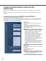
Configure the settings relating to images and audio [Camera setup] ................................... 26
Configures the multi-screen settings [Multi-screen setup] .................................................... 33
Configure the AVMD settings [Video analytics setup] .......................................................... 34
Configure the alarm settings [Alarm setup] .......................................................................... 40
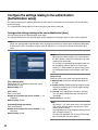
Configure the settings relating to the authentication [Authentication setup] ......................... 46
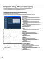
Configure the settings of the servers [Server setup] ............................................................ 48
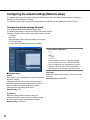
Configuring the network settings [Network setup] ................................................................ 50
Maintenance of the unit [Maintenance] ................................................................................ 57
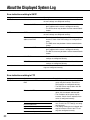
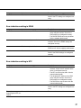
About the Displayed System Log ............................................................................................. 60
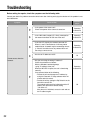
Troubleshooting ........................................................................................................................ 62
2
Preface
About these operating instructions
There are 2 sets of operating instructions for the WJ-NT314 as follows.
• Operating Instructions (Book)
• Network operating instructions (PDF)
These operating instructions contain descriptions of how to operate this product using a PC via a network and of
how to configure the settings.
Refer to the operating instructions for descriptions of how to install this product and of how to connect to a network.
Adobe® Reader® is required to read these operating instructions (PDF). When the Adobe Reader is not installed on
the PC, download the latest Adobe Reader from the Adobe web site and install it.
Trademarks and registered trademarks
• Microsoft, Windows, Internet Explorer, ActiveX, and DirectX are either registered trademarks or trademarks of
Microsoft Corporation in the United States and/or other countries.
• Adobe and Reader are either registered trademarks or trademarks of Adobe Systems Incorporated in the United
States and/or other countries.
• SD logo is a trademark.
• Other names of companies and products contained in these operating instructions may be trademarks or registered trademarks of their respective owners.
Viewer Software
• Images will not be displayed when the viewer software "Network camera View3" is not installed on the PC. Install
the viewer software from the provided CD-ROM.
• The viewer software used on each PC should be licensed individually. Refer to your dealer for the software
licensing.
3
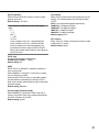
Monitor Images on a PC
The following are descriptions of how to monitor images from the unit on a PC.
Monitor images from a single camera
Step 1
Start up the web browser.
Step 2
Enter the IP address designated using the Panasonic IP
setup software in the address box of the browser.
(Example: http://192.168.0.10/)
Important:
• When the HTTP port number is changed from "80",
enter "http://IP address of the unit +: (colon) + port
number" in the address box of the browser, for
example, "http://192.168.0.11:8080".
• When the PC is in a local network, configure the
web browser to bypass the proxy server for the local
address.
Step 3
Press the [Enter] key on the keyboard.
→ The "Live" page will be displayed.
Important:
Follow the instructions on page 69 when the message is displayed on the information bar of the
browser.
Notes:
• When "ON" is selected for "User Authentication", the
authentication window will be displayed before displaying live images for the user name and password
4
entries. The default user name and password are as
follows.
User name: admin
Password: 12345
When accessing the unit without changing the
default password, the pop-up window saying that it
is recommended to change the password will be displayed.
To enhance the security, change the password for
the user "admin". It is recommended to change this
password periodically. (☞ page 46)
• When "Unicast port (AUTO)" or "Unicast port (MANUAL)" is selected for "Transmission type" (☞ page
28), up to 8 users per channel (up to 16 users for the
total of all the channels) can access the unit concurrently. Depending on the set values for "Total bit
rate" and "Max bit rate (per 1 client)", the maximum
concurrent access number may be limited. When 8
users have been concurrently accessing already, the
access limit message will be displayed for users who
accessed subsequently.
• When "ON" is selected for "MPEG-4 transmission"
(☞ page 24), an MPEG-4 image will be displayed.
When "OFF" is selected, a JPEG image will be displayed. It is possible to display JPEG image even
when "ON" is selected for "MPEG-4 transmission".
In this case, the refresh interval will be lowered to
approx. half the set value.
<Refresh interval (JPEG)>
When "ON" is selected for "MPEG-4 transmission"
JPEG (VGA): 15 fps
JPEG (QVGA): 60 fps
These are the total maximum values of all the channels.
The refresh interval may be longer depending on a
network environment, PC spec, photographic subject, access traffic, etc.
Important:
When displaying multiple MPEG-4 images on a PC,
images may not be displayed depending on the performance of the PC.
Refer to the next page for further information about the
"Live" page.
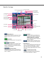
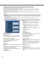
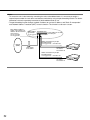
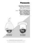
About the "Live" page
!9 Full screen button
!8 Alarm occurrence indication button
!7 Camera title
!6 Unit title
@0 One shot button
@1 Mic input button
@2 Audio output button
q [Setup] button
@3 Time and date
w [Live] button
e [1] to [4] buttons
r Multi-screen buttons
t Image type buttons
@4 Main area
!4 Frame
y AUX buttons
!5 Track
!2 BRIGHTNESS buttons
u B/W button
!3 Preset
i ZOOM buttons
!0 AUTO MODE
!1 Control pad/buttons
o FOCUS buttons
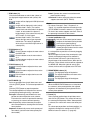
q
[Setup] button (*1)
Click this button to display the setup menu. The button will turn green and the setup menu will be displayed.
w
[Live] button
The button will turn green and the "Live" page will be
displayed.
e
[1] to [4] buttons
Click this button to display the "Live" page. The button will turn green and the "Live" page will be displayed. It is possible to select a desired channel by
clicking the [1] to [4] buttons.
r
Multi-screen buttons
Images from multiple cameras can be displayed on
a multi-screen by registering cameras on the setup
menu. (☞ page 8)
t Image type buttons
: The letters "MPEG-4" on the button will
turn green and an MPEG-4 image will be
displayed. When "OFF" is selected for
"MPEG-4 transmission" on the setup
menu, the [MPEG-4] button will not be displayed. (☞ page 27)
: The letters "JPEG" on the button will turn
green and JPEG image will be displayed.
y AUX buttons (*2)
Select 1 (AUX1) to (AUX3) from the pull-down menu
and click the [OPEN/CLOSE] button. (☞ page 43)
AUX1 and AUX2 are auxiliary outputs of camera.
AUX3 is the auxiliary output from the AUX 1 terminal
of this unit.
: The AUX connector will open.
: The AUX connector will close.
It is possible to change the names of AUX buttons
on the "Alarm setup" page. (☞ page 43)
5
u B/W button (*2)
Click the desired button to switch color (colour) of
the displayed images between color (colour) and
B/W.
: Images will be displayed in B/W (black and
white).
: Images will be displayed in color (colour).
: Activates Auto 1 mode. (The camera
selects black and white mode if the picture
is dark, or color mode if the picture is
bright enough.) If the camera has only one
AUTO mode, click this button.
: Activates Auto 2 mode. (The camera
detects the light source type to prevent
malfunction. This setting is applicable
when using a near-infrared light source in
a dark place.)
i ZOOM buttons (*2)
: Click this button to adjust the zoom ratio to
the WIDE side.
: Click this button to set the zoom ratio to
x1.0.
: Click this button to adjust the zoom ratio to
the TELE side.
o FOCUS buttons (*2)
: Click this button to adjust the focus automatically.
: Click this button to adjust the focus to the
NEAR side.
: Click this button to adjust the focus to the
FAR side.
!0 AUTO MODE (*2)
Select an operation from the pull-down menu and
click the [START] button. The selected operation will
start.
Click the [STOP] button to stop the operation.
The selected operation will stop when the camera
(panning/tilting/zooming/focusing) is operated.
Auto pan: Automatically pans between the start
position and the end position set in advance.
Even when the camera is operated for zooming
or focusing, the camera continues panning.
Sort: Sequentially switches between preset positions counterclockwise, starting from the camera
home position.
Sequence: Automatically moves to the preset positions orderly (start from the lowest preset position number).
6
Patrol: Operates the camera in accordance with
patrol function settings.
Auto track: Performs auto track when the camera
supports auto track (AUTO TRACK).
Notes:
• To activate "Auto pan", "Sort", "Sequence", or
"Patrol", it is required to perform the settings on the
SETUP MENU of camera in advance. (☞ page 28)
• To check if the camera supports auto track, refer to
the operating instructions of the camera.
!1 Control pad/buttons (*2)
: Left-click on the control pad or buttons
to adjust the horizontal/vertical position
of the camera (panning/tilting).
Panning/tilting speed will be faster if a
clicked point gets farther from the center
point of the control pad.
It is also possible to pan/tilt the camera by dragging
the mouse.
When the upper half area of the control pad is rightclicked, the displayed image will be zoomed in.
When the lower half area is right-clicked, the displayed image will be zoomed out on. When the left
half area is right-clicked, the focus will be adjusted to
the NEAR side. When the right half area is rightclicked, the focus will be adjusted to the FAR side.
!2 BRIGHTNESS buttons (*2)
: The displayed image will be darker.
: The adjusted brightness will return to the
default brightness.:
: The displayed image will be brighter.
Note:
When the BRIGHTNESS buttons are clicked while
the camera is at the preset position, the adjusted
brightness will automatically be registered for the
current preset position.
!3 Preset (*2)
Select a preset position from the pull-down menu
and click the [GO] button. The camera will move to
the selected preset position. When "Home position"
is selected, the camera will move to the home position.
To activate preset positions and home position, it is
required to configure the settings on the SETUP
MENU of camera in advance. (☞ page 28)
!4 Frame
Displays/hides the frame when a person is detected.
Refer to page 11 for further information.
!5 Track
Displays/hides the track of motion made by the
detected person.
Refer to page 11 for further information.
!6 Unit title
The unit title entered for "Unit title" on the [Basic] tab
will be displayed. (☞ page 20)
!7 Camera title
The camera title set for [Camera title] will be displayed. (☞ page 20)
!8
Alarm occurrence indication
button (*2)
This button will be displayed at an alarm occurrence,
and the channel of alarm occurrence (one of [1] to
[4] buttons) will light. When the button is clicked, the
button will disappear and the alarm output connector
will be reset. (☞ page 40)
!9
Full screen button
Images will be displayed on a full screen. To return
to the "Live" page, press the [Esc] key. When displaying images on a full screen, the audio output
button will become unavailable.
@0
One shot button
Click this button to take a picture (a still picture). The
picture will be displayed on a newly opened window.
When right-clicking on the displayed image, the popup menu will be displayed. The displayed image can
be saved on the PC by selecting "Save" from the
pop-up menu.
The displayed image can be printed from the printer
by selecting "Print" from the pop-up menu. The
newly opened window will be closed by clicking the
"Close" button.
@1
Mic input button (*3)
Turns on/off the audio reception (hear audio from
the unit on a PC). This button will be displayed only
when "Mic input" or "Interactive" is selected for
"Audio mode" on the setup menu. (☞ page 31)
When this button is clicked, the button will turn into
the
button and audio from the unit will not be
heard.
Notes:
• When this button is clicked, audio from the PC will
be turned off.
When closing the window, click the button again to
turn on the audio.
• Audio reception is turned on for CH 1 only.
@2
Audio output button (*3)
Turns on/off the audio transmission (play audio from
the PC on the unit speaker). This button will be displayed only when "Audio output" or "Interactive" is
selected for "Audio mode" on the setup menu.
(☞ page 31)
The button blinks while the audio transmission is
being carried out.
When this button is clicked, the button will turn into
the
button and audio from the PC will not be
heard.
Notes:
• When a user is using the audio transmission function, the mic input button and the audio output button
will be inoperable for the other users.
• Possible duration of audio transmission is up to 5
minutes per transmission. When 5 minutes have
passed, the audio transmission function will be canceled and the audio reception function will automatically be turned on. To turn the audio transmission
function on, click the audio output button again.
• Audio transmission is turned on for CH 1 only.
@3 Time and date
Current time will be displayed in the set date/time
display format (☞ page 20).
@4 Main area (*2)
Images from the camera will be displayed in this
area.
Click a desired point in the main area on the "Live"
page that is to be the centre of the angle of view.
The camera moves to adjust the position in order to
set the clicked point as the centre.
Note:
When using this function, set "PROPO.P/T" of camera to ON. (☞ page 30)
The following cameras are available for the function.
WV-CS950 series, WV-CW960 series, WV-CW970
series (as of August 2007)
7
*1 Operable by only users and hosts whose access
level is "1. Administrator"
*2 Only operable by users and hosts whose access
level is "1. Administrator" or "2. Camera control"
when "ON" is selected for "User authentication"
(☞ page 46) and "Host authentication" (☞ page 47).
*3 Operable by users and hosts who belong to the
access level selected for "Authentication" on the
[Audio] tab of the "Camera setup" page. (☞ page 32)
Refer to page 46 for further information about the
access level.
Important:
It is impossible to display images and to receive/
transmit audio between the unit and the PC when
the viewer software "Network Camera View3" is not
installed on the PC. (Refer to the operating instructions for descriptions of how to install.)
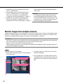
Monitor images from multiple cameras
Images from multiple cameras can be displayed on a multi-screen. Images from 4 cameras can be displayed simultaneously. To display images on a multi-screen, it is necessary to register cameras in advance. 4 cameras can be
registered as a group and up to 4 groups (16 cameras) can be registered. (☞ page 33)
Important:
• Select "OFF" for both the user authentication and the host authentication of the network device to be registered.
• Only JPEG images can be displayed on a multi-screen. Audio will not be heard.
• Multi-screen is the function that is available using this unit.
When the power is turned off or the LAN cable is disconnected while displaying images, displaying images on a
multi-screen will become unavailable.
Step 1
Click one of the multi-screen buttons.
→ Images from the registered cameras will be displayed
on a 4-split screen.
q To display images on a single screen, click the [1]
button or [Live] button.
w Click a camera title. Live images from the camera
corresponding to the clicked camera title will be displayed on the "Live" page of the newly opened window.
q
8
w
Action at an Alarm Occurrence
The alarm action will be performed when the following alarm occur.
Alarm type
Terminal alarm: When connecting an alarm device such as a sensor to the connector terminal (Alarm Input
No. 1 to 4) on the rear of the unit, the alarm action (unit action at an alarm occurrence) will be performed
when the connected alarm device is activated. Alarm action to be performed differs depending on the settings
configured on the [Alarm] tab. (☞ page 41)
Camera site alarm: When a camera connected to a VIDEO IN connector detects an alarm by alarm sensors or
cameras' motion detectors, etc., and the unit receives the alarm input signal from the camera, the alarm
action will be performed. (☞ page 41)
Video loss: When the loss of video input signals is detected due to coaxial cable disconnections or camera troubles, the alarm action will be performed. (☞ page 41)
Command alarm: When a Panasonic alarm protocol is received from the connected device via a network, the
alarm action will be performed. (☞ page 41)
AVMD (Advanced Video Motion Detector): When a person is detected in the image from a camera connected
to a VIDEO IN connector, the alarm action will be performed. (☞ page 40)
Action at an Alarm Occurrence
Display the alarm occurrence indication button on the "Live" page (☞ page 5).
The alarm occurrence indication button will be displayed on the "Live" page at an alarm occurrence.
Note:
The alarm occurrence indication button will be refreshed in 30 seconds intervals. For this reason, it may take a
maximum of 30 seconds until the alarm occurrence indication button is displayed on the "Live" page at an alarm
occurrence.
Notify of alarm occurrences to the device connected to the alarm connector
It is possible to output signals from the alarm connector on the rear of the unit and sound the buzzer when an alarm
occurs. The settings for the alarm output can be configured on the [Alarm] tab of the "Alarm setup" page.
(☞ page 43)
Transmit an image onto a server automatically
An alarm image can be transmitted at an alarm occurrence to the server designated in advance. The settings
required to transmit an alarm image to a server can be configured in the "Alarm image setup" section of the [Alarm]
tab of the "Alarm setup" page (☞ page 42) and the [FTP] tab of the "Server setup" page (☞ page 49).
Notify of alarm occurrences by e-mail
Alarm mail (alarm occurrence notification) can be sent at an alarm occurrence to the e-mail addresses registered in
advance. Up to 4 addresses can be registered as recipients of the alarm mail. The settings for alarm mail can be
configured in the "E-mail notification setup" section of the [Notification] tab of the "Alarm setup" page (☞ page 44)
and the [Mail] tab of the "Server setup" page (☞ page 48).
Notify of alarm occurrences to the designated IP addresses (Panasonic alarm protocol)
This function is available only when Panasonic device, such as the network disk recorder, is connected to the system. When "ON" is selected for "Panasonic alarm protocol", the connected Panasonic device will be notified that the
unit is in the alarm state. The settings for Panasonic alarm protocol can be configured on the [Notification] tab of the
"Alarm setup" page. (☞ page 44)
9
About the image recognition function
AVMD, which is one of the image recognition functions, are featured in this unit.
It is possible to detect moving, abandoned, or removed objects in the shooting area by setting the detection program
in advance. (☞ page 34)
When an abandoned or removed object is detected, the frame and track, are displayed on the live images. (☞ page
12)
Auto track for the detected object is also possible using another analog camera. (☞ page 41)
It is also possible to specify the range of people’s motion and the size of detected object by setting the detection
depth.
AVMD can be activated for up to 2 channels at the same time.
Intruder detection
The motion of object is detected in the shooting area of the channel for which the AVMD is activated.
Up to 8 objects can be detected simultaneously per channel. It is impossible to recognize 9 objects or more.
(Depending on the size of moving object, less than 8 objects can be detected.)
The detection status will be canceled when the moving object goes out of the shooting area.
By setting the intruder detection area (☞ page 34), it is possible to activate an alarm when a moving object goes into
the area. (To prevent false notifications, it is necessary for the object to be detected as a moving object for 2 seconds or more.)
Detection of abandoned or removed objects
By setting the detection area of object abandonment / removal (☞ page 34) in the shooting area of the channel for
which the AVMD is activated, it is possible to activate an alarm when an object is abandoned in the area or removed
from the area. (To prevent false notifications, it is necessary for the object to be detected as an abandoned or
removed object for 20 seconds or more.)
Up to 8 objects can be detected simultaneously per channel. It is impossible to recognize 9 people or more.
The detection status will be canceled when around 40 seconds have passed after the detection.
Important:
AVMD will be activated even after the camera moves or is moving from the selected preset position. To prevent
false notifications, it is recommended not to move the camera connected to the channel for which the AVMD is
activated.
About AVMD (Advanced Video Motion Detection)
AVMD of this unit is the image recognition function that detects motion based on the luminance transition in a designated area. Under the following circumstances, AVMD may not be activated properly.
• There is no difference in luminance level between the moving object and background.
• Luminance level of image is too low (During nighttime, etc.)
• Movement of object is too fast or too slow.
• Object is too big or too small.
• Luminance level of shooting area is subject to change (outdoors, by the window, etc.)
• Outside light (sunlight, headlights, etc.) enters the shooting area.
• Fluorescent light is flickering.
• Depth of object is too long.
• Dirt, drip, or splash is on the dome cover of camera.
• Object is moving directly toward the camera.
• Too many objects are moving.
• Camera is shaking.
10
• Weather condition is extremely poor.
When setting AVMD, check the performance during both daytime and nighttime after setting the detection area,
according to the installation place of camera and the assumed motion of object. If the AVMD is activated improperly
or not activated even after the setting, use a sensor.
Luminance level affects detection of abandoned or removed objects. It is recommended to use this unit in a room
where luminance level is stable.
While the detected object exists in the shooting area, the alarm occurrence will be notified every 5 seconds. The
alarm occurrence will also be notified by e-mail and Panasonic alarm protocol each time.
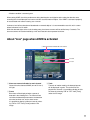
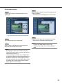
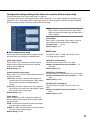
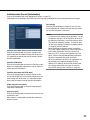
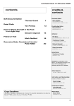
About "Live" page when AVMD is activated
q Alarm occurrence indication for each channel
w Frame
e Track
q Alarm occurrence indication for each channel
Channel that has detected AVMD (one of CH1 to 4)
will light.
w Frame
Blue frame will be displayed when a person is
detected in the shooting area. The frame will turn
red when the detected person enters the detection
area that has been set, and an alarm occurs.
It is possible to display or hide the frame by selecting "ON" or "OFF" from [Frame] under the live
image.
e Track
The track of motion made by the detected person
will be displayed in green. The track will be displayed for 3 seconds. It is possible to display or hide
the frame by selecting "ON" or "OFF" from [Track]
under the live image.
11
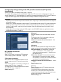
Transmit Images onto an FTP Server
Images can be transmitted to an FTP server. By configuring the following settings, transmission of images captured
at an alarm occurrence or captured at a designated interval to an FTP server will become available.
Important:
When using this function, set the user name and the password to access the FTP server to restrict users who
can log into the FTP server.
Transmit an alarm image at an alarm occurrence (Alarm image
FTP transmission)
An alarm image can be transmitted at an alarm occurrence to the FTP server. To transmit alarm images to an FTP
server, it is necessary to configure the settings in advance.
The settings for the FTP server can be configured on the [FTP] tab of the "Server setup" page. (☞ page 49)
The alarm image FTP transmission function can be turned on/off on the [Alarm] tab of the "Alarm setup" page.
(☞ page 42)
Note:
Depending on the network traffic, number of the transmitted images may not reach the set number of images to
be transmitted.
Transmit images at a designated interval or period (FTP periodic
transmission)
Images can be transmitted at a designated interval or period. To transmit images at a designate interval or period, it
is necessary to configure the settings in advance.
The settings for the FTP server to which images are to be transmitted can be configured on the [FTP] tab of the
"Server setup" page. (☞ page 49)
On the [FTP] tab of the "Network setup" page, the FTP periodic transmission function can be turned on/off, and the
settings relating to schedules (periods) can be configured. (☞ page 55)
Notes:
• Depending on the network line speed or the network traffic, images may not be transmitted at the exact designated interval or period.
• When "ON" is selected for both of the alarm image FTP transmission function and the FTP periodic transmission
function, the alarm image FTP transmission function will be given priority over the FTP periodic transmission
function. For this reason, images may not be transmitted at the exact designated interval or period if alarms
occur frequently.
12
Save images on the SD memory card when failed to transmit
images by the FTP periodic transmission function
Images that have failed to transmit using the FTP periodic transmission can be saved automatically on the SD memory card.
When using the "SD memory REC" function of a Panasonic’s network disk recorder, select "OFF" for the "FTP periodic transmission" function. (☞ page 55) Refer to the operating instructions of network disk recorder for further information.
We make no guarantee for any damages of files on the SD memory card incurred by malfunction or error occurrence
in files saved on the SD memory card regardless of what the cause may be.
Possible capacity of images that can be saved on the SD memory card will be different depending on the number of
selected channels (☞ page 26), image capture size (☞ page 27), and image quality (☞ page 27).
When using an SD memory card, it is recommended to check the recording condition and select "5 sec" or longer for
"Interval" on the [FTP] tab. (☞ page 55)
Save images on the SD memory card
By selecting "Use" for "About SD memory card" on the [SD memory card] tab of the "Basic setup" page (☞ page 23),
saving images which had been failed to transmit to the FTP server using the FTP periodic transmission function will
become available.
Obtain images on the SD memory card
Step 1
Access the unit using the Windows® command prompt or FTP client software.
→ The window with the user name and password entry fields will be displayed.
On the FTP server, only access the "sd_data" directory.
Note:
When accessing this unit via the FTP server, select "Allow" for "FTP access" on the [Network] tab of the
"Network setup" page. (☞ page 51)
Step 2
Enter the user name whose access level is "1. Administrator" and its password.
→ Log in the unit.
Note:
The default user name with the access level "1. Administrator" and its password are as follows.
User name: admin
Password: 12345
To enhance the security, it is recommended to change the password for the administrator periodically.
(☞ page 46)
13
Step 3
Move the current directory to "sd_data" and obtain images.
Note:
• When logging in the unit, each directory will be displayed. Images on the SD memory card can be found in the
"sd_data" directory. Move to the "sd_data" directory and obtain images.
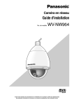
<Directory structure of "sd_data">
sd_data
Directory
ftp
:
:
:
:
log
Directory
(year/month/day)
Directory
(hour/minute)
070101
0123
070102
:
:
:
:
An image failed to transmit by the FTP
periodic transmission function
(Ex. img_010701010123000.jpg)
↑ The image will be saved here.
← Destination of logs to be saved
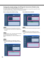
To obtain the image (img_0107010101230000.jpg) using the Windows command prompt
q Enter "c:\>ftp 192.168.0.10" and press the [Enter] key.
FTP connection will be established with "192.168.0.10".
w Log in by entering the user name and the password.
e Enter "ftp> cd sd_data/ftp/070101/0123" and press the [Enter] key.
→ The current directory will be "sd_data/070101/0123".
r The transfer mode will be set to the binary mode. Enter "ftp> bin" and press the [Enter] key.
t Obtain the image. Enter "ftp> get img_0107010101230000.jpg" and press the [Enter] key.
→ The image will be obtained.
y Log out by entering "ftp> bye" and press the [Enter] key.
→ You will log out of the "FTP" directory.
• It is possible to delete images on the SD memory card using the Windows command prompt, etc.
14
About the Network Security of This Unit
Equipped security functions
The following security functions are featured in this unit.
q Access restrictions by the host authentication and the user authentication
It is possible to restrict users from accessing the unit by setting the host authentication and/or the user authentication to on. (☞ pages 46 and 47)
w Access restrictions by changing the HTTP port
It is possible to prevent illegal access such as port scanning, etc. by changing the HTTP port number.
(☞ page 51)
Note:
When user authentication (authentication error) has failed to pass 8 times (6 times when clicking the [Go] button
of the browser) within 30 seconds using the same IP address (PC), access to the unit will be denied for a while.
Important:
Design and enhance security countermeasures to prevent leakage of information such as image data, authentication information (user name and password), alarm mail information, FTP server information, DDNS server
information, etc.
15
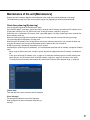
Display the Setup Menu and Configure the Settings of the Unit using a PC
The settings of the unit can be configured on the setup menu.
The setup menu is only operable by users whose access level is "1. Administrator".
How to display the setup menu
Step 1
Display the "Live" page. (☞ page 4)
Step 2
Click the [Setup] button on the "Live" page.
→ The window with the user name and password entry
fields will be displayed.
Step 3
Click the [OK] button after entering the user name and
the password. (Refer to page 4 for the default user
name and password.)
→ Click this button to display the setup menu.
Refer to the next page for further information about
this menu.
16
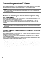
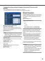
How to operate the setup menu
Important:
When there are two [SET] buttons (or [REG] buttons) or more on the page, click the respective button to the edited setting item.
<Example>
A
A-1
Menu button
Setup page
Step 1
Click the desired button in the frame on the left of the
window to display the respective setup menu.
When there are tabs at the top of the setup page displayed in the frame on the right of the window, click the
desired tab to display and configure the setting items
relating to the name of the tab.
B
B-1
When completing the setting items in field A, click
the [SET] button below field A (A-1). The edited setting items in field A will not be applied unless the
[SET] button below field A (A-1) is clicked.
In the same manner as above, click the [SET] button
below field B (B-1) when completing the setting
items in field B.
Step 2
Complete each setting item displayed in the frame on
the right of the window.
Step 3
After completing each setting item, click the [SET] button to apply them.
17
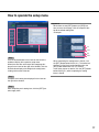
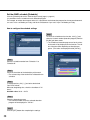
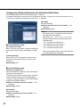
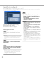
About the operation window
!2 Status display
area
q [Live] button
w [Basic Setup] button
e [Camera setup] button
r [Multi-screen setup] button
!3 Setup page
t [Video analytics setup]
button
y [Alarm setup] button
u [Authentication setup]
button
i [Server setup] button
o [Network setup] button
!0 [Maintenance] button
!1 [Help] button
q
[Live] button
The "Live" page will be displayed.
w
[Basic setup] button
Click this button to display the "Basic setup" page.
The basic settings such as time and date and camera title, and the settings relating to the NTP server
and the SD memory card can be configured on the
"Basic setup" page. Refer to page 20 for further
information.
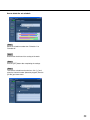
e
r
18
[Camera setup] button
Click this button to display the "Camera setup" page.
The settings relating to JPEG/MPEG-4 images and
camera operation can be configured on the "Camera
setup" page. Refer to page 26 for further information.
[Multi-screen setup] button
Click this button to display the "Multi-screen setup"
page. The cameras to be used for the multi-screen
display can be registered on the "Multi-screen setup"
page. Refer to page 33 for further information.
t
[Video analytics setup] button
Click this button to display the "Video analytics
setup" page.
The detection program and schedule for AVMD can
be configured on this page.
Refer to page 34 for further information.
y
[Alarm setup] button
Click this button to display the "Alarm setup" page.
The settings relating to alarm occurrences such as
settings for the alarm action at an alarm occurrence
and the alarm occurrence notification can be configured on the "Alarm setup" page. Refer to page 40 for
further information.
u
[Authentication setup] button
Click this button to display the "Authentication setup"
page. The settings relating to the authentication
such as users and PCs restrictions for accessing the
unit can be configured on the "Authentication setup"
page. Refer to page 46 for further information.
i
[Server setup] button
Click this button to display the "Server setup" page.
The settings relating to the mail server and the FTP
server to which the unit accesses can be configured
on the "Server setup" page. Refer to page 48 for further information.
o
[Network setup] button
Click this button to display the "Network setup" page.
The network settings and the settings relating to
DDNS (Dynamic DNS), SNMP (Simple Network
management Protocol) and FTP (File Transfer
Protocol) can be configured on the "Network setup"
page. Refer to page 50 for further information.
!0
[Maintenance] button
Click this button to display the "Maintenance" page.
System log check, firmware upgrade and initialization of the setup menu can be carried out on the
"Maintenance" page. Refer to page 57 for further
information.
!1
[Help] button
Click this button to display the "Help" page.
!2 Status display area
The name of the unit whose settings currently being
configured, and date and time will be displayed.
!3 Setup page
Pages of each setup menu will be displayed. There
are tabs for some setup menus.
19
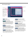
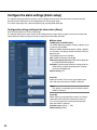
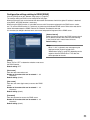
Configure the basic settings of the unit [Basic setup]
The basic settings such as time and date and unit name, and the settings relating to the NTP server and the SD
memory card can be configured on the "Basic setup" page.
The "Basic setup" page has 4 tabs of the [Basic] tab, the [NTP] tab, [SD memory card] tab, and the [RS485 setup]
tab.
Configure the basic settings [Basic]
Click the [Basic] tab on the "Basic setup" page.
The settings such as the unit name, time and date, etc. can be configured on this page.
[Time display]
Select the time display format from "12-hours", "24hours" and "OFF". Enter the current hour reflecting this
setting when entering the current time and date for
"Time & date setup".
Default setting: 12-hours (NTSC model)
24-hours (PAL model)
[Unit title]
Enter the title of the unit. Click the [SET] button after
entering the title of the unit. The entered title will be
displayed in the status display area.
Number of characters that can be entered: 0 - 20
characters
Default setting: WJ-NT314
[Camera title]
Enter the names of the cameras connected to VIDEO IN
connectors. The entered names will be displayed in the
upper left area.
Number of characters that can be entered: 0 - 20
characters
Default setting: Name of CH1: WJ-NT314 CH1
Name of CH2: WJ-NT314 CH2
Name of CH3: WJ-NT314 CH3
Name of CH4: WJ-NT314 CH4
[Time & date setup]
Enter the current time and date. When "12-hours" is
selected for "Date/time display format", "AM" or "PM"
can be selected.
Available value: 01/01/2006 00: 00: 00 12/31/2035 23: 59: 59
20
[Date/time display format]
Select a date/time display format.
When "04/01/2007 13:10:00" is set for "Time and date
setup" after selecting "24-hours" for "Date/time display
format", time and date will be displayed as follows
respectively.
DD/MM/YYYY: 01/04/2007 13:10
MM/DD/YYYY: 04/01/2007 13:10
DD/Mmm/YYYY: 01/Apr/2007 13:10
YYYY/MM/DD: 2007/04/01 13:10
Mmm/DD/YYYY: Apr/01/2007 13:10
Default setting: Mmm/DD/YYYY (NTSC model)
DD/MM/YYYY (PAL model)
[Daylight saving (Summertime)]
Select "ON" or "OFF" to determine whether or not to
apply daylight saving time. Select "ON" or "OFF" to
determine whether or not to apply daylight saving time.
ON: Applies summer time. An asterisk (*) will be displayed on the left side of the displayed time and
date.
OFF: Does not apply summer time.
Default setting: OFF
[Alarm status update mode]
Select an interval to notify the unit status (alarm status,
audio status, etc.) from the following.
When the status of the unit changes, the alarm occurrence indication button, the mic input button, or the
audio output button will be displayed to notify of the unit
status.
Polling (30 sec): Updates the status each 30 seconds
and provide notification of the unit status.
Real time: Provide notification of the unit status when
the status has changed. (Except the alarm occurrence indication button)
Default setting: Real time
Note:
Depending on the network environment, notification
may not be provided in real time.
[Alarm status port]
When selecting "Real time" for "Alarm status update
mode", designate a port number to which the status
change notification is to be sent.
Available value: 1 - 65535
Default setting: 31004
21
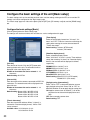
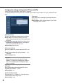
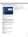
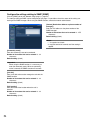
Configure the settings relating to the NTP server [NTP]
Click the [NTP] tab on the "Basic setup" page. (☞ page 20)
The settings relating to the NTP server such as the NTP server address, port number, etc. can be configured on this
page.
[Time zone]
Select a time zone according to the location where the
unit is in use.
Default setting: (GMT) Greenwich Mean Time: Dublin,
Edinburgh, Lisbon, London
[Time adjustment]
Select the time adjustment method from the following.
Manual setup: Time set on the [Basic] tab on the
"Basic setup" page will be used as the standard time
of the unit.
Synchronization with NTP server: Time automatically
adjusted by synchronizing with NTP server will be
used as the standard time of the unit.
Default setting: Manual setup
[NTP server address]
Enter the IP address or the host name of the NTP server.
Number of characters that can be entered: 1 - 128
characters
Default setting: (blank)
Important:
When entering the host name for "NTP server
address", it is necessary to configure the DNS settings on the [Network] tab of the "Network setup"
page. (☞ page 51)
[NTP port]
Enter a port number to be used for the NTP server.
Available port number: 1 - 65535
Default setting: 123
[Synchronization interval]
Select an interval (1 - 24 hours: in 1 hour intervals) of
synchronization with the NTP server.
Default setting: 1 hour
22
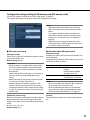
Configure the settings relating to SD memory card [SD memory card]
Click the [SD memory card] tab on the "Basic setup" page. (☞ page 20)
The settings relating to the SD memory card can be configured on this page.
Note:
Notification will be provided when the remaining
space of the SD memory card reached the values
above.
For example, notification will be provided for the
destination IP address when the remaining space
reaches 50 % or less when "50%" is selected. (☞
page 45)
Notification may not always be made at the very
moment when the remaining space of the SD memory card has reached each value.
■ SD memory card setup
■ Information about SD memory card
[SD memory card]
Select "Use" or "Not use" to determine whether or not to
use the SD memory card.
Default setting: Not use
[SD memory card]
Available size and the total size of the SD memory card
will be displayed.
Depending on the state of the SD memory card, the size
indications will differ as follows.
Important:
• When the power is shut down while saving images
on the SD memory card because of power failure,
etc., SD memory card or the contents of card may
be destroyed.
(When using an SD memory card, it is recommended to use an UPS (uninterruptible power equipment).)
• Before removing the SD memory card from the unit,
it is necessary to select "Not use" first.
• Before inserting a SD memory card into the SD
memory card slot, turn the power of the unit off. (☞
Operating Instructions) After inserting the SD memory card, it is necessary to select "Use" to use the SD
memory card.
[Notification of remaining]
When the "Panasonic alarm protocol" function is used to
provide notification of the remaining space of the SD
memory card, select a level to be notified at from the following.
50 %/20 %/10 %/5 %/2 %
Default setting: 50 %
Content
----------KB/-----------KB
Description
No SD memory card is
inserted.
Failed to obtain available
size due to error, etc.
**********KB/**********KB The SD card memory is
unformatted, or locked, etc.
Note:
When the available size reached "0 KB", images will
not be saved on the SD memory card.
When the notification function is on, a notification
mail will be sent to the registered addresses when
the SD memory card becomes full. (☞ page 45)
[Format]
To format the SD memory card, click the [Execute] button.
23
Important:
• Before formatting the SD memory card, it is necessary to select "Use" for "SD memory card" on the
[SD memory card] tab of the "Basic setup" page
(☞ page 55) and "OFF" for "FTP periodic transmission" on the [FTP] tab of the "Network setup" page
(☞ page 49).
• Format the SD memory card only by clicking the
[Execute] button on the setup menu. Otherwise, the
following functions using the SD memory card may
not work properly with this unit.
• Save/obtain images when failed to transmit to
the FTP server using the FTP periodic transmission function
• Save/obtain the system logs
• Save/obtain images recorded using the SD
memory recording function of Panasonic's network disk recorder.
• It is impossible to format the SD memory card in the
process of accessing, for example, when writing
images on the SD memory card or during the FTP
access.
• It is impossible to access the SD memory card in the
process of formatting.
• All data saved on the SD memory card will be deleted when the SD memory card is formatted.
• Do not turn the power of the unit off in the process of
formatting.
• After formatting the SD memory card, available size
may be smaller than the total size since the default
directory is automatically created in the SD memory
card. After formatting the SD memory card, available
size/total size will be refreshed when the window is
refreshed.
• Compatible SD memory card is as follows.
SD memory card manufactured by Panasonic
(64 MB, 128 MB, 256 MB, 512 MB, 1 GB, 2GB)
(SDHC memory card is not supported.)
• Depending on the remaining space of the SD memory card, it may take around 30 seconds to format the
card.
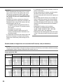
Possible number of images that can be saved on the SD memory card (as indications)
Important:
They are not actual numbers of images that can be saved on the SD memory card. Numbers will differ according
to photographic subject, settings relating to the SD memory card, etc.
Image capture size: VGA
Size of SD
memory card
Image quality
0 (Super fine)
1 (Fine)
2
3
4
2 GB Approx. 10 000 pics Approx. 14 000 pics Approx. 16 000 pics Approx. 18 000 pics Approx. 20 000 pics
1 GB Approx. 5 000 pics Approx. 7 000 pics Approx. 8 000 pics Approx. 9 000 pics Approx. 10 000 pics
512 MB Approx. 2 500 pics Approx. 3 500 pics Approx. 4 000 pics Approx. 4 500 pics Approx. 5 000 pics
256 MB Approx. 1 250 pics Approx. 1 750 pics Approx. 2 000 pics Approx. 2 250 pics Approx. 2 500 pics
Approx. 875 pics Approx. 1 000 pics Approx. 1 125 pics Approx. 1 250 pics
Approx. 625 pics
128 MB
Approx. 625 pics
Approx. 562 pics
Approx. 500 pics
Approx. 437 pics
Approx. 312 pics
64 MB
Size of SD
memory card
Image quality
5 (Normal)
6
7
8
9 (Low)
2 GB Approx. 22 000 pics Approx. 26 000 pics Approx. 28 000 pics Approx. 30 000 pics Approx. 32 000 pics
1 GB Approx. 11 000 pics Approx. 13 000 pics Approx. 14 000 pics Approx. 15 000 pics Approx. 16 000 pics
512 MB Approx. 5 500 pics Approx. 6 500 pics Approx. 7 000 pics Approx. 7 500 pics Approx. 8 000 pics
256 MB Approx. 2 750 pics Approx. 3 250 pics Approx. 3 500 pics Approx. 3 750 pics Approx. 4 000 pics
128 MB Approx. 1 375 pics Approx. 1 625 pics Approx. 1 750 pics Approx. 1 875 pics Approx. 2 000 pics
Approx. 937 pics Approx. 1 000 pics
Approx. 875 pics
Approx. 812 pics
Approx. 687 pics
64 MB
24
Image capture size: QVGA
Size of SD
memory card
Image quality
0 (Super fine)
1 (Fine)
2
3
4
2 GB Approx. 24 000 pics Approx. 26 000 pics Approx. 27 000 pics Approx. 28 000 pics Approx. 30 000 pics
1 GB Approx. 12 000 pics Approx. 13 000 pics Approx. 13 500 pics Approx. 14 000 pics Approx. 15 000 pics
512 MB Approx. 6 000 pics Approx. 6 500 pics Approx. 6 750 pics Approx. 7 000 pics Approx. 7 500 pics
256 MB Approx. 3 000 pics Approx. 3 250 pics Approx. 3 375 pics Approx. 3 500 pics Approx. 3 750 pics
128 MB Approx. 1 500 pics Approx. 1 625 pics Approx. 1 687 pics Approx. 1 750 pics Approx. 1 875 pics
Approx. 937 pics
Approx. 875 pics
Approx. 843 pics
Approx. 812 pics
Approx. 750 pics
64 MB
Size of SD
memory card
Image quality
5 (Normal)
6
7
8
9 (Low)
2 GB Approx. 32 000 pics Approx. 36 000 pics Approx. 38 000 pics Approx. 40 000 pics Approx. 42 000 pics
1 GB Approx. 16 000 pics Approx. 18 000 pics Approx. 19 000 pics Approx. 20 000 pics Approx. 21 000 pics
512 MB Approx. 8 000 pics Approx. 9 000 pics Approx. 9 500 pics Approx. 10 000 pics Approx. 10 500 pics
256 MB Approx. 4 000 pics Approx. 4 500 pics Approx. 4 750 pics Approx. 5 000 pics Approx. 5 250 pics
128 MB Approx. 2 000 pics Approx. 2 250 pics Approx. 2 375 pics Approx. 2 500 pics Approx. 2 625 pics
64 MB Approx. 1 000 pics Approx. 1 125 pics Approx. 1 187 pics Approx. 1 250 pics Approx. 1 312 pics
Configure the settings relating to the RS-485 port [RS485 setup]
Click the [RS485 setup] tab on the "Basic setup" page. (☞ page 20)
The settings relating to the RS-485 port such as the communication speed can be configured on this page.
[Parity check]
Select the parity check method for RS-485 port from the
following.
NONE: Parity check is not performed.
ODD: Parity check is performed for odd parity bits.
EVEN: Parity check is performed for even parity bits.
Default setting: NONE
[Stop bit]
Select "1 bit" or "2 bit" to determine the stop bit for the
RS-485 port.
Default setting: 1 bit
[Communication speed]
Select the communication speed for RS-485 port from
the following.
9600/19200/38400 bps
Default setting: 38400 bps
[Data bit]
Select "7 bit" or "8 bit" to determine the data bit for the
RS-485 port.
Default setting: 8 bit
25
Configure the settings relating to images and audio
[Camera setup]
The settings relating to JPEG/MPEG-4 images and camera operation can be configured on the "Camera setup"
page.
The "Camera setup" page has 4 tabs of the [JPEG/MPEG-4] tab, the [Camera] tab, [Audio] tab and the [Coaxial
setup] tab.
Configure the settings relating to JPEG/MPEG-4 image [JPEG/MPEG-4]
Click the [JPEG/MPEG-4] tab on the "Camera setup" page.
Configure the settings relating to JPEG/MPEG-4 image such as "Max bit rate (per 1 client)", "Image capture size",
"Image quality", etc. in this section. These settings are common among each channel. To configure each channel
setting individually, press [To individual setup] button.
[Total bit rate]
Select the total bit rate for data transmission from the
followings.
Unlimited/64 kbps/128 kbps/256 kbps/512 kbps/
1024 kbps/2048 kbps/4096 kbps/8192 kbps/16384 kbps
Default setting: Unlimited
Notes:
• When selecting "64 kbps", select "OFF" for "Audio
mode" on the "Audio" tab. (☞ page 31) Otherwise,
images cannot be transmitted correctly.
• When "64 kbps" or "128 kbps" is selected, do not
carry out the live-transmission of JPEG images and
the FTP periodic transmission simultaneously.
Otherwise, images cannot be transmitted correctly.
• Even when "Unlimited" is set for "Total bit rate",
image data whose total size is 20 Mpbs or more may
be destroyed during transmission.
• The actual total bit rate may be approx. twice the set
value when MPEG-4 transmission is carried out in
combination with JPEG transmission or FTP transmission.
[CH selection]
Select the channel number of VIDEO IN connector from
the following.
CH1 only/CH1-2/CH1-3/CH1-4
Default setting: CH1-4
Important:
The set values of JPEG setup and MPEG-4 setup
are common among each channel.
26
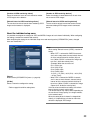
■ JPEG setup
[Refresh interval (JPEG)]
Select an interval to refresh the displayed JPEG image
from the following.
NTSC model: 0.1 fps/0.2 fps/0.33 fps/0.5 fps/1 fps/
2 fps/3 fps/5 fps */6 fps */10 fps */15 fps */30 fps *
Default setting: 3 fps
PAL model: 0.08 fps/0.17 fps/0.28 fps/0.42 fps/
0.83 fps/1.7 fps/2.5 fps/4.2 fps */5 fps */8.3 fps */
12.5 fps */25 fps *
Default setting: 2.5 fps
Notes:
• Depending on the setting value of "CH selection",
"MPEG-4 transmission", "Image capture size" of
JPEG setup, or "Image quality" of JPEG setup, the
refresh interval may be lower than the value when
the setting value with an asterisk (*) on the right is
selected. (☞ page 29)
• JPEG images are not encoded exceeding the setting
value of "Refresh interval (JPEG)". (At least 3 fps is
secured.)
When a connected device requests an exceeding
value, change the setting value of "Refresh interval
(JPEG)".
[Image capture size]
Select "VGA (640 x 480)" or "QVGA (320 x 240)" for the
image capture size of JPEG images.
Default setting: VGA (640 x 480)
[Image quality]
Select image quality of JPEG images from the following.
0 Super fine/1 Fine/2/3/4/5 Normal/6/7/8/9 Low
Default setting: 5 Normal
Note:
The set values of "Image capture size" and "Image
quality" of JPEG setup will be common between a
still picture (one shot), the alarm image FTP transmission, and the FTP periodic transmission.
[To individual setup] button
Moves to the individual setup page. (☞ page 29)
■ [MPEG-4 setup (CH common)]
[MPEG-4 transmission]
Select "ON" or "OFF" to determine whether or not to
transmit MPEG-4 images.
ON: Transmits MPEG-4 images.
OFF: Does not transmit MPEG-4 images.
Default setting: ON
Note:
When "ON" is selected for "MPEG-4" transmission,
displaying rather of MPEG-4 image or JPEG image
will be available. However, the refresh interval
(JPEG) may be longer than the set value when displaying JPEG images.
[Max bit rate (per 1 client)]
Select a MPEG-4 bit rate per a client from the following.
64 kbps/128 kbps */256 kbps */512 kbps */1024 kbps */
1536 kbps */2048 kbps */3072 kbps */4096 kbps */
6144 kbps *
Default setting: 512 kbps *
Note:
The MPEG-4 bit rate is synchronized with "Total bit
rate" (☞ page 26). For this reason, the bit rate may
be lower than the value when the setting value with
an asterisk (*) on the right is selected.
[Image capture size]
Select "VGA (640 x 480)" or "QVGA (320 x 240)" for the
image capture size of MPEG-4 images.
Default setting: VGA (640 x 480)
[Image quality]
Select image quality of MPEG-4 images from the following.
Fine/Normal/Low
Default setting: Normal
[Refresh interval (MPEG-4)]
Select an interval (I-frame interval; 1 - 5 seconds) to
refresh the displayed MPEG-4 images.
If using under the network environment with frequent
error occurrences, shorten the refresh interval for
MPEG-4 to diminish image distortions. However, the
refresh interval (MPEG-4) may be longer than the set
value when displaying JPEG images.
Default setting: 3 sec
[To individual setup] button
Moves to the individual setup page. (☞ page 29)
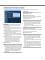
■ [MPEG-4 setup (CH individual)]
[Transmission type]
Select a MPEG-4 transmission type from the following.
Unicast port (AUTO): Up to 8 users can access a single camera concurrently. "Unicast port1 (Image)"
27
and "Unicast port2 (Audio)" will automatically be
selected when transmitting images and audio from
the unit.
When it is unnecessary to fix the port number for
MPEG-4 image transmission such as when using in
a particular LAN environment, it is recommended to
select "Unicast port (AUTO)".
Unicast port (MANUAL): Up to 8 users can access a
single camera concurrently. It is necessary to select
"Unicast port1 (Image)" and "Unicast port2 (Audio)"
manually to transmit images and audio from the unit.
It is possible to fix the port number of the router used
for MPEG-4 image transmission via the Internet by
setting "Unicast port (MANUAL)". Refer to the operating instructions of the router in use.
Multicast: No concurrent access limitation for a unit.
Refer to page 4 for further information about the
maximum concurrent access number.
Default setting: Unicast port (AUTO)
Important:
When "Multicast" is selected, set the value of "Total
bit rate" greater than the total value of "Max bit rate
(per 1 client)" of all the channels.
[Max number of MPEG-4 clients]
Select the number of users to transmit MPEG-4 images
at a time. Up to 8 users are available.
* MPEG-4 images are not transmitted from each
channel to more users than the maximum number.
Available value: 1 - 8
Default setting: 4
Important:
• Depending on the PC in use for monitoring, the multicast port number may be already in use. In this
case, it may be impossible to monitor images.
Change the multicast port number.
• When transmitting MPEG-4 image via a network, the
transmitted image sometimes may not be displayed.
In this case, refer to the network administrator.
• When two or more network interface cards are
installed on the PC in use, the network interface
card(s) not used for receiving images should be
invalidated when displaying images using the multicast port.
[Unicast port1 (Image)]
Enter the unicast port number (used to transmit images
from the camera).
28
Available value: 1024 - 50000 (Only even numbers are
available.)
Default setting:
CH1: 32004
CH2: 32006
CH3: 32008
CH4: 32010
[Unicast port2 (Audio)]
Enter the unicast port number (used to transmit audio
from the unit).
Available value: 1024 - 50000 (Only even numbers are
available.)
Default setting: 33004
[Multicast address]
Enter the multicast IP address.
Images and audio will be transmitted to the designated
IP address.
Available value: 224.0.0.0 - 239.255.255.255
Default setting: 239.192.0.20
[Multicast port]
Enter the multicast port number (used to transmit
MPEG-4 images from the unit).
Available value: 1024 - 50000 (Only even numbers are
available.)
Default setting:
CH1: 37004
CH2: 37006
CH3: 37008
CH4: 37010
[Multicast TTL]
Enter the multicast TTL value.
Available value: 1 - 254
Default setting: 16
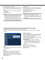
■ Calculation of refresh interval (JPEG)
It is possible to calculate an interval to refresh the displayed JPEG image that can be transmitted to the max
number of users accessing.
Calculated values are approximate. Refresh interval
changes depending on the settings or the network status.
[Number of JPEG clients when connecting with max
number of MPEG-4 clients]
The number of JPEG clients of each channel that can
connect when the number of accessing MPEG-4 clients
is maximum is displayed.
[Number of JPEG monitoring clients]
Select the number of users of each channel to monitor
JPEG images on the browser.
[Number of JPEG receiving devices]
Select the number of connected devices of each channel to receive JPEG images.
[Refresh interval of JPEG monitoring clients]
The set value for refresh interval when monitoring JPEG
images on the browser is displayed.
[Refresh interval of JPEG receiving devices]
The set value for refresh interval that can be secured
when transmitting JPEG images to each connected
device.
About the individual setup menu
It is possible to configure the settings for JPEG and MPEG-4 images of each channel individually. When configuring
the settings, consider the network load carefully.
After configuring the settings in the individual setup menu and returning to the [JPEG/MPEG-4] menu, changed
items are marked with "*".
[Return]
Returns to the [JPEG/MPEG-4] menu. (☞ page 26)
[CH No.]
Select a channel to configure the setting.
* Refer to page 26 to 28 for setting items.
Note:
When setting "Refresh interval (JPEG)", note the following.
• When "OFF" is selected for "MPEG-4 transmission" on the setup menu, the total refresh interval
of all the selected channels shall be 40 fps or
less. (When "QVGA" is selected for "Image capture size", divide the value by four.)
(Example: When the set values are
CH1: VGA,10 fps,
CH2: VGA, 15 fps,
CH3: QVGA, 30fps,
CH4: QVGA, 30fps:
10 (CH1) + 15 (CH2) + 30/4 (CH3) + 30/4 (CH4)
= 40 fps (Total))
• When "ON" is selected for "MPEG-4 transmission" in one or more channels, the total refresh
interval of all the selected channels shall be 15
fps or less. (When "QVGA" is selected for "Image
capture size", divide the value by four.)
If the set values exceed these settings, the refresh
interval of each channel may be lower.
The refresh interval may also be lower depending on
the set value of "Image quality", the image contents,
or the network status.
When the setting of each channel is changed individually, it is impossible to calculate an interval to
refresh the displayed JPEG image.
29
Configure the settings relating to camera [Camera]
Click the [Camera] tab on the "Camera setup" page. (☞ page 26)
The following are descriptions of how to display the setup menu and configure the settings relating to camera operation using the operation panel. Refer to the provided operating instructions for further information about emergency
recording.
[CH No.]
Select a channel to configure the setting relating to the
camera operation.
ZOOM buttons, FOCUS buttons, Control
pad/buttons
Refer to page 6 for further information.
About the operation panel
Use the following buttons on the operation panel to operate the "Camera setup" page using a PC.
[ON] button: Click this button to display the top
page of the "Camera setup" page.
[ESC] button: Click this button to return
to the previous page.
[OFF] button: Click this button to close the
"Camera setup" page.
[RESET/SPECIAL] button: Display the
SETUP MENU of camera, move the cursor onto
SPECIAL, and click this button to move to the SPECIAL SETUP menu.
Move the cursor onto REFRESH on the SPECIAL
SETUP menu, and click this button to refresh the
camera position.
For further information, refer to the operating instructions of the camera.
[SET] button: Click this button to move to the
submenu.
[Left] button/
[Right] button: Click
these button to select the parameters.
[Down] button/
[Up] button: Click
these buttons to move the cursor.
30
[ALL RESET] button: Click this button
after moving the cursor onto CAMERA RESET on
the SPECIAL SETUP menu to reset to the default
setting. Refer to the operating instructions of each
camera for further information about the settings to
be reset.
Configure the settings relating to audio [Audio]
Click the [Audio] tab on the "Camera setup" page. (☞ page 26)
The following are descriptions for when the settings relating to audio from CH1 is configured on this page.
[Audio bit rate]
Select "16 kbps" or "32 kbps" for the audio bit rate used
to transmit/receive audio data.
Default setting: 32 kbps
[Mic input interval (Unit to PC)]
Select an interval for audio reception from the following.
20 msec/40 msec/80 msec/160 msec
Default setting: 40 msec
[Audio mode]
Select the communication mode used for audio data
transmission/reception between the unit and the PC
from the following.
OFF: Does not transmit audio from the unit to the PC.
Therefore, the settings and controls relating to audio
will be invalidated.
Mic input: The PC receives audio data from the unit.
Audio can be heard with images on the PC. Images
and audio will not be synchronized.
Audio output: Audio data from the PC will be transmitted to the unit. Audio can be heard from the speaker
connected to the unit.
Interactive: The PC receives audio data from the unit.
Audio can be heard with images on the PC. Audio
transmitted from the PC to the unit can also be
heard from the speaker connected to the unit
(Transceiver type). However, audio data cannot
simultaneously be transmitted and received.
Default setting: OFF
Note:
When "Multicast" is selected for "Transmission type"
of "MPEG-4 setup" in the "MPEG-4 setup" section of
the [JPEG/MPEG-4] tab of the "Camera setup" page
(☞ page 28), it is impossible to carry out the audio
output operation while monitoring MPEG-4 image.
To carry out the audio output operation, click the
[JPEG] button.
Note:
When a shorter interval is selected, the delay time
will be shorter. When a longer interval is selected,
audio interruption may be diminished even though
the delay time will be longer.
Select the interval according to the network environment.
[Audio output interval (PC to Unit)]
Select an interval for audio transmission from the following.
160 msec/320 msec/640 msec/1280 msec
Default setting: 640 msec
Notes:
• When a shorter interval is selected, the delay time
will be shorter. When a longer interval is selected,
audio interruption may be diminished even though
the delay time will be longer.
Select the interval according to the network environment.
• Audio may temporarily be interrupted or noise may
be heard when panning, tilting or zooming the camera, or when multiple users are accessing concurrently. It may be possible to diminish the interruption
or noise by setting a longer interval for "Audio output
interval (PC to Unit)".
31
[Audio output port (PC to Unit )]
Enter the transmission port number (the port number on
the unit used to receive audio data transmitted from the
PC).
Available value: 1024 - 50000 (Only even numbers are
available.)
Default setting: 34004
Note:
The transmission port number entered for "Audio
output port (PC to Unit)" will be used only when
transmitting MPEG-4 images. When "OFF" is selected for "MPEG-4 transmission" (☞ page 27), it is not
necessary to enter the transmission port number.
[Authentication]
Select an access level for audio transmission/reception
from the following. Refer to page 46 for further information about the access level.
Level 1 only/Level 2 or higher/All users
Default setting: All users
Notes:
• Images and audio will not be synchronized.
Therefore, images and audio may not always match.
• Audio may be interrupted depending on the network
environment.
Configure the settings relating to coaxial communication [Coaxial setup]
Click the [Coaxial setup] tab on the "Camera setup" page. (☞ page 26)
The settings relating to camera control and cable compensation with coaxial communication can be configured on
this page.
[CH No.]
Select a channel to configure the setting, and configure
the following items.
[DATA]
Select "ON" or "OFF" to determine whether or not to
control cameras with the coaxial communication.
ON: Controls cameras with coaxial communication.
OFF: Not controls cameras with coaxial communication.
Default setting: ON
32
[Cable compensation]
Select the desired settings for cable compensation (the
function to compensate the attenuation of video input
signals) according to the cable length.
Perform the settings for the cable compensation properly according to the cable length.
Otherwise camera pictures may not be displayed/
recorded correctly.
* The following cable length settings are references
when using RG-59/U, BELDEN 9259 (for NTSC
models), 5C-2V (for PAL models) or equivalent
cables.
S: Less than 400 m {1 300 ft.}
M: 400 m {1 300 ft.} to 700 m {2 300 ft.}
L: 700 m {2 300 ft.} to 1 200 m {4 000 ft.}
Default setting: S
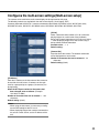
Configures the multi-screen settings [Multi-screen setup]
The cameras to be used for the multi-screen display can be registered on this page.
The following cameras are available for the multi-screen display. (As of August, 2007)
Cameras connected to WJ-NT314, cameras connected to the network, WV-NP240 series, WV-NP1000 series,
WV-NW470S series, WV-NP472, WV-NS320 series, WV-NS202, WV-NF284, WV-NS202A, WJ-NT304
[CH No.]
Select a desired channel number (CH1 to 4) when displaying images on a multi-screen using a network
device with channel information such as this unit. Select
"-" when displaying images on a multi-screen using a
device without channel information.
Available value: -, 1 - 4
Default setting: [Camera title]
Enter the title of the camera. The entered camera title
will be displayed on a multi-screen.
Number of characters that can be entered: 0 - 20
characters
Default setting: (blank)
[IP address]
Enter the IP address or the host name of the camera to
be used for the multi-screen. 4 cameras can be registered as a group and up to 4 groups (16 cameras) can
be registered.
When the HTTP port number for the camera had
been changed, enter as follows: (Example:
192.168.0.10: 8080)
Number of characters that can be entered: 1 - 128
characters
Default setting: (blank)
Notes:
• When using the host name, it is necessary to configure the DNS settings of the PC in use.
• When displaying images from cameras connected to
this unit on a multi-screen, set the IP address of the
unit.
33
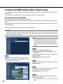
Configure the AVMD settings [Video analytics setup]
The settings relating to the detection area, depth, and schedule for AVMD can be configured on the "Video analytics
setup" page.
The "Video analytics setup" page has 2 tabs of the [AVMD] tab, and the [Schedule] tab.
Set the detection program [AVMD]
Click the [AVMD] tab on the "Video analytics setup" page.
Set the detection program for AVMD. It is possible to set up to 8 preset positions (CH1 to CH4) for 8 detection programs.
It is possible to set intruder detection area (3 types), object abandonment / removal detection area, and an area not
to activate AVMD.
When editing the detection program, perform the same procedure.
Important:
The detection program will not be applied to the AVMD function only with setting. To apply the setting, select the
detection program for "AVMD" of the [Alarm] tab on the "Alarm setup" page. (☞ page 40) However, up to 2 channels of CH1 to CH4 are available.
Note:
When the detection program has already been set,
the edited titles will be displayed on the pull-down
menu. It is possible to display and change the settings by selecting a title and clicking the [DISPLAY]
button.
Step 1
Select the title of desired detection program from
"Detection program", and click the [DISPLAY] button.
→ Setup items will be displayed.
Step 2
Enter the title in "Detection program title".
Number of characters that can be entered: 1 - 20
characters
When "Detection program title" is blank, the default setting will be applied.
Default setting: 1-8 Detection program
Step 3
Select the channel to activate the AVMD from "CH No.".
Available value: 1 - 4
Step 4
Enter the preset position number to activate the AVMD
in "Preset No.", and click the [GO] button.
Available value: (blank), 1 - 256
34
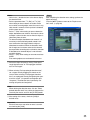
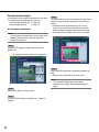
Step 5
Select the area to detect an intruder, object abandonmentt, or object removal.
q Click one of the icons from "1-(Blu)" to "Bla" of "Area
type".
Notes:
• Color in the ( ) beside the icon is the color to display
the detection area.
• Select a parameter from "P1 (Blu)" to "P3 (Yel)"
when setting an area to detect an intruder. Alarm
occurs when a moving object enters the area. It may
take around 2 seconds since the person is detected
until the alarm occurs.
• Select "P (Bro)" when setting an area to detect the
object abandonment or removal. Alarm occurs when
an object is taken into the area or when the object is
taken away from the area.
• To detect the object abandonment or removal, it is
necessary to shoot the background around 2 minutes to memorize the image before the object is
abandoned or removed. When the detection condition changes and a camera moves to the selected
preset positions according to the schedule, detection
of abandoned or removed objects is not activated
around 2 minutes.
• Select "P (Bla)" when setting an area not to activate
AVMD.
Even moving objects are not detected in the area.
Step 6
After completing the detection area settings, perform the
depth correction.
Click the [BSET] button to move to the "Depth correction" menu. (☞ page 36)
w Select the shape of frame by clicking "Paint quadrangle detection area" or "Paint polygon detection
area" of "Paint type".
e When selecting "Paint quadrangle detection area",
set a square area by dragging the mouse on the
screen. When selecting "Paint polygon detection
area", set a polygonal area by designating the apexes on the screen. (It is possible to designate up to
16 apexes.) The detection area is painted by connecting start points and end points.
Note:
When deleting the detection area, click the "Select
painted detection area" icon, select the frame on the
screen by the mouse, and click the [CLEAR] button.
r After setting all the areas, check the [Valid] of
desired areas.
Important:
Alarm will not occur even when an area is set without checking the [Valid].
35
Set the detection depth
It is possible to set the depth information for each detection program both automatically and manually.
• Set the depth automatically (☞ page 36)
• Set the depth manually
(☞ page 37)
Set the depth automatically
Note:
To set the depth automatically, have a person move
forward and backward several times within the
image being detected.
Step 4
The person moves forward and backward several times
within the image at the preset position of the selected
channel.
→ Calculation result will be displayed in 3D on the
screen. The result will be refreshed every second.
When the depth is properly calculated (or when the
3D display become stable), click the [STOP] button.
Step 1
Click the [SET] button of "Depth correction" on the
[AVMD] tab.
→ The "Depth correction" menu will be displayed.
Step 5
Click the [SAVE] button after completing the depth settings.
→ Returns to the "Detection area setup" menu.
Note:
Click the [RETURN] button to return to the
"Detection area setup" menu without setting the
depth.
Step 2
Select "Auto setup" for "Setup mode".
Step 3
Click the [START] button of "Auto setup" – "Depth calculation".
36
Set the depth manually
Step 1
Click the [SET] button of "Depth correction" on the
[AVMD] tab.
Step 4
After drawing the marker, click the [Execute] button of
"Depth calculation".
→ Calculation result is displayed in 3D on the screen.
→ The "Depth correction" menu will be displayed.
Step 2
Select "Manual setup" for "Setup mode".
Step 3
Draw a marker by dragging the mouse between the
front side and rear side on the screen.
Step 5
Click the [SAVE] button after completing the settings.
→ Returns to the "Detection area setup" menu.
Note:
Click the [RETURN] button to return to the
"Detection area setup" menu without setting the
depth.
Notes:
• By dragging the mouse up and down, the size of
marker will become larger or smaller. (Horizontal to
vertical ratio is fixed to 1:3.)
• To retry drawing the marker, click [CLEAR] button.
• Assuming that people go forward and backward, it is
possible to calculate the correct depth by drawing
the larger marker for the nearer object (lower area in
the image) and the smaller marker for the farther
object (upper area in the image).
37
Set the AVMD schedule [Schedule]
Click the [Schedule] tab on the "Video analytics setup" page.(☞ page 34)
It is possible to set the schedule for each detection program.
For example, to monitor the entrance and exit, it is possible to set the detection program for the entrance between 6
a.m. and 12 a.m. on Monday to Friday, and for the exit between 4 p.m. and 12 p.m. on Monday to Friday.
How to configure the schedule settings
Step 6
To check the schedule on the time bar, click [i] and
select the channel number (detection program) from the
[CH No.] pull-down menu.
→ The schedule of detection program set for the selected channel will be displayed on the time bar. The colors of time bar differ depending on detection programs. (The colors are displayed beside [CH No.])
Step 1
Select the schedule number from "Schedule 1" to
"Schedule 8".
Step 2
Check the check box of the desired day of the week.
→ The selected day of the week will be validated for the
schedule.
Step 3
To designate time, click [i] and select the desired
"hour" and "minute".
When not designating time, check the checkbox of "24
hours".
Available value: 00:00 – 23:59
Step 4
Select the detection program.
→ The channel number set for the selected detection
program will be displayed in "CH No.".
Step 5
Click the [SET] button after completing the settings.
38
How to delete the set schedule
Step 1
Select the schedule number from "Schedule 1" to
"Schedule 8".
Step 2
Uncheck the check box of the set day of the week.
Step 3
Click the [SET] button after completing the settings.
Step 4
To check the schedule on the time bar, click [i] and
select the channel number (detection program) from the
[CH No.] pull-down menu.
39
Configure the alarm settings [Alarm setup]
The settings relating to alarm occurrences such as settings for the alarm action at an alarm occurrence and the
alarm occurrence notification can be configured on the "Alarm setup" page.
The "Alarm setup" page has 2 tabs of the [Alarm] tab, and the [Notification] tab.
Configure the settings relating to the alarm action [Alarm]
Click the [Alarm] tab on the "Alarm setup" page.
The settings relating to the alarm action can be configured on this page. Refer to pages 42 and 43 for further information about the settings relating to the alarm image and the alarm out connector.
■ Alarm setup
[AVMD (CH1)] to [AVMD (CH4)]
The AVMD (detection program) setting is applied. Up to
2 channels are available.
When the AVMD (detection program) setting is applied
to 2 channels, the settings of other channels will be displayed in gray.
The following values are available.
OFF: AVMD will become unavailable.
Detection program (up to 8): AVMD will be applied to
the selected detection program.
Schedule: Detection program will be changed and the
AVMD will be activated according to the schedule
set on the [Schedule] tab.
Default setting: OFF
Event CH
Select the channel (CH1 to 4) to activate preset positions and auto track when the AVMD is detected.
Note:
This setting is unavailable for the channel for which
AVMD is activated.
Preset No.
When selecting a preset position number, the camera
connected to the video input connector of event CH
(CH1 to 4) will move to the selected preset position
when the AVMD is detected.
Available value: (blank), 1 - 256
Default setting: (blank)
40
Auto mode
It is possible to activate auto mode for the camera connected to the video input connector of event CH (CH1 to
4) when the AVMD is detected. (When a preset position
number is selected, operation starts after the camera
moves to the preset position.)
Auto track: Performs auto track when the camera supports auto track (AUTO TRACK).
–: OFF
Default setting: –
The command alarm is the function that receives
Panasonic alarm protocol from other Panasonic’s network devices. Using this function, alarm actions will be
performed between multiple network devices. When
"ON" is selected, alarm image FTP transmission and
alarm output are activated for the selected channel.
(When "-" is selected, alarm image FTP transmission
and alarm output are unavailable.)
Available value: –, CH1 to 4
Default setting: CH1
[Terminal alarm 1 to 4]
Select "ON" or "OFF" to determine whether or not to
receive Terminal alarm 1 to 4 (input to the connector
terminal (Alarm Input No. 1 to 4)).
ON: Receives alarms.
OFF: Does not receive.
Default setting: OFF
When "ON" is selected, the camera connected to the
video input connector of CH1 will move to the selected
preset position when Terminal alarm 1 is detected.
Available value: (blank), 1 - 256
Defalut setting: (blank)
When "ON" is selected, the camera connected to the
video input connector of CH1 to 4 will move to the
selected preset position when Terminal alarm 1 to 4 is
detected.
Available value: (blank), 1 - 256
Defalut setting: (blank)
[Originating port number]
Select a port number to be used to receive the command alarm.
Available value: 1 - 65535
Default setting: 8181
[Camera site alarm (CH1 to 4)]
Select "ON" or "OFF" to determine whether or not to
receive the camera site alarm from the camera connected to the video input connector of CH1 to 4.
ON: Receives alarms.
OFF: Does not receive.
Default setting: OFF
[Video loss (CH1 to 4)]
Select "ON" or "OFF" to determine whether or not to
detect the video loss from the camera connected to the
video input connector of CH1 to 4.
ON: Detects video loss.
OFF: Does not detect.
[Command alarm]
Select "ON" or "OFF" to determine whether or not to
receive the command alarm. When "ON" is selected,
perform the following settings.
ON: Receives alarms.
OFF: Does not receive.
Default setting: OFF
41
Configure the settings relating to the alarm image [Alarm image setup]
Click the [Alarm] tab on the "Alarm setup" page. (☞ page 40)
The settings relating to the alarm image to be transmitted to the FTP server can be configured on this page. The
alarm image will be transmitted to the FTP server. To transmit alarm images to the FTP server, it is necessary to
configure the settings in advance. (☞ page 49)
Refer to pages 40 and 43 for further information about the settings relating to the alarm action and the alarm out
connector.
Important:
• Depending on the network line speed or the network traffic, images may not be transmitted at the exact designated interval or period.
• Image capture size and image quality of "JPEG setup" on the [JPEG/MPEG-4] tab are applied for the alarm
image to be transmitted. (☞ page 27)
[File name]
Enter the file name used for the alarm image to be
transmitted to the FTP server. The file name will be as
follows.
File name: ["Entered file name" + "Time and date
(year/month/day/hour/minute/second)"] + "Serial
number"
Number of characters that can be entered: 1 - 8 characters
Default setting: (blank)
■ Alarm image setup
[To FTP setup]
When "To FTP setup" is clicked, the [FTP] tab of the
"Server setup" page will be displayed. (☞ page 49)
[Alarm image FTP transmission]
Select "ON" or "OFF" to determine whether or not to
transmit the alarm image to the FTP server.
Default setting: OFF
[Directory]
Enter the directory name where the alarm images are to
be saved.
For example, enter "/ALARM" to designate the directory
"ALARM" under the FTP root directory.
Number of characters that can be entered: 0 - 256
characters
Default setting: (blank)
42
[Post alarm]
[Transmission interval]
Select a transmission interval for the alarm image FTP
transmission from the following.
0.1 fps/0.2 fps/0.33 fps/0.5 fps/1 fps
Default setting: 1 fps
[Number of images]
Select the number of images to be transmitted from the
following.
1 pic/2 pics/3 pics/4 pics/5 pics/6 pics/7 pics/8 pics/9
pics/10 pics/20 pics/ 30 pics/50 pics/100 pics/200 pics/
300 pics/500 pics/1000 pics/2000 pics/3000 pics/
5000 pics
Default setting: 100 pics
[Recording duration]
Approximate time to be taken to save the set "number of
images" with the set "transmission interval" will be displayed.
Configure the settings relating to the alarm out connector [Alarm output setup]
Click the [Alarm] tab on the "Alarm setup" page. (☞ page 40)
The settings relating to the alarm output terminals (Alarm Output No. 1 to 4) can be configured on this page. Alarm
Output No. 1 to 4 is associated with each alarm input of CH1 to 4. Refer to pages 40 and 42 for further information
about the settings relating to the alarm action and the alarm image.
Note:
When "OPEN" is selected, the alarm signal will be
output for around 90 seconds when the power of the
unit is turned on.
[Pulse width]
When "Pulse" is selected for "Alarm output", select an
alarm output terminal duration from the following.
Available value: 1 - 120 sec
Default setting: 1 sec
■ Alarm output terminal setup
■ AUX name
Select a desired alarm output terminal number from the
pull-down menu, and configure the following items.
The names of "AUX", "OPEN" and "CLOSE" on the
"Live" page can be changed.
[Alarm output setup]
Select "ON" or "OFF" to determine whether or not to
output the alarm signals to the alarm out connector
when an alarm is detected.
Default setting: OFF
[AUX (Up to 10 characters)]
Enter the name for "AUX" on the "Live" page.
Number of characters that can be entered: 1 - 10
characters
Default setting: AUX
[External terminal output setup]
Select "Latch" or "Pulse" for the alarm output terminal at
an alarm occurrence.
Latch: When an alarm is detected, alarm output connector will be in the state selected for "Alarm output"
until the alarm occurrence indication button is
clicked.
Pulse: When an alarm is detected, the alarm output terminal will be in the state to the "Alarm output" setting
for the period set for "Pulse width".
Default setting: Latch
[OPEN (Up to 5 characters)]
Enter the name for "OPEN" of "AUX" on the "Live" page.
Number of characters that can be entered: 1 - 5 characters
Default setting: OPEN
[CLOSE (Up to 5 characters)]
Enter the name for "CLOSE" of "AUX" on the "Live"
page.
Number of characters that can be entered: 1 - 5 characters
Default setting: CLOSE
[Alarm output]
Select "OPEN" or "CLOSE" to determine whether to
open or close the alarm output connector when output
the alarm signals.
OPEN: The alarm out connector will open when output
the alarm signals. (Normally close)
CLOSE: The alarm out connector will close when output
the alarm signals. (Normally open)
Default setting: CLOSE
43
Configure the settings relating to the mail notification [Notification]
Click the [Notification] tab on the "Alarm setup" page. (☞ page 40)
The settings relating to the alarm mail can be configured on this page. To notify of an alarm occurrence by e-mail, it
is necessary to configure the settings of the mail server. (☞ page 48)
[Mail body]
Enter the mail body.
Number of characters that can be entered: 0 - 200
characters
Default setting: (blank)
■ E-mail notification setup
[To E-mail server setup]
When "To E-mail server setup" is clicked, the [Mail] tab
of the "Server setup" page will be displayed. (☞ page
48)
[E-mail notification]
Select "ON" or "OFF" to determine whether or not to
notify of an alarm occurrence by e-mail at an alarm
occurrence.
Default setting: OFF
■ E-mail notification setup
[Address 1] to [Address 4]
Enter the destination mail address. Up to 4 destination
addresses can be registered.
To notify by e-mail when an alarm occurred, check the
"Alarm" checkbox respective to the desired address.
To delete the registered address, click the [DEL] button
respective to the desired address.
Number of characters that can be entered: 3 - 128
characters
Default setting: (blank)
[Mail subject]
Enter the mail subject.
Number of characters that can be entered: 0 - 50
characters
Default setting: (blank)
44
Notes:
• By entering "%p%", it is possible to transmit alarm
type and channel information.
• By entering %y%”, “%m%”, “%d%”, or “%t%”, it is
possible to transmit the year, month, date or time
information only.
%y%: Year when the alarm occurs
%m%: Month when the alarm occurs
%d%: Date when the alarm occurs
%t%: Time when the alarm occurs
When the mail body is blank, year, month, date and
time information will be transmitted.
Configure the settings relating to Panasonic alarm protocol [Panasonic alarm
protocol]
Click the [Notification] tab on the "Alarm setup" page. (☞ page 40)
The settings relating to Panasonic alarm protocol can be configured on this page.
■ Panasonic alarm protocol
[IP address 1] to [IP address 8]
Enter the destination IP address of the Panasonic alarm
protocol from the following. Host name is unavailable for
the IP address. Up to 8 destination addresses can be
registered.
Default setting: (blank)
■ Panasonic alarm protocol setup
[Panasonic alarm protocol]
Select "ON" or "OFF" to determine whether or not to
notify of an alarm occurrence by Panasonic alarm protocol when an alarm is detected.
Default setting: OFF
Note:
When "ON" is selected, the alarm occurrence will be
notified to the registered destination IP addresses in
order (to IP address 1 first, to IP address 8 last).
[Destination port]
Select a destination port of the Panasonic alarm protocol from the following.
Available value: 1 - 65535
Default setting: 1818
[Retry times]
Select a retry time of Panasonic alarm protocol.
Available value: 1 to 30
Default setting: 2
<Unavailable IP addresses>
0.*.*.*
*.*.*.0
255.*.*.*
*.*.*.255
127.0.0.1
Class D address (224.0.0.0 - 239.255.255.255)
Class E address (240.0.0.0 - 255.255.255.255)
To provide notification at an alarm occurrence to the
desired IP address using Panasonic alarm protocol,
check the "Alarm" checkbox respective to the desired IP
address.
To provide notification using Panasonic alarm protocol
when any of the following has occurred, check the
"Diag." checkbox respective to the desired address.
• When notification of the remaining space of the SD
memory card has been provided (☞ page 23)
• When the SD memory card has become full
• When mounting of the SD memory card has failed
To delete the registered address, click the [DEL] button
respective to the desired address.
Important:
• Confirm that the destination IP addresses are registered correctly. When a registered IP address does
not exist, notification may be delayed.
• Depending on the status of this unit or network, notification may be delayed. When activating event
recording, it is recommended to set pre-event
recording to be performed.
45
Configure the settings relating to the authentication
[Authentication setup]
The settings relating to the authentication such as users and PCs restrictions for accessing the unit can be configured on this page.
The "Authentication setup" page has 2 tabs of the [User] tab and the [Host] tab.
Configure the settings relating to the user authentication [User]
Click the [User] tab on the "Authentication setup" page.
The settings relating to the user authentication can be configured on this page. Up to 16 users can be registered.
Note:
When user authentication (authentication error) has failed to pass 8 times (6 times when clicking the [Go] button
of the browser) within 30 seconds using the same IP address (PC), access to the camera will be denied for a
while.
Note:
When the user name already in use is entered and
the [SET] button is clicked, the respective user information will be overwritten.
For example, the password for the administrator can
be changed by entering "admin" for "User name",
selecting "1. Administrator" for "Access level", entering a desired password, and clicking the [SET] button.
[User authentication]
Select ON or OFF to determine whether or not to
authenticate the user.
Default setting: OFF
[User name]
Enter a user name.
Number of characters that can be entered: 1 - 32
characters
Default setting: (blank)
[Password] [Retype password]
Enter the password.
Number of characters that can be entered: 4 - 32
characters
Default setting: (blank)
46
[Access level]
Select the access level of the host from the following.
1. Administrator: Allowed all available operations of
the unit.
2. Camera control: Allowed to display images from the
unit and to control the unit. The unit setting configuration is unavailable.
3. Live only: Only displaying live images is available.
The unit setting configuration and unit control are
unavailable.
Default setting: 3. Live only
Note:
By clicking [i] of "User name check", the registered
user can be selected and the selected user’s information can be checked.
The registered user will be displayed with the access
level. (Example: admin [1])
To delete the registered user, click the [DEL] button
after selecting the user to be deleted.
Configure the settings relating to the host authentication [Host]
Click the [Host] tab on the "Authentication setup" page. (☞ page 46)
The settings to restrict PCs (IP address) to access the unit can be configured on this page.
[Access level]
Select the access level of the host from the following.
1. Administrator/2. Camera control/3. Live only
Refer to page 46 for further information about the
access level.
Default setting: 3. Live only
[Host authentication]
Select "ON" or "OFF" to determine whether or not to
authenticate the host.
Default setting: OFF
Note:
By clicking [i] of "Host check", the registered host
can be selected and the selected host’s IP address
can be checked.
The registered IP address will be displayed with the
access level. (Example: 192.168.0.21 [1])
To delete the registered host, click the [DEL] button
after selecting the IP address to be deleted.
Important:
Before selecting "ON" for "Host authentication", it is
necessary to register IP addresses of the PCs to be
allowed to access the unit and determine their
access levels.
[IP address]
Enter the IP address of the PC to be allowed to access
the unit.
Host name is unavailable for the IP address.
Default setting: (blank)
Notes:
• When "IP address/subnet mask" is entered, it is possible to restrict PCs in each subnet.
For example, when "192.168.0.1/1/24" is entered
and "2. Camera control" is selected for the access
level, the PCs whose IP address is between
"192.168.0.0" - "192.168.0.255" can access the
camera with the access level "2. Camera control".
• When the IP address already in use is entered and
the [SET] button is clicked, the respective host information will be overwritten.
47
Configure the settings of the servers [Server setup]
The settings relating to the mail server and the FTP server can be configured on this page.
The "Server setup" page has 2 tabs of the [Mail] tab and the [FTP] tab.
Configure the settings relating to the mail server [Mail]
Click the [Mail] tab on the "Server setup" page.
The settings relating to the mail server used to send the alarm mail can be configured on this page.
[Authentication]
Select the authentication method to send e-mails from
the following.
None: It is not necessary to clear any authentication to
send e-mails.
POP before SMTP: It is necessary to clear the POP
server authentication first to use the SMTP server to
send e-mails.
SMTP: It is necessary to clear the SMTP server authentication to send e-mails.
Default setting: None
[SMTP server address]*
Enter the IP address or the host name of the SMTP
server used to send e-mails.
Number of characters that can be entered: 1 - 128
characters
Default setting: (blank)
[POP server address]*
When "POP before SMTP" is selected for
"Authentication", enter the IP address or the host name
of the POP server.
Number of characters that can be entered: 1 - 128
characters
Default setting: (blank)
Important:
When entering the host name for "NTP server
address", it is necessary to configure the DNS settings on the [Network] tab of the "Network setup"
page. (☞ page 51)
48
Note:
When you don’t know the authentication method to
send e-mails, refer to the network administrator.
[User name]
Enter the user name to access the server.
Number of characters that can be entered: 1 - 32
characters
Default setting: (blank)
[Password]
Enter the password to access the server.
Number of characters that can be entered: 0 - 32
characters
Default setting: (blank)
[Sender mail address]
Enter the mail address of a sender.
Entered mail address will be displayed in the "From"
(sender) line of the sent mails.
Number of characters that can be entered: 3 - 128
characters
Default setting: Blank
Configure the settings relating to the FTP server [FTP]
Click the [FTP] tab on the "Server setup" page. (☞ page 48)
The settings relating to the FTP server used to transmit the alarm images can be configured on this page.
[FTP mode]
Select "Passive" or "Active" for the FTP mode.
Normally, select "Passive". When failed to establish the
connection, select "Active".
Default setting: Passive
[FTP server address]
Enter the IP address or the host name of the FTP server.
Number of characters that can be entered: 1 - 128
characters
Default setting: (blank)
Important:
When entering the host name for "FTP server
address", it is necessary to configure the DNS settings on the [Network] tab of the "Network setup"
page. (☞ page 51)
[User name]
Enter the user name (login name) to access the FTP
server.
Number of characters that can be entered: 1 - 32
characters
Default setting: (blank)
[Password]
Enter the password to access the FTP server.
Number of characters that can be entered: 0 - 32
characters
Default setting: (blank)
[Control port]
Enter a control port number to be used for the FTP server.
Available port number: 1 - 65535
Default setting: 21
49
Configuring the network settings [Network setup]
The network settings and the settings relating to DDNS (Dynamic DNS) and SNMP (Simple Network management
Protocol) can be configured on this page.
The "Network setup" page has 4 tabs of the [Network] tab, the [DDNS] tab, the [SNMP] tab and the [FTP] tab.
Configure the network settings [Network]
Click the [Network] tab on the "Network setup" page.
The following information is required to configure the network settings.
Contact the network administrator or your Internet service provider.
• IP address
• Net mask
• Default gateway (when using the gateway server/router)
• HTTP port Number
• Primary DNS, Secondary DNS (when using DNS)
<Unavailable IP addresses>
0.*.*.*
*.*.*.0
255.*.*.*
*.*.*.255
127.0.0.1
Class D address (224.0.0.0 - 239.255.255.255)
Class E address (240.0.0.0 - 255.255.255.255)
* These IP addresses are unavailable even when
using the DHCP function. Refer to the network
administrator for the settings of the DHCP server.
■ Network setup
[DHCP]
Select "ON" or "OFF" to determine whether or not to use
the DHCP function.
Configure the DHCP server not to assign the same IP
addresses used for the other network cameras and PCs
whose IP address is unique. Refer to the network
administrator for the settings of the server.
Default setting: OFF
[IP address]
When not using the DHCP function, enter the IP
address of the unit. Do not enter the IP address already
in use (for the PCs and the other network cameras).
Default setting: 192.168.0.10
50
[Net mask]
When not using the DHCP function, enter the net mask
of the unit.
Default setting: 255.255.255.0
[Default gateway]
When not using the DHCP function, enter the default
gateway of the unit.
Default setting: 192.168.0.1
<Unavailable IP addresses for the default gateway>
0.*.*.*
*.*.*.0
255.*.*.*
*.*.*.255
127.0.0.1
Class D address (224.0.0.0 - 239.255.255.255)
Class E address (240.0.0.0 - 255.255.255.255)
* These IP addresses for the default gateway are
unavailable even when using the DHCP function.
Refer to the network administrator for the settings of
the DHCP server.
[Line speed]
Select the line speed for data transmission from the followings. It is recommended to use the default setting
"AUTO".
AUTO: Line speed will be applied automatically.
100M-FULL: 100 Mbps full-duplex
100M-HALF: 100 Mbps half-duplex
10M-FULL: 10 Mbps full-duplex
10M-HALF: 10 Mbps half-duplex
Default setting: AUTO
[FTP access]
Select "Allow" or "Forbid" to determine whether to allow
or forbid the FTP access.
Default setting: Forbid
[HTTP port]
Assign the port numbers independently.
Available port number: 1 - 65535
Default setting: 80
[DNS]
Select "AUTO" or "MANUAL" to determine whether or
not to use the DNS.
When "MANUAL" is selected, it is necessary to configure the settings for the DNS.
When using the DHCP function, it is possible to obtain
the DNS address automatically by selecting "AUTO".
Refer to the network administrator for further information
about the settings.
Default setting: MANUAL
[Primary DNS], [Secondary DNS]
When "MANUAL" is selected for "DNS", enter the IP
address of the DNS. Refer to the network administrator
about the IP address of the DNS.
Default setting: (blank)
51
Notes:
• To access the unit via the Internet by connecting the unit to a broadband router, it is necessary to assign a
respective port number for each device and address translation by using the port forwarding function. For further
information, refer to the operating instructions of the broadband router in use.
• The port forwarding function changes a global IP address to a private IP address, and "Static IP masquerade"
and "Network Address Translation (NAT)" have this function. This function is to be set in a router.
Enter [Global IP address +:
(colon) + port number] in the
"Address" box of the browser
via the Internet.
vvv.xxx.yyy.zzz:82
vvv.xxx.yyy.zzz:81
Global address
for the WAN
vvv.xxx.yyy.zzz
Broadband router
Private address for the LAN
192.168.0.254
Address translation using the port
forwarding function
vvv.xxx.yyy.zzz:82 → 192.168.0.2:82
Internet
(WAN)
Cable modem
xDSL modem
Private address
192.168.0.2
Port number: 82
Address translation using the port
forwarding function
vvv.xxx.yyy.zzz:81 → 192.168.0.1:81
Private address
192.168.0.1
Port number: 81
52
Configure the settings relating to DDNS [DDNS]
Click the [DDNS] tab on the "Network setup" page. (☞ page 50)
The settings relating to DDNS can be configured on this page.
When accessing the unit via the Internet from the network environment of which the global IP address is obtained
using DHCP, the DDNS function is necessary.
When using the DDNS function, it is possible to access with "Host name registered in the DDNS server. nmdns.
net". To use the DDNS function, it is necessary to connect to the dedicated DDNS server. Refer to the web site for
further information about the DDNS. Refer to the "Readme" file about the web site.
It is necessary to configure the host name, user name and password registered in the DDNS server.
[Access interval]
Select the interval to access the DDNS server to check
the IP address and the host name from the following.
1 min/10 min/30 min/1 hour/6 hours/24 hours
Default setting: 1 hour
Note:
When “1 min” is selected, error message may be
displayed on the [System log] tab of the
"Maintenance" page (☞ page 57) depending on the
response from the DDNS server. This does not
affect operation of the unit.
[DDNS]
Select "ON" or "OFF" to determine whether or not to use
the DDNS function.
Default setting: OFF
[Host name]
Enter the host name to be used.
Number of characters that can be entered: 1 - 64
characters
Default setting: (blank)
[User name]
Enter the user name (login name) to access the DDNS
server.
Number of characters that can be entered: 1 - 32
characters
Default setting: (blank)
[Password]
Enter the password to access the DDNS server.
Number of characters that can be entered: 0 - 32
characters
Default setting: (blank)
53
Configure the settings relating to SNMP [SNMP]
Click the [SNMP] tab on the "Network setup" page. (☞ page 50)
The settings relating to SNMP can be configured on this page. It is possible to check the status of the unit by connecting to the SNMP manager. When using the SNMP function, contact the network administrator.
[Contact (Destination address or phone number of
manager)]
Enter the mail address or the phone number of the
SNMP manager.
Number of characters that can be entered: 0 - 255
characters
Default setting: (blank)
Notes:
• "" is regarded as a blank.
• It may take around 30 seconds until the setting is
applied.
[Community name]
Enter the community name to be monitored.
Number of characters that can be entered: 0 - 32
characters
Default setting: (blank)
Important:
When using the SNMP function, it is necessary to
enter the community name. When no community
name is entered, the SNMP function will not work.
[Unit title]
Enter a unit title to be used to manage the unit with the
SNMP function.
Number of characters that can be entered: 0 - 32
characters
Default setting: (blank)
[Unit location]
Enter the name of the location where the unit is
installed.
Number of characters that can be entered: 0 - 32
characters
Default setting: (blank)
54
Configure the settings relating to the FTP periodic transmission [FTP periodic
transmission]
Click the [FTP] tab on the "Network setup" page. (☞ page 50)
The settings relating to the periodic transmission of images to an FTP server can be configured on this page. To
transmit images to an FTP server periodically, it is necessary to configure the settings of the FTP server in advance.
(☞ page 49) Refer to page 56 for descriptions of how to configure schedules of image transmission.
Important:
• Depending on the network line speed or the network traffic, images may not be transmitted at the exact designated interval or period.
• When "ON" is selected for both of the alarm image FTP transmission function and the FTP periodic transmission
function, the alarm image FTP transmission function will be given priority over the FTP periodic transmission
function. For this reason, images may not be transmitted at the exact designated interval or period if alarms
occur frequently.
• Image capture size and image quality of "JPEG setup" on the [JPEG/MPEG-4] tab are applied for the alarm
image to be transmitted. (☞ page 27)
[Directory]
Enter the directory name where the images are to be
saved.
For example, enter "/img" to designate the directory
"img" under the FTP root directory.
Number of characters that can be entered: 0 - 256
characters
Default setting: (blank)
■ FTP periodic transmission
[To FTP setup]
When "To FTP setup" is clicked, the [FTP] tab of the
"Server setup" page will be displayed. (☞ page 49)
[FTP periodic transmission]
Select "ON" or "OFF" to determine whether or not to
transmit images using the FTP periodic transmission
function.
When "ON" is selected, it is necessary to configure the
settings of the FTP server. (☞ page 49)
The images from the selected channel will be transmitted to the FTP server. (☞ page 26)
Default setting: OFF
[File name]
Enter the file name (name of the image file to be transmitted) and select the naming option from the following.
With time and date: File name will be ["Entered file
name" + "CH number" + "Time and date (year/
month/day/hour/minute/second)" + "Sequence number (normally "00")"].
Without time and date: File name will be the characters entered for "File name" only. When "Without
time and date" is selected, the file will be overwritten
each time a file is transmitted newly.
Number of characters that can be entered: 1 - 8 characters
Default setting: (blank)
[Interval]
Select the interval for the FTP periodic transmission
from the following.
1 sec/2 sec/3 sec/4 sec/5 sec/6 sec/10 sec/15 sec/
20 sec/30 sec/1 min/2 min/3 min/4 min/5 min/6 min/
10 min/15 min/20 min/30 min/1 hour/1.5 hours/2 hours/
3 hours/4 hours/6 hours/12 hours/24 hours
Default setting: 5 sec
55
Configure the schedule settings of the FTP periodic transmission [Schedule setup]
Click the [FTP] tab on the "Network setup" page. (☞ page 50)
The schedule settings of the FTP periodic transmission can be configured on this page. Refer to page 55 for further
information about the settings relating to the FTP periodic transmission.
How to configure the schedule settings
How to delete the set schedule
Step 1
Check the check box of the desired day of the week.
→ The selected day of the week will be validated for the
schedule.
Step 1
Uncheck the check box of the desired day of the week.
Step 2
To designate time, click [i] beside the hour and minute
and select the desired "hour" and "minute".
When not designating time, check the checkbox of "24
hours".
Step 3
Click the [SET] button after completing the settings.
→ The result will be displayed at the bottom of the window.
56
Step 2
Click the [SET] button after completing the settings.
→ The result will be displayed at the bottom of the window.
Maintenance of the unit [Maintenance]
System log check, firmware upgrade, and initialization of the setup menu can be performed on this page.
The "Maintenance" page has 3 tabs of the [System log] tab, the [Upgrade] tab and the [Initialization] tab.
Check the system log [System log]
Click the [System log] tab of the "Maintenance" page.
Up to 320 KB (approx. 4 000 logs) system logs can be saved on the SD memory card when the SD memory card is
inserted after selecting "Use" for "SD memory card" on the [SD memory card] tab (☞ page 23).
When "Not use" is selected for "SD memory card", up to 8 KB (approx. 100 logs) system logs can be saved on the
built-in memory of the unit.
When the saved system logs have reached the capacity, the newer logs will overwrite the older system logs.
The system logs will be displayed in 100 logs each.
When using the SD memory card, the logs will be saved even when the power of this unit is turned off. When not
using the SD memory card, the logs will be deleted when the power of this unit is turned off.
80 KB of system log is periodically overwritten every 5 minutes.
Considering the system log occurs periodically, it is recommended to maintain the SD memory card approx. 5 MB or
more.
• When using the SD memory card, saving the system logs will be stopped when the SD memory card becomes
full.
In this case, format the SD memory card. (☞ page 24) Or make the remaining space on the SD memory card,
select "Not use" for "SD memory card" on the [SD memory card] tab (☞ page 23), and select "Use" again.
(To notify that the SD memory card becomes full, perform the Panasonic alarm protocol setup. (☞ page 45)
[Time & date]
Time and date at the error occurrence will be displayed.
[Error message]
The descriptions about the error will be displayed.
Refer to page 60 for further information about the system logs.
57
Upgrade the firmware [Upgrade]
Click the [Upgrade] tab of the "Maintenance" page. (☞ page 57)
The current firmware can be checked and upgraded to the latest version on this page. Contact the dealer for further
information about the firmware upgrade.
Step 4
Click the [Upgrade] button.
→ The confirmation window will be displayed. When
"Do not default settings after completing the
upgrade." is selected, the confirmation window will
not be displayed.
After completing the upgrade, delete temporary
internet files. (☞ page 70)
[Model No.], [MAC address], [Serial number],
[Firmware version], [IPL version]
Information of each item will be displayed.
How to upgrade the firmware
Step 1
Contact the dealer and download the latest firmware
onto a PC.
Important:
A blank (space) cannot be used for the name of the
directory where the downloaded firmware to be
saved.
Step 2
Click the [Browse…] button and designate the downloaded firmware.
Step 3
Click the radio button respective to the desired option to
determine whether or not to initialize the settings after
the firmware upgrade.
Note:
Read the "readme" file provided with the firmware
first and determine whether or not to initialize the
settings after the firmware upgrade.
58
Important:
• Upgrade the firmware using a PC in the same subnet as of the unit’s.
• Follow the instructions from the dealer when upgrading the firmware.
• Use the designated "nt314_xxxxx.img" file for the
firmware upgrade. ("xxxxx" indicates the version of
the firmware.)
• Do not turn the power of the unit off in the process of
upgrade.
• Do not operate the web browser (including adjusting
the window size) in the process of upgrade.
• The following network settings will not be initialized
when upgrade the firmware after selecting "Reset to
default setting after completing the upgrade. (Except
network settings)".
ON/OFF for DHCP, IP address, net mask, default
gateway, HTTP port, AUTO/MANUAL for DNS, DNS
primary and secondary addresses, line speed, time
& date
Initialize/restart the unit [Initialization]
Click the [Initialization] tab of the "Maintenance" page. (☞ page 57)
Initialization of the setup data and HTML files of the unit and restarting of the unit can be performed on this page.
[Unit restart]
Click the [Execute] button to restart the unit. The unit
will be inoperable for around 3 minutes after the restart
just as when the power is turned on.
[Initialize setup data (Except network setup data)]
Click the [Execute] button to reset the settings to the
default. Note that the network settings will not be reset.
It is impossible to operate the unit for around 3 minute
after the initialization.
[Initialize HTML data]
Click the [Execute] button to reset the HTML files to the
default. It is impossible to operate the unit for around 3
minute after the initialization.
Notes:
• To initialize all the settings, do the following. Turn off
the power of the unit. Turn on the power of the unit
by setting the Dip Switch 1 on the front of this unit to
ON, and wait around 90 seconds. The unit will start
up and all the settings including the network settings
(☞ page 50) will be initialized.
When initializing the network settings (except the
HTTP port number setting) only, set the Dip Switch 2
to ON. After initialization, be sure to set the Dip
Switch 2 to OFF, and turn on the power of the unit
again. (Refer to the provided operating instructions
for further information about the dip switch.)
• When the notification function is on, notification will
be provided to the registered addresses (mail
address or IP address) when the SD memory card
has failed to mount after the restart or when the
inserted SD memory card is locked. (☞ page 45)
[Initialize setup data and HTML data]
Click the [Execute] button to reset the settings of the
unit and the HTML files to the default. Note that the network settings will not be reset. It is impossible to operate the unit for around 3 minute after the initialization.
[Video analytics setup data]
Click the [Execute] button to reset the video analytics
setup data to the default.
[Camera restart]
Click the [Execute] button to restart all the cameras connected to the unit.
After restart, it is impossible to control the cameras for
around 1 minute.
59
About the Displayed System Log
Error indications relating to SMTP
Category
POP3 server error
Content
Authentication error
Failed to find POP3 server
SMTP server error
Connection error
Internal error
SMTP authentication error
Description
Entered user name or password may be incorrect. Check if
the mail settings are configured correctly.
• The IP address of the server may be incorrect. Check if
the IP address of the server is configured correctly.
• The POP3 server may be down. Ask the network administrator.
Entered user name or password may be incorrect. Check if
the mail settings are configured correctly.
Failed to resolve mail server
address from DNS
• The designated IP address of the DNS server may be
incorrect. Check if the DNS settings are configured correctly.
• The DNS server may be down. Ask the network administrator.
Failed to find SMTP server.
• The IP address of the server may be incorrect. Check if
the IP address of the server is configured correctly.
• The SMTP server may be down. Ask the network administrator.
MAIL FROM command error
• Sender mail address may be incorrect. Check if the mail
settings are configured correctly.
RECP TO command error
• Sender mail address may be incorrect. Check if the mail
settings are configured correctly.
Other error
An error occurred in the mail function. Check if the mail settings are configured correctly.
Error indications relating to FTP
Category
FTP server error
Content
Failed to resolve FTP server address from
DNS
Failed to find FTP server.
Connection error
File transfer error
Passive mode error
Log out failed
Directory change failed
User name and password isn't correct.
60
Description
• The designated IP address of the DNS
server may be incorrect. Check if the
DNS settings are configured correctly.
• The DNS server may be down. Ask the
network administrator.
• The FTP server or DNS server may be
down. Ask the network administrator.
• The IP address of the server may be
incorrect. Check if the IP address of the
server is configured correctly.
• The FTP server settings may be incorrect. Check if the FTP settings are configured correctly.
• The settings relating to the indicated item
may be incorrect. Check if the FTP settings are configured correctly.
Category
Internal error
Content
Other error
Description
An error occurred in the FTP function.
Check if the FTP settings are configured correctly.
Error indications relating to DDNS
Category
Connection error
Internal error
Content
Cannot connect to DDNS server.
Description
• The designated IP address of the DNS
server may be incorrect. Check if the
DNS settings are configured correctly.
• The DNS or DDNS server may be down.
Ask the network administrator.
User name and password isn't correct.
Entered user name or password may be
incorrect. Check if the DDNS settings are
configured correctly.
IP address updated failed.
IP address update error occurred in the
DDNS server. Ask the network administrator.
Other error
An error occurred in the DDNS function.
Check if the DDNS settings are configured
correctly.
Error indications relating to NTP
Category
Connection error
Content
Cannot connect to NTP server.
Description
• The IP address of the server may be
incorrect. Check if the IP address of the
server is configured correctly.
• The NTP server may be down. Ask the
network administrator.
• The designated IP address of the DNS
server may be incorrect. Check if the
DNS settings are configured correctly.
• The DNS server may be down. Ask the
network administrator.
Internal error
Other error
An error occurred in the NTP function.
Check if the NTP settings are configured correctly.
Time adjustment synSucceeded in the update.
chronizing with NTP succeeded.
Time correction succeeded.
61
Troubleshooting
Before asking for repairs, check the symptoms on the following table.
Contact your dealer if a problem cannot be solved even after checking and trying the solution or if the problem is not
described below.
Symptom
Cause/solution
• Is the power of the camera on?
Check if the power of the camera is turned on.
Operating
Instructions
• Is the LAN cable (category 5) is firmly connected to
the network connector on the rear of the unit?
Operating
Instructions
• Is the link LED right by the network connector lit?
When it is not lit, connection to a LAN may not be
established or a network may be not working correctly. Check if the cables have any contact failure or if
the wiring is correct or not.
Operating
Instructions
• Are the set IP addresses valid?
Cannot access from the
browser.
62
Reference
pages
• Are you accessing the wrong IP address?
Check the connection as follows:
With the Windows command prompt,
> ping "IP address of the unit"
When the WJ-NT314 replies, the unit is functioning
normally.
If not, proceed either of the following.
• Restart the unit and change the IP address by
using the Panasonic IP setup software within 20
minutes after the restart.
• Restart the unit by setting the Dip Switch 2 on the
front of this unit to ON.
The network settings will be initialized and the IP
address will return to the default setting
"192.168.0.10".
After the unit is initialized, access the unit and set
the IP address again.
50
Operating
Instructions
59
Cause/solution
Reference
pages
Cannot access from the
browser.
• Is the same IP address provided to other devices?
Are there contradictions between the address and the
network subnet to be accessed?
<When the unit and the PC are connected in the
same subnet>
Are the IP addresses of the unit and the PC set in a
common subnet? Or is "Use Proxy Server" for the settings of the browser checked?
When accessing the unit in the same subnet, it is recommended to enter the address of the unit in the
"Don’t Use Proxy For These Addresses" box.
<When the unit and the PC are connected in the different subnet>
Is the IP address of the default gateway set for the
unit correct?
47
The buttons on the browser
are displayed out of alignment.
• The buttons may not be displayed orderly if the font
setting of Windows has been changed from the
default setting.
Use with the default font setting.
–
Symptom
Some contents are not displayed on the browser.
• Reload the contents by pressing the [F5] key.
Cannot close the authentication window.
• Are the correct user name and password entered?
Confirm the correct user name and password.
Browser disconnection
sometimes occurs.
Network performance is
poor.
–
46, 47
• The settings relating to the bit rate may be beyond the
maximum network performance.
Lower the value/rate of the settings relating to the bit
rate such as the refresh interval.
26
• The line speed settings may be not the same between
the unit and the hub, for example, 100M BASE-TX
Full for the unit and 100M BASE-TX Half, etc. Some
hubs change the line speed automatically depending
on the network traffic and it may cause configuration
errors. Check the line speed settings of both the unit
and the hub, and configure the line speed settings of
both to conform them.
–
63
Symptom
Cause/solution
• Is the viewer software installed on a PC?
Install the viewer software on a PC.
No image is displayed.
• Is the version of DirectX 9.0c or later?
Check the version of DirectX as follows.
(1) Select "Run…" from the start menu of Windows.
(2) Enter "dxdiag" in the displayed dialog box and
click the [OK] button.
Reference
pages
Operating
Instructions
–
If the version of DirectX is older than 9.0c, upgrade it.
Images are displayed blurry.
The image is not being
refreshed.
The camera does not move
onto the preset position
exactly.
64
• Is there dust or dirt on the lens or dome cover?
Check if there is dust or dirt on the lens or dome
cover.
–
• Is the focus adjusted correctly?
Adjust the focus correctly by clicking the focus buttons.
6
• When defocusing is caused by the camera position
being moved, carry out the position refresh to correct
the focus.
59
• Depending on the traffic of the network or the concentration of access to the unit, there might be difficulties
displaying the camera picture. Click the reload button
of the browser to request the camera picture to be
refreshed.
–
• When the camera position is moved from the preset
position after turning on the power of the camera,
execute the refresh position function from the
[Initialization] tab of the "Maintenance" page.
59
• Is any part of the camera worn out?
When the camera does not move to the exact position
frequently, the driving parts may be worn out. Contact
the dealer for assistance.
Operating
Instructions of
camera
Symptom
Cause/solution
Reference
pages
No image is displayed (or too
dark).
• Is the brightness setting set at an appropriate level?
Click the [RESET] button of "BRIGHTNESS".
6
Images are displayed
washed out.
• Is the brightness setting set at an appropriate level?
Click the [RESET] button of "BRIGHTNESS".
6
• Is there dust or dirt on the transparent part (over the
lens) of the dome cover (camera shell)?
Clean the transparent part of the dome cover.
Operating
Instructions of
camera
Cannot adjust the focus correctly.
Flicker appears on the
screen.
Images cannot be saved on
the SD memory card.
"SD-MEMORY NOT
DETECTED" is notified in the
message of Panasonic alarm
protocol.
• Are objects hard to focus on with the auto focus function?
Adjust the focus manually.
6
• When flickers appear frequently, set the shutter speed
to "AUTO" or "1/100".
Page 30 and
Operating
Instructions of
camera
• Is "ON" selected for "Super Dynamic 3" ?
Set to "OFF".
Page 30 and
Operating
Instructions of
camera
• Is the SD memory card inserted correctly?
Operating
Instructions
• Is the SD memory card formatted?
• When the power is shut down while saving images on
the SD memory card because of power failure, etc., it
may become impossible to write data on the SD
memory card. In such a case, format the SD memory
card after obtaining the images saved on the card.
24
• Isn’t the write protect switch set to "LOCK"?
When the write protect switch is set to "LOCK", available size/total size indication of the SD memory card
will be "**********KB/**********KB".
–
• Isn’t the SD memory card out of order?
There are limited times to overwrite on an SD memory
card. When frequently overwritten, it may be at the
end of product life. It is recommended to replace the
SD memory card.
–
65
Symptom
Cause/solution
• Confirm that the camera is connected correctly and
firmly.
Cannot control the camera.
The AUTO MODE (OFF,
auto pan, sort, sequence,
patrol) of the camera
changes.
Cannot receive audio from
the unit./Cannot transmit
audio to the unit.
66
• Confirm that the connected camera is available for the
desired operation.
Depending on the models of the connected cameras,
the available functions may be different.
Refer to the operating instructions of the connected
camera for further information.
• Check the settings for the self return function.
Reference
pages
Operating
Instructions
Operating
Instructions of
camera
Page 30 and
Operating
Instructions of
camera
• Are the microphone and the speaker connected correctly and firmly?
Confirm that they are connected correctly and firmly.
Operating
Instructions
• Is the audio volume of PC or speaker set at an appropriate level?
Increase the audio volume level.
–
• Is the viewer software installed on a PC?
Confirm that the viewer software "Network Camera
View3" is installed.
Operating
Instructions
Is the audio mode set correctly?
• To receive and transmit audio, select "Interactive" for
"Audio mode" on the [Audio] tab.
• Are you accessing with the access level that can
receive and transmit audio?
• Access with the access level selected for
"Authentication" on the [Audio] tab.
31
• Are images displayed on a full screen?
Audio will not be transmitted when displaying images
on a full screen.
7
Symptom
The mic input button and the
audio output button on the
"Live" page do not display
the current status in real
time.
Cause/solution
Reference
pages
• Is the viewer software installed on a PC?
Confirm that the viewer software "Network Camera
View3" is installed.
Operating
Instructions
• Does your PC meet the system requirements to operate this unit?
Check the system requirements.
Operating
Instructions
• Are the mic input button and audio output buttons set
to display the current status in real time?
Select "Real time" for "Alarm status update mode" on
the [Basic] tab of the "Basic setup" page.
21
67
Symptom
Cause/solution
Reference
pages
• This may occur due to the display adapter and driver
combination.
When this occurred, update the driver of the display
adapter to the latest version first.
If updating the driver does not solve the problem,
adjust the hardware acceleration as follows.
The following are descriptions for when Microsoft®
Windows® XP Professional SP2 is installed on the PC
in use.
(1) Right-click on the desktop and select "Properties"
from the displayed pop-up menu.
(2) Select "Settings" from "Display Properties", and
then click the [Advanced] button.
(3) Click the [Troubleshoot] tab and disable the
DirectDraw acceleration by adjusting the level of
"Hardware acceleration".
When displaying MPEG-4
images on two browser windows or more, images from
two cameras or more are
displayed in sequence on a
single browser window.
68
–
Depending on the OS installed on the PC, the following may occur.
Follow the instructions below when the following occurred. By performing the following solutions, other applications
and the security level may not be affected.
The "Information Bar" expressed in the following symptom and solutions will be displayed just below the address bar
only when there is information to communicate.
Symptom
Solutions
The following message is
displayed on the information
bar.
"Pop-up blocked. To see this
pop-up or additional options,
click here…"
• Click the information bar and select "Always Allow
Pop-ups from This Site…". The dialog window saying
"Allow pop-ups from this site?" will be displayed. Click
the [Yes] button.
The following message is
displayed on the information
bar. "This site might require
the following Active X control:
'nwcv3setup.exe' from
'Matsushita Electric Industrial
Co., Ltd'. Click here to
install..."
• Click the information bar and select "Install Active X
Control".
The "Security Warning" window will be displayed.
Click the "Install" button on the displayed "Security
Warning" window.
An unnecessary status bar or
scroll bar is displayed on the
pop-up window.
• Click "Internet Options" on the Tools menu of Internet
Explorer, and then click the [Security] tab. Then, click
the [Custom Level…] button to open the "Security
Setting" window. Under "Miscellaneous", select
"Enable" for "Allow script-initiated windows without
size or position constraints". Click the [OK] button.
The "Warning" window will be displayed. Click the
[Yes] button.
Reference
pages
–
–
–
69
Symptom
Images are not displayed or
refreshed smoothly.
70
Solutions
Reference
pages
• Delete temporary internet files as follows.
1. Select "Internet Options…" from "Tools" on the
menu bar of Internet Explorer®. The "Internet
Options" window will be displayed.
2. Click the [Delete Files…] button in the "Temporary
Internet files" section on the [General] tab.
–
• The firewall function of the anti-virus software may be
filtering the port of the camera.Exclude the port number of the camera from the list of the port numbers to
be filtered by the anti-virus software.
–
For U.S., Canadian and Puerto Rican fields:
For European and other fields:
Panasonic System Solutions Company,
Unit Company of Panasonic Corporation of North America
Matsushita Electric Industrial Co., Ltd.
www.panasonic.com/business/
For customer support, call 1.800.528.6747
Three Panasonic Way 2H-2, Secaucus, New Jersey 07094
Osaka, Japan
http://panasonic.net
Importer's name and address to follow EU rules:
Panasonic Canada Inc.
5770 Ambler Drive,Mississauga,
Ontario, L4W 2T3 Canada (905)624-5010
http://www.panasonic.ca
Panasonic Testing Centre
Panasonic Services Europe GmbH
Winsbergring 15, 22525 Hamburg F.R.Germany
Panasonic Sales Company
Division of Panasonic Puerto Rico Inc.
San Gabriel Industrial Park 65th Infantry Ave. KM. 9.5 Carolina
P.R. 00985(809)750-4300
© 2007 Matsushita Electric Industrial Co., Ltd. All Rights Reserved.
N1007-1127
3TR005218BAB
Printed in Japan