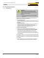
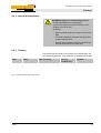
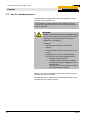
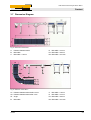
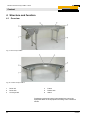
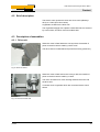
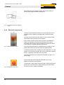
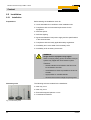
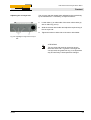
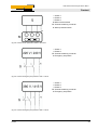
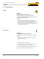
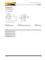
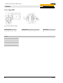
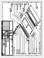
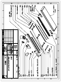
1
Content 2009-09-04 Operating instructions Flat and curved conveyor AM-F / AM-C Dok-ID: 02021 Read the operating instructions before starting work! © GEPPERT-Band GmbH Karl-Heinz-Beckurts-Str. 7 D-52428 Jülich Tel.: +49 (0) 2461-93767-0 Fax: +49 (0) 2461-93767-30 E-Mail: [email protected] Internet: www.geppert-band.de Release: Created by: Kothes! Technische Kommunikation GmbH & Co. KG www.kothes.de 2 09/2009 Flat and curved conveyor AM-F / AM-C Content 1 2 3 4 General....................................................................................5 1.1 Information about the operating instructions .................5 1.2 Explanation of symbols..................................................6 1.3 Limitation of liability........................................................8 1.4 Dismantling and disposal...............................................8 1.5 Copyright........................................................................9 1.6 Warranty conditions .......................................................9 1.7 Customer Service ..........................................................9 1.8 Manufacturer's declaration / Declaration of conformity ......................................................................9 Safety ....................................................................................10 2.1 Customer’s responsibility.............................................10 2.2 Operating personnel ....................................................12 Qualifications ................................................12 2.2.2 Unauthorized persons ..................................13 2.2.3 Training.........................................................13 2.3 Use for intended purpose ............................................14 2.4 Personal protective gear..............................................15 2.5 Special dangers ...........................................................16 2.6 Safety devices .............................................................18 2.7 Securing against switching on .....................................19 2.8 Labelling.......................................................................20 Technical data ......................................................................21 3.1 General information .....................................................21 3.2 Conveyor belt dimensions ...........................................21 3.3 Conveyor speeds.........................................................21 3.4 Connection values .......................................................22 3.5 Operating conditions....................................................22 3.6 Type plate ....................................................................22 3.7 Dimension Diagram .....................................................23 Structure and function ........................................................24 4.1 09/2009 2.2.1 Overview ......................................................................24 3 Flat and curved conveyor AM-F / AM-C Content 5 6 4.2 Brief description .......................................................... 25 4.3 Description of assemblies ........................................... 25 4.3.2 Electrical components ................................. 26 5.1 Safety notes for transport............................................ 28 5.2 Transport inspection.................................................... 29 5.3 Packing ....................................................................... 30 5.4 Transport..................................................................... 30 Installation and commissioning ........................................ 32 6.1 Safety .......................................................................... 32 6.2 Installation ................................................................... 34 6.2.1 Installation.................................................... 34 6.2.2 Connection................................................... 44 Commissioning............................................................ 46 Operation ............................................................................. 47 7.1 8 Drive unit...................................................... 25 Transport, packing and storage ........................................ 28 6.3 7 4.3.1 Shut-down in events of emergency............................. 49 Maintenance......................................................................... 50 8.1 Safety .......................................................................... 50 8.2 Trouble shooting chart ................................................ 52 8.3 Startup after eliminating fault ...................................... 52 8.4 Servicing ..................................................................... 52 9 Replacement Part List......................................................... 53 10 Appendix .............................................................................. 55 10.1 Drive motors................................................................ 55 11 4 10.1.1 Type SN3F................................................... 55 10.1.2 Type SN8F................................................... 56 10.1.3 Type SN9F................................................... 57 Index ..................................................................................... 58 09/2009 Flat and curved conveyor AM-F / AM-C Content Pos: 1.1 /KN2006-SM/Allgemeines/001 1 Allgemeines_Titel @ 8\mod_1142088318714_2.doc @ 75729 1 General Pos: 1.2 /KN2006-SM/Allgemeines/002 1.1 Informationen zur Betriebsanleitung (Gerät) @ 8\mod_1142088382930_2.doc @ 75748 1.1 Information about the operating instructions These operating instructions provide important information on how to work with the device. Strict compliance with all specified safety notes and instructions is a prerequisite for safety at work. Moreover, the accident prevention instructions and general safety regulations applicable at the place of use must also be complied with. Read these operating instructions thoroughly before starting any work! They are part of the product, must always be kept near the device and should be available for the personnel at any time. When passing the device over to a third party, the operating instructions must also be handed over. For better representation of circumstances the illustrations used are not necessarily to scale and may slightly vary from the actual design of the device. Pos: 1.3 /KN2006-SM/Allgemeines/002 1.1.0 Neben dieser Betriebsanleitung gelten die im Anhang befindlichen Betriebsanleitungen @ 8\mod_1142089202762_2.doc @ 75767 The enclosed operating instructions for the installed components apply alongside these operating instructions. Strictly observe the notes contained therein – especially the safety notes! Pos: 1.4 /KN2006-SM/nL.......... Seitenumbruch .......... @ 8\mod_1141998334703_0.doc @ 75491 09/2009 5 Flat and curved conveyor AM-F / AM-C Content Pos: 1.5 /KN2006-SM/Allgemeines/003 1.1 Symbolerklärung @ 8\mod_1142089345047_2.doc @ 75776 1.2 Explanation of symbols Warnings In these operating instructions warnings are identified by symbols. These warnings are introduced by signal words, which express the severity of a danger. Adhere to these warnings and act cautiously in order to avoid accidents, personal injuries and damage to property. DANGER! … indicates an imminently hazardous situation which, if not avoided, will result in death or serious injury. WARNING! … indicates a potentially hazardous situation which, if not avoided, could result in death or serious injury. CAUTION! … indicates a potentially hazardous situation which, if not avoided, may result in minor or moderate injury. CAUTION! … indicates a potentially hazardous situation which, if not avoided, may result in property damage. Hints and recommendations NOTE! … emphasizes useful hints and recommendations as well as information for efficient and trouble-free operation. Pos: 1.6 /KN2006-SM/nL.......... Seitenumbruch .......... @ 8\mod_1141998334703_0.doc @ 75491 6 09/2009 Flat and curved conveyor AM-F / AM-C Content Pos: 1.7 /KN2006-SM/Allgemeines/003 1.1.1 Besondere Sicherheitshinweise_Titel @ 8\mod_1142090242324_2.doc @ 75785 Special safety notes The following symbols are used in connection with the safety notes to highlight particular dangers: Pos: 1.8 /KN2006-SM/Allgemeines/003 1.1.1.0 GEFAHR! Elektrischer Strom! @ 8\mod_1142090323790_2.doc @ 75794 DANGER! Danger to life caused by electric current! … highlights life threatening situations caused by electric current There is a danger of serious injury or death if the safety notes are not complied with. The work to be performed must only be carried out by qualified electricians. Pos: 1.9 /KN2006-SM/nL---------- Abschnittsende ---------- @ 8\mod_1141997892953_0.doc @ 75473 Pos: 1.10 /KN2006-Projekte/Geppert/Allgemeines/1.1.1.0 Quetschgefahr @ 29\mod_1170756425511_2.doc @ 338153 DANGER! Danger of crushing and trapping from moving chains and rotating axles! … indicates dangerous situations due to moving chains and rotating axles. If the safety instructions are not followed, there is a danger of slight to serious injuries. Pos: 1.11 /KN2006-SM/nL.......... Seitenumbruch .......... @ 8\mod_1141998334703_0.doc @ 75491 09/2009 7 Flat and curved conveyor AM-F / AM-C Content Pos: 1.12 /KN2006-SM/Allgemeines/005 1.1 Haftungsbeschränkung @ 8\mod_1142091543501_2.doc @ 75812 1.3 Limitation of liability All information and notes in this manual were compiled under due consideration of valid standards and regulations, the present status of technology and our years of knowledge and experience. The manufacturer can not be made liable for damage resulting from: z disregarding these instructions z unintended use z employment of untrained personnel z unauthorized conversions z technical modifications z use of unapproved spare parts In case of customised versions the actual scope of delivery can vary from the explanations and representations in these instructions, because of the utilization of additional options or due to latest technical changes. Apart from this, the obligations agreed upon in the delivery contract, the General Terms of Business and the delivery conditions of the manufacturer and the legal regulations valid at the time of contract do apply. Pos: 1.13 /KN2006-SM/Allgemeines/005 1.1.0 Technische Änderungen vorbehalten --> Wenn Kunde verlangt! @ 12\mod_1142965766069_2.doc @ 80003 We reserve the right to make technical modifications in order to improve usability. Pos: 1.14 /KN2006-SM/nL---------- Abschnittsende ---------- @ 8\mod_1141997892953_0.doc @ 75473 Pos: 1.15 /KN2006-Projekte/Geppert/Allgemeines/1.1 Demontage und Entsorgung, allg. (Kurzfassung) @ 30\mod_1171042860155_3.doc @ 344715 1.4 Dismantling and disposal If no return or disposal agreement was made, dismantle the equipment properly following the safety instructions in these operating instructions, and dispose of it environmentally correctly. Before dismantling: Switch off the power supply and secure against reconnection. Then physically separate the supply cables, and discharge stored residual energy. Remove and dispose environmentally correctly of operating and auxiliary materials as well as residual production materials. On disposal Send dismantled components for recycling. – Send residual metal components for scrap. – Give plastic parts in for recycling. – Dispose of other components according to their material properties. Pos: 1.16 /KN2006-SM/nL.......... Seitenumbruch .......... @ 8\mod_1141998334703_0.doc @ 75491 8 09/2009 Flat and curved conveyor AM-F / AM-C Content Pos: 1.17 /KN2006-SM/Allgemeines/006 1.1 Urheberschutz (Betriebsanleitung, Gerät) @ 8\mod_1142092015791_2.doc @ 75821 1.5 Copyright Treat the operating instructions confidentially. They are only intended for persons working with or on the device. Passing these operating instructions on to third parties without the written consent of the manufacturer is not permitted. NOTE! The contents of these instructions, texts, drawings, pictures and other representations are protected by copyright law subject to industrial property rights. Any misuse is punishable. Reproduction of any kind – even in form of excerpts – as well as the use and/or disclosure of the contents without the written consent of the manufacturer is not permitted. Violations oblige to compensation. The right for further claims remains reserved. Pos: 1.18 /KN2006-SM/nL---------- Abschnittsende ---------- @ 8\mod_1141997892953_0.doc @ 75473 Pos: 1.19 /KN2006-SM/Allgemeines/011 1.1 Garantiebestimmungen_Titel @ 9\mod_1144054714613_2.doc @ 84758 1.6 Warranty conditions Pos: 1.20 /KN2006-SM/Allgemeines/011 1.1.0 Garantie als separates Dokument in den Verkaufsunterlagen @ 9\mod_1144054766031_2.doc @ 84765 The warranty conditions are attached to the sales documents as a separate document. Pos: 1.21 /KN2006-SM/nL---------- Abschnittsende ---------- @ 8\mod_1141997892953_0.doc @ 75473 Pos: 1.22 /KN2006-SM/Allgemeines/010 1.1 Kundendienst_Titel+Text @ 8\mod_1142095433275_2.doc @ 75902 1.7 Customer Service Our Customer Service is always available for technical information. Notes on the responsible contact partner are on call by phone, fax, e-mail or via internet, see address of manufacturer on page 2. Apart from that, our members of staff are permanently interested in receiving new information and experience resulting from the use of our products and which could be of great value for future improvements. Pos: 1.23 /KN2006-SM/nL---------- Abschnittsende ---------- @ 8\mod_1141997892953_0.doc @ 75473 Pos: 1.24 /KN2006-Projekte/Geppert/Allgemeines/1.1 Herstellererklärung_Konformitätserklärung_Titel @ 29\mod_1170258618138_2.doc @ 334273 1.8 Manufacturer's declaration / Declaration of conformity Pos: 1.25 /KN2006-Projekte/Geppert/Allgemeines/1.1.1 Herstellererklärung_Konformitätserklärung @ 29\mod_1170259301653_2.doc @ 334303 If the equipment has not been provided ready to connect, the manufacturer's declaration is present as a separate document. If the equipment has been provided ready to connect, the declaration of conformity is present as a separate document. Pos: 2.1 /FI/.......... Seitenumbruch .......... @ 0\mod272_2.doc @ 1523 09/2009 9 Flat and curved conveyor AM-F / AM-C Content Pos: 2.2 /KN2006-SM/Sicherheit/001 1 Sicherheit_Titel @ 8\mod_1142425976781_2.doc @ 77463 2 Safety Pos: 2.3 /KN2006-SM/Sicherheit/001 1.0 Einführung @ 8\mod_1142427208593_2.doc @ 77492 This paragraph provides you with an overview of all important safety aspects for optimal protection of personnel as well as safe and trouble-free operation. Disregarding the operating instructions and safety regulations specified in this manual may result in considerable danger. Pos: 2.4 /KN2006-SM/nL---------- Abschnittsende ---------- @ 8\mod_1141997892953_0.doc @ 75473 Pos: 2.5 /KN2006-SM/Sicherheit/003 1.1 Verantwortung des Betreibers_Titel @ 8\mod_1142428931187_2.doc @ 77569 2.1 Customer’s responsibility Pos: 2.6 /KN2006-Projekte/SIHI-Sterling/UNI-Ordner/Sicherheit/003 Verantwortung des Betreibers/Verantwortung Betreiber allg. Teil (Gerät) @ 10\mod_1145980710449_2.doc @ 93965 The device is used for commercial purposes. The company operating the device is thus subject to the legal obligations concerning industrial safety. The safety, accident prevention and environmental protection regulations applicable for the area of application of the device must be complied with, alongside the safety notes specified in these operating instructions. The customer must, in particular: keep himself informed about the valid industrial safety regulations. determine other dangers that result from special working conditions at the place of use in form of a risk analysis. include the necessary behaviour requirements for operation of the device at the place of use into operating instructions. check the device over the entire period of use, to make sure that the operating instructions drawn up by him always conform with the latest technical standards. match the operating instructions to latest regulations, standards and work conditions - if this should become necessary. unambiguously assign responsibilities for installation, operation, maintenance and cleaning of the device make sure that all members of staff, who work on or with the device, have read and understood these operating instructions. Apart from this, the customer must train and inform his personnel about work on and with the device and potential dangers at regular intervals. Moreover, the customer is responsible for maintaining the device in technically mint condition. adhering to the specified maintenance intervals. 10 09/2009 Flat and curved conveyor AM-F / AM-C Content checking all safety features at regular intervals for completeness and function. Pos: 2.7 /FI/.......... Seitenumbruch .......... @ 0\mod272_2.doc @ 1523 09/2009 11 Flat and curved conveyor AM-F / AM-C Content Pos: 2.8 /KN2006-SM/Sicherheit/004 Personal/004 1.1 Personalanforderungen_Titel @ 8\mod_1142431816578_2.doc @ 77627 2.2 Operating personnel Pos: 2.9 /KN2006-SM/Sicherheit/004 Personal/004 1.1.1 Personal Qualifikationen @ 13\mod_1152880813359_2.doc @ 148323 2.2.1 Qualifications WARNING! Danger of injury if insufficiently qualified! Improper operation can lead to serious personal injuries or property damage. Therefore: – Have all activities performed only by qualified personnel. The following qualifications are specified for different areas of activity listed in the operating instructions. Pos: 2.10 /KN2006-SM/Sicherheit/004 Personal/004 1.1.0 Unterwiesene Person/Fachpersonal @ 13\mod_1152880944937_2.doc @ 148342 Pos: 2.11 /KN2006-SM/Sicherheit/004 Personal/004 1.1.0 Elektrofachkraft @ 13\mod_1152885134593_2.doc @ 148541 An instructed person has been instructed by the customer in an orientation session on the assigned tasks and possible dangers in case of improper behavior. Qualified personnel based on their professional training, know-how and experience as well as knowledge of the applicable standards and regulations is able to perform assigned work activities and to detect and avoid possible dangers on their own. A professional electrician based on his/her professional training, know-how and experience as well as knowledge of the applicable standards and regulations is able to perform work on electrical systems and to detect and avoid possible dangers on his/her own. The professional electrician has been trained for the special location where he/she works and knows the relevant standards and regulations. Pos: 2.12 /KN2006-SM/Sicherheit/004 Personal/004 1.1.0 ...zuverlässiges Personal... @ 13\mod_1152892110812_2.doc @ 148628 Only persons of whom it may be expected that they perform their work reliably are permitted as personnel. Persons whose reaction capability is impaired, e.g. through drugs, alcohol or medication are not permitted. When selecting the personnel, the stipulations regarding age and occupation applying at the location must be observed. Pos: 2.13 /KN2006-SM/nL---------- Abschnittsende ---------- @ 8\mod_1141997892953_0.doc @ 75473 12 09/2009 Flat and curved conveyor AM-F / AM-C Content Pos: 2.14 /KN2006-SM/Sicherheit/004 Personal/004 1.1.1 Unbefugte @ 13\mod_1152892272765_2.doc @ 148637 2.2.2 Unauthorized persons WARNING! Danger for unauthorized persons! Unauthorized persons not meeting the requirements outlined here are not aware of the dangers in the work area. Therefore: – Keep unauthorized persons away from the work area. – If in doubt, address the persons and direct them to leave the work area. – Interrupt work activities as long as unauthorized persons are present in the work area. Pos: 2.15 /KN2006-SM/nL---------- Abschnittsende ---------- @ 8\mod_1141997892953_0.doc @ 75473 Pos: 2.16 /KN2006-SM/Sicherheit/004 Personal/004 1.1.1 Unterweisung @ 12\mod_1142946308736_2.doc @ 79821 2.2.3 Training Personnel must be trained by the operator on a regular basis. For record-keeping purposes, a log of training conducted must be kept. Date Name Type of training Training conducted by Signature Fig. 1: Sample training log (master copy) Pos: 2.17 /FI/.......... Seitenumbruch .......... @ 0\mod272_2.doc @ 1523 09/2009 13 Flat and curved conveyor AM-F / AM-C Content Pos: 2.18 /KN2006-Projekte/Geppert/Sicherheit/1.1 Bestimmungsgemäße Verwendung (Gerät) --> AM_F_C @ 28\mod_1169200735559_2.doc @ 327447 2.3 Use for intended purpose The equipment is designed and constructed exclusively for the purpose of use described here. The equipment is used exclusively for the transport of piece goods and packages for internal use within operating areas not prone to explosion. WARNING! Danger if used other than for intended purpose! Any use other than for the intended purpose and/or other type of use of the equipment can lead to dangerous circumstances. Therefore: – Use the equipment only for its intended purpose. – Strictly follow all directions in these instructions for use. – In particular, do not do any of the following: They count as use not for intended purpose: – Transport of bulk materials. – Transport of piece goods whose weight exceeds the maximum weight given in the technical data. – Transport or carriage of people or animals. – Use in explosion-prone areas. Claims of any type for damages resulting from use other than for intended purpose are excluded. The operator alone is responsible for all damages resulting from use other than for intended purpose. Pos: 2.19 /FI/.......... Seitenumbruch .......... @ 0\mod272_2.doc @ 1523 14 09/2009 Flat and curved conveyor AM-F / AM-C Content Pos: 2.20 /KN2006-SM/Sicherheit/006 Persönliche Schutzausstattung/006 1.1 Persönliche Schutzausrüstung @ 8\mod_1143360751363_2.doc @ 80982 2.4 Personal protective gear Wearing of personal protective gear is required when working to minimize the health hazards. Always wear the protective gear that is necessary for the respective task when working. Follow the instructions on personal protective gear that are posted in the work area. Pos: 2.21 /KN2006-SM/Sicherheit/006 Persönliche Schutzausstattung/006 1.1.0_1 Grundsätzlich zu tragen_Titel @ 8\mod_1143360998458_2.doc @ 80991 Wear generally Generally wear for all kind of work: Pos: 2.22 /KN2006-SM/Sicherheit/006 Persönliche Schutzausstattung/Arbeitsschutzkleidung @ 8\mod_1143362598709_2.doc @ 81063 Protective clothing are tight fitting working clothes with low tear resistance, with light sleeves and without any sticking out parts. These clothes are mainly a protection against being caught by moving machine parts. Do not wear rings, chains, necklaces and other jewellery. Pos: 2.23 /KN2006-SM/Sicherheit/006 Persönliche Schutzausstattung/Sicherheitsschuhe @ 8\mod_1143362886212_2.doc @ 81072 Safety boots to protect against heavy parts falling down or slipping on slippery ground. Pos: 2.24 /KN2006-SM/Sicherheit/006 Persönliche Schutzausstattung/Schutzhandschuhe @ 8\mod_1143361962043_2.doc @ 81045 Protective gloves to protect the hand against friction, graze, punctures or deep cuts as well as contact with hot surfaces. Pos: 2.25 /KN2006-SM/nL---------- Abschnittsende ---------- @ 8\mod_1141997892953_0.doc @ 75473 Pos: 2.26 /KN2006-SM/Sicherheit/006 Persönliche Schutzausstattung/006 1.1.0_2 Bei besonderen Arbeiten zu tragen_Titel @ 18\mod_1143361122656_2.doc @ 81000 Wear personal protective gear for special tasks When performing special tasks it is necessary to wear personal protective gear. This personal protective gear will be separately specified in the chapters of this manual. This special protective gear is explained below. Pos: 2.27 /KN2006-Projekte/Geppert/Sicherheit/Haarnetz @ 29\mod_1170070023546_2.doc @ 332177 Hairnet to protect long hair from being caught, wrapped up in, or drawn into moving parts. Pos: 2.28 /FI/.......... Seitenumbruch .......... @ 0\mod272_2.doc @ 1523 09/2009 15 Flat and curved conveyor AM-F / AM-C Content Pos: 2.29 /KN2006-SM/Sicherheit/007 Besondere Gefahren/007 1.1 Besondere Gefahren_Titel und Einleitung @ 8\mod_1143366409048_2.doc @ 81172 2.5 Special dangers The following section lists the residual risks that have been determined by the risk analysis. Heed the safety instructions listed here, and the warning instructions in subsequent chapters of this guide, to reduce health hazards and to avoid dangerous situations. Pos: 2.30 /KN2006-SM/nL---------- Abschnittsende ---------- @ 8\mod_1141997892953_0.doc @ 75473 Pos: 2.31 /KN2006-SM/Sicherheit/007 Besondere Gefahren/Elektrischer Strom @ 8\mod_1143366795746_2.doc @ 81190 Electric Current DANGER! Danger to life caused by electric current! Touching conductive parts causes a direct danger to life. Damage to insulations or individual components can cause danger to life. Therefore: – In the event of damage to insulation switch off the power supply immediately and have the defective parts repaired. – Work on the electric system must be carried out only by skilled electricians. – De-energize the machine for all work on the electrical system. – Before maintenance, cleaning or repair work, switch off the power supply and secure it against being switched on again. – Do not bridge fuses or make them ineffective. When changing fuses make sure you use the correct amperage. – Keep moisture away from conductive parts. This can cause short circuit. Pos: 2.32 /KN2006-SM/nL---------- Abschnittsende ---------- @ 8\mod_1141997892953_0.doc @ 75473 16 09/2009 Flat and curved conveyor AM-F / AM-C Content Pos: 2.33 /KN2006-Projekte/Geppert/Sicherheit/Besondere Gefahren/Fördergut (AM_F_C) @ 29\mod_1170262050428_2.doc @ 334349 Transported material ATTENTION! Danger of injury from transported material! Transported material on the conveyor belt can cause injuries. Therefore: – Ensure that material is loaded correctly on the conveyor belt. – Choose sufficient separation between the transported materials to prevent the danger of being crushed. – Position the transported material on the conveyor belt in such a way that it cannot fall off during transport. – Ensure that there is suitable guiding equipment at the end of the conveyor belt (e.g. edge protection straps, funnel trap). – Wear personal protective equipment in the working area. Pos: 2.34 /KN2006-SM/nL---------- Abschnittsende ---------- @ 8\mod_1141997892953_0.doc @ 75473 Pos: 2.35 /KN2006-Projekte/Geppert/Sicherheit/Besondere Gefahren/Transportkette (AM_F_C) @ 29\mod_1170262978262_2.doc @ 334481 Conveyor belt and return rollers WARNING! Danger of crushing and trapping from moving conveyor belt and rotating return rollers. A moving conveyor belt and rotating return rollers can draw in parts of clothing and long hair, or trap body parts and cause light to heavy injuries. Therefore: – Do not reach into moving conveyor belts. – Do not reach into rotating return rollers. – Do not reach into gaps between conveyor belts, frames, and other parts of the equipment. – Observe the warning symbols in the working area. – Carry out work on the equipment only when it is stopped. – Wear personal protective equipment in the working area. Pos: 2.36 /KN2006-SM/nL---------- Abschnittsende ---------- @ 8\mod_1141997892953_0.doc @ 75473 09/2009 17 Flat and curved conveyor AM-F / AM-C Content Pos: 2.37 /KN2006-SM/Sicherheit/008 Sicherheitseinrichtungen/008 1.1 Sicherheitseinrichtungen @ 8\mod_1143382649171_2.doc @ 81566 2.6 Safety devices WARNING! Malfunctioning safety devices may pose a fatal risk! Safety devices must be intact in order to guarantee safety. Therefore: – Before starting work, check that the safety devices are fully functional and correctly installed. – Never disable safety devices. – Take care to ensure that safety devices such as emergency stops, emergency trip wires etc. are always accessible. NOTE! See the "Structure and function" chapter for further information on the location of safety devices. Pos: 2.38 /KN2006-SM/nL---------- Abschnittsende ---------- @ 8\mod_1141997892953_0.doc @ 75473 Pos: 2.39 /KN2006-Projekte/Geppert/Sicherheit/Kein eingener Not-Aus (AM_F_C) @ 29\mod_1170331731647_2.doc @ 334823 Integration into an emergency stop concept is required If the equipment is not delivered ready to connect, or it is destined for use as part of a system, it has no control of its own and no autonomous emergency stop function. Before the equipment is commissioned, install emergency stop equipment and integrate it into the safety function of the equipment control system. Connect the emergency stop equipment in such a way that if the power supply is interrupted, or the power supply is activated after an interruption, dangerous situations for humans or materials cannot arise. The emergency stop equipment must be easily accessible at all times. Pos: 2.40 /KN2006-SM/nL---------- Abschnittsende ---------- @ 8\mod_1141997892953_0.doc @ 75473 18 09/2009 Flat and curved conveyor AM-F / AM-C Content Pos: 2.41 /KN2006-SM/Sicherheit/009 1.1 Sichern gegen Wiedereinschalten_Titel+Text @ 9\mod_1144435859202_2.doc @ 86860 2.7 Securing against switching on DANGER! Danger to life caused by uncontrolled reconnection of electrical power supply! There is a risk of the electric power supply being switched on again when working in a danger zone. This creates danger to the life of persons in the danger zone. Therefore: – Follow the instructions for securing the equipment against switching on in the sections of these operating instructions. – To secure against switching on again follow the sequence described below. Switch secured with padlock on: …….. at …… o’clock DO NOT SWITCH ON Securing against switching on: 1. Switch off the electric power supply. 2. If possible secure the switch with a padlock and attach a clearly visible warning label to the switch, as shown in Fig. 2. 3. Have the key stored with the staff member nominated on the label. 4. If a switch cannot be secured with a padlock, stand up a sign as shown in Fig. 3. 5. After all work has been completed, make sure that there are no persons in the danger zone. 6. Make sure that all protective device are correctly in place and fully functional. 7. Remove the sign only if this has been confirmed. The padlock must be removed only by: ………………… after it has been ensured that no persons are inside the danger zone. Fig. 2 Switched off on: …….. at …… o’clock DO NOT SWITCH ON The equipment may be switched on only by: ………………… after it has been ensured that no persons are inside the danger zone. Fig. 3 Pos: 2.42 /FI/.......... Seitenumbruch .......... @ 0\mod272_2.doc @ 1523 09/2009 19 Flat and curved conveyor AM-F / AM-C Content Pos: 2.43 /KN2006-Projekte/Geppert/Sicherheit/1.1 Beschilderung @ 29\mod_1170779396205_2.doc @ 338973 2.8 Labelling Depending on the working conditions in the area of operation, the following symbols and signs are applied to the equipment. They apply to the immediate neighbourhood in which they are displayed. WARNING! Danger of injury if symbols are illegible! With the passage of time, labels and signs can become dirty or otherwise illegible. Therefore: – Keep all safety, warning, and operational notices easily legible at all times. – Replace damaged signs or labels immediately. In areas of manual operations In areas where there are electrical connections On the gear drive (max. Drehm. = maximal torque) Pos: 3.1 /KN2006-SM/nL.......... Seitenumbruch .......... @ 8\mod_1141998334703_0.doc @ 75491 20 09/2009 Flat and curved conveyor AM-F / AM-C Content Pos: 3.2 /KN2006-SM/Technische Daten/001 1 Technische Daten_Titel @ 8\mod_1143124628960_2.doc @ 80563 3 Technical data Pos: 3.3 /KN2006-Projekte/Geppert/Technische Daten/1.1 Hinweis @ 31\mod_1172764401119_2.doc @ 363943 ATTENTION! Every conveyor system is individually adapted to its conditions of use in terms of its dimensions, conveyor speed, and weight of goods conveyed. The following details should therefore be seen as standard values. Pos: 3.4 /KN2006-SM/nL---------- Abschnittsende ---------- @ 8\mod_1141997892953_0.doc @ 75473 Pos: 3.5 /KN2006-SM/Technische Daten/001 1.1 Allgemeine Angaben_Titel @ 9\mod_1143988260287_2.doc @ 84212 3.1 General information Pos: 3.6 /KN2006-Projekte/Geppert/Technische Daten/1.1.0 Allgemeine Angaben @ 29\mod_1170510146090_2.doc @ 336559 Value AM-F / AM-C Weight [kg] 30…250 Maximum weight to be conveyed [kg] 50 Length of conveyor belt [m] 0,5…6 Angle [°] (only AM-C) 15 to 180 Pos: 3.7 /KN2006-SM/nL---------- Abschnittsende ---------- @ 8\mod_1141997892953_0.doc @ 75473 Pos: 3.8 /KN2006-Projekte/Geppert/Technische Daten/1.1 Förderkettenabmessungen_Titel @ 30\mod_1170946557955_2.doc @ 342239 3.2 Conveyor belt dimensions Pos: 3.9 /KN2006-Projekte/Geppert/Technische Daten/1.1.0 Förderkettenabmessungen @ 30\mod_1170946697694_2.doc @ 342251 Conveyor belt width [mm] 152 305 457 610 Inner radius in relation to belt width [mm] (only AM-C) 350 700 1050 1400 Pos: 3.10 /KN2006-SM/nL---------- Abschnittsende ---------- @ 8\mod_1141997892953_0.doc @ 75473 Pos: 3.11 /KN2006-Projekte/Geppert/Technische Daten/1.1 Fördergeschwindigkeiten_Titel @ 30\mod_1170945422942_2.doc @ 341965 3.3 Conveyor speeds Pos: 3.12 /KN2006-Projekte/Geppert/Technische Daten/1.1.0 Fördergeschwindigkeiten @ 30\mod_1170945476865_2.doc @ 342137 Equipment with constant conveyor speed [m/min] 6,5 12,1 18,3 24,4 36,6 52,3 Equipment with variable conveyor speed [m/min] 2,6…9,5 4,9…17,8 7,3…26,7 9,8…35,6 14,7…53,4 21…76,3 Pos: 3.13 /KN2006-SM/nL.......... Seitenumbruch .......... @ 8\mod_1141998334703_0.doc @ 75491 09/2009 21 Flat and curved conveyor AM-F / AM-C Content Pos: 3.14 /KN2006-SM/Technische Daten/002 1.1 Anschlusswerte_Titel @ 9\mod_1143988625840_2.doc @ 84226 3.4 Connection values Pos: 3.15 /KN2006-Projekte/Geppert/Technische Daten/1.1.0 Anschlußwerte @ 29\mod_1170510010618_2.doc @ 336547 Value Motor types SN3F SN8F SN9F Voltage [V] at 50 Hz 380 380 380 Current requirement [A] 0,7 1,6 1,2 Power requirement [W] 180 550 370 For further details of motor data please refer to the appendix. Pos: 3.16 /KN2006-SM/nL---------- Abschnittsende ---------- @ 8\mod_1141997892953_0.doc @ 75473 Pos: 3.17 /KN2006-SM/Technische Daten/003 1.1 Betriebsbedingungen_Titel @ 9\mod_1143989042992_2.doc @ 84240 3.5 Operating conditions Pos: 3.18 /KN2006-Projekte/Geppert/Technische Daten/1.1.0 Betriebsbedingungen @ 29\mod_1170509668935_2.doc @ 336523 Environment Value AM-F / AM-C Temperature range [°C] Relative humidity, maximum [%] Duration Value -10…60 95 AM-F / AM-C Maximum period of continuus operation Suitable for permanent operation Pos: 3.19 /KN2006-SM/nL---------- Abschnittsende ---------- @ 8\mod_1141997892953_0.doc @ 75473 Pos: 3.20 /KN2006-SM/Technische Daten/008 1.1 Typenschild_Titel @ 9\mod_1144045129972_2.doc @ 84413 3.6 Type plate Pos: 3.21 /KN2006-Projekte/Geppert/Technische Daten/1.1.0 Typenschild --> (AM-F / AM-C) @ 29\mod_1170072711628_2.doc @ 332329 The manufacturer's plate is located on the drive unit and contains the following details: Fig. 4: Manufacturer's plate 1 2 3 4 5 6 Maker Year of construction No. of phases Supply voltage and frequency Manufacturing number Type Pos: 3.22 /KN2006-SM/nL.......... Seitenumbruch .......... @ 8\mod_1141998334703_0.doc @ 75491 22 09/2009 Flat and curved conveyor AM-F / AM-C Content Pos: 3.23 /KN2006-SM/Technische Daten/007 1.1 Maßblatt_Titel @ 12\mod_1143990330418_2.doc @ 84296 3.7 Dimension Diagram Pos: 3.24 /KN2006-Projekte/Geppert/Technische Daten/1.1.0 Maßblatt @ 29\mod_1170510364549_2.doc @ 336571 Fig. 5: Dimension sheet AM-F A: B: C: Distance between axles Belt width Belt width + 18 mm D: Belt width + 44 mm D1: Belt width + 99 mm D2: Belt width + 274 mm Fig. 6 dimension sheet AM-C A1: A2: W: B: Distance between axles before curve Distance between axles after curve Angle Belt width C: D: D1: D2: Belt width + 18 mm Belt width + 44 mm Belt width + 99 mm Belt width + 274 mm Pos: 4.1 /KN2006-SM/nL.......... Seitenumbruch .......... @ 8\mod_1141998334703_0.doc @ 75491 09/2009 23 Flat and curved conveyor AM-F / AM-C Content Pos: 4.2 /KN2006-SM/Aufbau und Funktion/001 1 Aufbau und Funktion_Titel @ 8\mod_1143713625726_2.doc @ 83163 4 Structure and function Pos: 4.3 /KN2006-SM/Aufbau und Funktion/002 1.1 Übersicht_Titel @ 9\mod_1144046023684_2.doc @ 84434 4.1 Overview Pos: 4.4 /KN2006-Projekte/Geppert/Aufbau und Funktion/1.1.0 Übersicht --> (AM-F / AM-C) @ 29\mod_1170073494988_2.doc @ 332361 Fig. 7: Flat conveyor AM-F Fig. 8: Curved conveyor AM-C 1 2 3 Drive unit Drive axle Conveyor belt 4 5 6 Frame Return axle Stand Furthermore, electrical control components form part of the equipment fitted on the equipment according to the customer's wishes. Pos: 4.5 /KN2006-SM/nL.......... Seitenumbruch .......... @ 8\mod_1141998334703_0.doc @ 75491 24 09/2009 Flat and curved conveyor AM-F / AM-C Content Pos: 4.6 /KN2006-SM/Aufbau und Funktion/003 1.1 Kurzbeschreibung_Titel @ 9\mod_1144048508654_2.doc @ 84497 4.2 Brief description Pos: 4.7 /KN2006-Projekte/Geppert/Aufbau und Funktion/1.1.0 Kurzbeschreibung @ 29\mod_1170080773620_2.doc @ 332395 The electric motor powers the drive axle via a clutch (sideways drive) or a chain (drive from below). Cogwheels are fitted to the drive axle. The cogwheels engage with a plastic module belt which is returned by a return axle, and which forms an endless belt. Pos: 4.8 /KN2006-SM/nL---------- Abschnittsende ---------- @ 8\mod_1141997892953_0.doc @ 75473 Pos: 4.9 /KN2006-SM/Aufbau und Funktion/004 1.1 Baugruppenbeschreibung_Titel @ 9\mod_1144046217018_2.doc @ 84448 4.3 Description of assemblies Pos: 4.10 /KN2006-Projekte/Geppert/Aufbau und Funktion/1.1.1 Baugruppenbeschreibung_Antriebseinheit_Titel @ 29\mod_1170082098596_2.doc @ 332497 4.3.1 Drive unit Pos: 4.11 /KN2006-Projekte/Geppert/Aufbau und Funktion/Antriebseinheit @ 29\mod_1170088762240_2.doc @ 332509 When the motor is fitted below the conveyor belt, the transfer of power to the drive axle is made by a drive chain. The drive chain is located behind a protective housing (chain box). Fig. 9: Drive unit below When the motor is fitted next to the conveyor belt, the transfer of power to the drive axle is made by a clutch. The clutch is located in a clutch housing between the motor and the drive axle. It consists of two cogwheels which are connected via the clutch sleeve. Fig. 10: Drive unit to the side 09/2009 25 Flat and curved conveyor AM-F / AM-C Content When fitting the motor sideways next to the conveyor belt, the motor can be flange mounted in steps of 90°. Fig. 11: Installation options for sideways drive Pos: 4.12 /KN2006-SM/nL---------- Abschnittsende ---------- @ 8\mod_1141997892953_0.doc @ 75473 Pos: 4.13 /KN2006-Projekte/Geppert/Aufbau und Funktion/1.1.1 Baugruppenbeschreibung_Elektrische Kompopnenten_Titel @ 29\mod_1170515082950_2.doc @ 336619 4.3.2 Electrical components Pos: 4.14 /KN2006-Projekte/Geppert/Aufbau und Funktion/Motorschutzschalter @ 29\mod_1170515292440_2.doc @ 336643 Conveyor systems which are ready to connect and which have a constant conveyor speed are equipped with a motor protection switch. Conveyor systems which are not ready to connect must be fitted with suitable motor protection by the operator. Every motor protection switch has the function of protecting the motor from overload. This means that damage to the motor is impossible if the conveyor belt is blocked for mechanical reasons. In this case the converter switches the power off. Fig. 12: Motor protection switch The motor protection switch is equipped with an emergency stop switch which allows the conveyor belt to be stopped quickly. The protection switch has a restart lock if the voltage falls, i.e. if the power is cut off and reconnected, the conveyor belt will not start on its own. A separate start button must be pressed. The motor protection switch should be connected to a 380 V / 3~ / 50 Hz supply. Pos: 4.15 /KN2006-SM/nL---------- Abschnittsende ---------- @ 8\mod_1141997892953_0.doc @ 75473 Pos: 4.16 /KN2006-Projekte/Geppert/Aufbau und Funktion/Not-Aus-Schalter @ 29\mod_1170515247439_2.doc @ 336631 All conveyor belts can be optionally fitted with one or more additional emergency stop switches. Fig. 13: Emergency stop switch The emergency stop switches are connected in series between the power source and the motor, so that activating any switch stops the whole conveyor system immediately. Pos: 4.17 /KN2006-SM/nL---------- Abschnittsende ---------- @ 8\mod_1141997892953_0.doc @ 75473 26 09/2009 Flat and curved conveyor AM-F / AM-C Content Pos: 4.18 /KN2006-Projekte/Geppert/Aufbau und Funktion/Frequenzumrichter @ 29\mod_1170332857831_2.doc @ 334835 Conveyor systems which are ready to connect and which have an adjustable conveyor speed are equipped with a frequency converter. For motors up to 250 Watt power, the GB-FU 250 unit is used. For motors from 250 to 370 Watt, the GB-FU 370 unit is used. Motors with a power greater than 370 Watt are provided with a frequency converter specially matched to the motor. Every frequency converter also has the function of protecting the motor from overload. This means that damage to the motor is impossible if the conveyor belt is blocked for mechanical reasons. In this case the converter switches the power off. Frequency converters should be connected to a 230 V ~ / 50 Hz supply. Converters have separate operating instructions provided with every delivery. Fig. 14: Frequency converter The converter has an emergency stop switch to stop the conveyor belt quickly in case of danger. The frequency converter has a restart lock if the voltage falls, i.e. if the power is cut off and reconnected, the conveyor belt will not start on its own. A separate start button must be pressed. ATTENTION! Damage if the frequency converter is incorrectly programmed! Incorrect programming of the frequency converter can result in damage. Therefore: – The programming may be changed only by trained personnel and after contacting the manufacturer. Pos: 5.1 /KN2006-SM/nL.......... Seitenumbruch .......... @ 8\mod_1141998334703_0.doc @ 75491 09/2009 27 Flat and curved conveyor AM-F / AM-C Content Pos: 5.2 /KN2006-SM/Transport, Verpackung und Lagerung/001 1 Transport, Verpackung und Lagerung_Titel @ 9\mod_1144048567385_2.doc @ 84504 5 Transport, packing and storage Pos: 5.3 /KN2006-SM/Transport, Verpackung und Lagerung/002 1.1 Sicherheitshinweise für den Transport_Titel @ 9\mod_1144048644190_2.doc @ 84511 5.1 Safety notes for transport Pos: 5.4 /KN2006-SM/Transport, Verpackung und Lagerung/002 1.1.0 Vorsicht Transportschäden bei unsachgemäßem Transport @ 12\mod_1144051344560_2.doc @ 84539 Improper transport CAUTION! Improper transport can result in damage! Improper transport can cause extensive material damage. Therefore: – When unloading the packing units upon delivery and during in-house transport, exercise caution and observe the symbols on the package. – Use only the provided attachment points. – Do not remove packaging material until units are ready for assembly. Pos: 5.5 /KN2006-SM/nL---------- Abschnittsende ---------- @ 8\mod_1141997892953_0.doc @ 75473 Pos: 5.6 /KN2006-SM/Transport, Verpackung und Lagerung/002 1.1.0 Außermittiger Schwerpunkt @ 12\mod_1144502588366_2.doc @ 87475 Eccentric Center of Gravity WARNING! Danger of falling due to eccentric center of gravity! Packing crates can have an eccentric center of gravity. The wrong kind sling gear attachment can tilt the packing crate and cause life-threatening injuries. Consequently: – Comply with the instructions marked on packing crates. – Attach the crane hook in such a manner that it is over the center of gravity. – Lift carefully and observe if the load tips. If required change the position of the sling gear. Pos: 5.7 /KN2006-SM/nL---------- Abschnittsende ---------- @ 8\mod_1141997892953_0.doc @ 75473 28 09/2009 Flat and curved conveyor AM-F / AM-C Content Pos: 5.8 /KN2006-SM/Transport, Verpackung und Lagerung/002 1.1.0 Warnung! Lebensgefahr durch schwebende Lasten @ 12\mod_1144048709603_2.doc @ 84518 Suspended Loads WARNING! Life-threatening hazard due to suspended loads! When lifting loads a life-threatening hazard is posed by falling loads or swinging parts. Consequently: – Never position yourself under a suspended load! – Heed the instructions concerning the intended lifting points. – Do not attach to projecting machine components or to the eyes of attached components; ensure that the sling gear is securely seated. – Only use approved lifting gear and slings with sufficient bearing capacity. – Do not use frayed or scored rope or belts. – Do not lay ropes and belts on sharp edges and corners, do not knot or twist ropes and belts. Pos: 5.9 /KN2006-SM/nL---------- Abschnittsende ---------- @ 8\mod_1141997892953_0.doc @ 75473 Pos: 5.10 /KN2006-SM/Transport, Verpackung und Lagerung/004 1.1 Transportinspektion_Titel @ 9\mod_1144054094956_2.doc @ 84694 5.2 Transport inspection Pos: 5.11 /KN2006-SM/Transport, Verpackung und Lagerung/004 1.1.0 Transportinspektion - Inhalt, Kurzform @ 9\mod_1144054141858_2.doc @ 84751 Check the delivery immediately on receipt for completeness and transport damage. If externally detectable transport damage is found, proceed as follows: Do not accept the delivery, or only with reservation. Record the extent of transport damage in the transport documents or on the delivery note of the forwarding agent. Start complaints procedure. NOTE! Claim any damage as soon as it is detected. Compensation claims can only be submitted within the applicable complaints periods. Pos: 5.12 /KN2006-SM/nL---------- Abschnittsende ---------- @ 8\mod_1141997892953_0.doc @ 75473 09/2009 29 Flat and curved conveyor AM-F / AM-C Content Pos: 5.13 /KN2006-SM/Transport, Verpackung und Lagerung/005 1.1 Verpackung_Titel @ 9\mod_1144054971395_2.doc @ 84772 5.3 Packing Pos: 5.14 /KN2006-SM/Transport, Verpackung und Lagerung/005 1.1.0 Zur Verpackung @ 9\mod_1144055345537_2.doc @ 84786 Concerning packaging The individual packages have been packed to match the transport conditions that can be expected. Only environmentally friendly materials were used for packing. The packaging has the function of protecting the individual components against damage, corrosion, etc., until they are finally assembled. The packaging material must therefore not be damaged and should only be removed just before assembly is to take place. Pos: 5.15 /KN2006-SM/nL---------- Abschnittsende ---------- @ 8\mod_1141997892953_0.doc @ 75473 Pos: 5.16 /KN2006-SM/Transport, Verpackung und Lagerung/005 1.1.0 Umgang mit Verpackungsmaterialien @ 9\mod_1144055030585_2.doc @ 84779 Handling packaging materials If there is no returns agreement for the packaging, separate materials according to type and size and direct to further use or recycling. Pos: 5.17 /KN2006-SM/nL---------- Abschnittsende ---------- @ 8\mod_1141997892953_0.doc @ 75473 Pos: 5.18 /KN2006-SM/Transport, Verpackung und Lagerung/006 1.1 Transport_Titel @ 12\mod_1145448098995_2.doc @ 90990 5.4 Transport Pos: 5.19 /KN2006-SM/Transport, Verpackung und Lagerung/006 1.1.0 Transport von Paletten mit dem Gabelstapler @ 9\mod_1144392667613_2.doc @ 86320 Transport of pallets by forklift truck Packages on pallets can be transported by forklift truck under the following conditions: The forklift truck must match the weight of the transport units. The operator must have authorization for operating the forklift truck. Picking up: Fig. 15 1. Insert the forks of the forklift truck between or under the pallet beams. 2. Insert the forks until they appear on the opposite side. 3. Make sure that pallets with eccentric centre of gravity will not tip over. 4. Lift the package and start transport. Pos: 5.20 /KN2006-SM/nL---------- Abschnittsende ---------- @ 8\mod_1141997892953_0.doc @ 75473 30 09/2009 Flat and curved conveyor AM-F / AM-C Content Pos: 5.21 /KN2006-SM/Transport, Verpackung und Lagerung/006 1.1.0 Lagerung der Packstücke @ 9\mod_1144055767050_2.doc @ 84833 Storage of packages Store packages under the following conditions: Do not store outdoors. Store in a dry and dust-free environment. Do not subject to aggressive media. Protect against direct sunlight. Avoid mechanical vibrations. Storage temperature: 15 to 35 °C Relative air humidity: max. 60% For storage periods longer than 3 months check the general condition of all parts and packaging regularly. If necessary refresh or renew the conservation. NOTE! Packages may be marked with notes for storage, which may exceed the requirements mentioned here. These must be adhered to. Pos: 6.1 /KN2006-SM/nL.......... Seitenumbruch .......... @ 8\mod_1141998334703_0.doc @ 75491 09/2009 31 Flat and curved conveyor AM-F / AM-C Content Pos: 6.2 /KN2006-SM/Installation & Inbetriebnahme/001 1 Installation und Erstinbetriebnahme_Titel @ 9\mod_1144393592402_2.doc @ 86334 6 Installation and commissioning Pos: 6.3 /KN2006-SM/Installation & Inbetriebnahme/002 1.1 Sicherheit_Titel @ 9\mod_1144395122392_2.doc @ 86369 6.1 Safety Pos: 6.4 /KN2006-SM/Installation & Inbetriebnahme/003 1.1.0 Grundlegendes @ 12\mod_1144396463455_2.doc @ 86390 Fundamentals WARNING! Danger of injury due to improper installation and commissioning! Improper installation and commissioning can result in severe personal injury or material damage. Therefore: – Prior to beginning installation, ensure that there is sufficient space to work. – Handle open sharp-edged components with care. – Make sure that the assembly location is clean and well organized. Components that are loosely stacked or lying around can cause accidents. – Assemble components properly. Comply with specified screw tightening torques. – Secure components so that they cannot fall or tip over. Pos: 6.5 /KN2006-SM/nL---------- Abschnittsende ---------- @ 8\mod_1141997892953_0.doc @ 75473 Pos: 6.6 /KN2006-SM/Installation & Inbetriebnahme/003 1.1.0 Personal --> Standard --> ggf. anpassen @ 12\mod_1144395266192_2.doc @ 86376 Personnel Installation and commissioning may be executed only by specially trained personnel. All work on the electrical system must be performed by a qualified electrician. Pos: 6.7 /KN2006-SM/nL---------- Abschnittsende ---------- @ 8\mod_1141997892953_0.doc @ 75473 Pos: 6.8 /KN2006-Projekte/Geppert/Installation & Inbetriebnahme/1.1.0 Persönliche Schutzausrüstung --> (AM-F / AM-C) @ 29\mod_1170092670841_2.doc @ 332541 Personal protective equipment Wear the following protective equipment for all work during installation and commissioning: Protective work clothing Safety shoes Protective gloves Hairnet Pos: 6.9 /KN2006-SM/nL---------- Abschnittsende ---------- @ 8\mod_1141997892953_0.doc @ 75473 32 09/2009 Flat and curved conveyor AM-F / AM-C Content Pos: 6.10 /KN2006-SM/Installation & Inbetriebnahme/003 1.1.0 Elektrische Anlage @ 23\mod_1144397463440_2.doc @ 86397 Electrical system DANGER! Danger due to electric current! A life-threatening hazard exists if there is contact with live components. Switched on electrical components can execute uncontrolled movements and cause the most serious injuries. Consequently: - Prior to starting work switch off the power supply and safeguard it from being switched on again. Pos: 6.11 /KN2006-SM/nL.......... Seitenumbruch .......... @ 8\mod_1141998334703_0.doc @ 75491 09/2009 33 Flat and curved conveyor AM-F / AM-C Content Pos: 6.12 /KN2006-SM/Installation & Inbetriebnahme/005 1.1 Installation_Titel @ 9\mod_1144401700720_2.doc @ 86428 6.2 Installation Pos: 6.13 /KN2006-Projekte/Geppert/Installation & Inbetriebnahme/1.1.1 Montage_Titel @ 29\mod_1170094018062_2.doc @ 332553 6.2.1 Installation Pos: 6.14 /KN2006-Projekte/Geppert/Installation & Inbetriebnahme/Vorbereitungen @ 29\mod_1170519795659_2.doc @ 336667 Preparations Before starting the installation check for: Level and stable floor conditions at the installation site. Compliance with environmental requirements for the equipment. Sufficient space. Sufficient lighting. Agreement between local power supply and the specifications in the technical data. Compliance with the locally applicable safety regulations. Availability and correct state of all necessary tools. Availability of all necessary documents. Pos: 6.15 /KN2006-SM/nL---------- Abschnittsende ---------- @ 8\mod_1141997892953_0.doc @ 75473 Pos: 6.16 /KN2006-Projekte/Geppert/Installation & Inbetriebnahme/Montage_Warnung @ 30\mod_1171016660032_2.doc @ 342773 WARNING! Danger that the equipment may topple! When conveying heavy goods, the whole conveyor system may topple and cause severe injuries. Therefore: – Stands intended to be bolted to the floor must be anchored to the floor. – Install stands as close as possible to the end of the belt. – Apply brakes on movable stands. – Observe the maximum weight for piece goods. Pos: 6.17 /KN2006-SM/nL---------- Abschnittsende ---------- @ 8\mod_1141997892953_0.doc @ 75473 Pos: 6.18 /KN2006-Projekte/Geppert/Installation & Inbetriebnahme/Werkzeug @ 29\mod_1170522271600_2.doc @ 336679 Necessary tools The following tools are needed for the installation: Allen key 3 mm Allen key 5 mm External hexagonal spanner 10 mm Crosshead screwdriver Fig. 16: Necessary tools Pos: 6.19 /KN2006-SM/nL---------- Abschnittsende ---------- @ 8\mod_1141997892953_0.doc @ 75473 34 09/2009 Flat and curved conveyor AM-F / AM-C Content Pos: 6.20 /KN2006-Projekte/Geppert/Installation & Inbetriebnahme/Aluminium_Doppelständer_montieren @ 30\mod_1171018151540_2.doc @ 342827 Installing aluminium double stands Aluminium double stands are supplied separately. They must be mounted using the holding plates on the frame. They can be infinitely adjusted at angles between +30° and –30°. Alternatively, holding plates are available with a tilting range between 0° to +90°. Fitting aluminium double stands to the frame: Fig. 17: Installing double stands 1. Bring the threaded inserts in the frame (2) into the right position. 2. Fix the double stand with two bolts (1) each on either side of the frame directly adjacent to the drive/return rollers using an Allen key (5 mm). 3. In the vertical position, engage the stand in the middle guide groove (4). 4. Tighten bolts (5). If the conveyor is required to be at an angle: 5. Loosen the bolts (5) on either side of the stand. 6. Release the stand from the middle guide groove (4). 7. Set the required angle. 8. Tighten the bolts (5) on either side of the stand. ATTENTION! The angle must be set such that the conveyed goods cannot slip on the conveyor belt. Pos: 6.21 /KN2006-SM/nL.......... Seitenumbruch .......... @ 8\mod_1141998334703_0.doc @ 75491 09/2009 35 Flat and curved conveyor AM-F / AM-C Content Pos: 6.22 /KN2006-Projekte/Geppert/Installation & Inbetriebnahme/Aluminium_Doppelständer_einstellen @ 30\mod_1171018745724_2.doc @ 342971 Adjusting the height of the aluminium double stand. The height of the aluminium stand is infinitely variable. As standard, an adjustment range of 200 mm is possible. 1. Loosen bolts (3) with an Allen key (5 mm). 2. Protect the conveyor system against unintended lowering. 3. Pull out or push in the stand inserts (2) from the exterior stand column (4). 4. Tighten the bolts. 5. Anchor the stands to the floor (1). Fig. 18: Adjusting the height of the double stand. ATTENTION! The height adjustment of the stands must be such that they result in ergonomically appropriate working conditions for the operators of the transport system. Pos: 6.23 /KN2006-SM/nL.......... Seitenumbruch .......... @ 8\mod_1141998334703_0.doc @ 75491 36 09/2009 Flat and curved conveyor AM-F / AM-C Content Pos: 6.24 /KN2006-Projekte/Geppert/Installation & Inbetriebnahme/Stahl_Doppelständer_montieren @ 30\mod_1171535548971_2.doc @ 349793 Installing steel double stands Steel double stands are supplied separately. They must be fitted to the frame with the holding plates (see "Fitting aluminium double stand"). Pos: 6.25 /KN2006-SM/nL---------- Abschnittsende ---------- @ 8\mod_1141997892953_0.doc @ 75473 Pos: 6.26 /KN2006-Projekte/Geppert/Installation & Inbetriebnahme/Stahl_Doppelständer_einstellen @ 30\mod_1171536569435_2.doc @ 349806 Adjusting the height of the steel double stand. The height of the steel double stand is infinitely variable. As standard, an adjustment range of 200 mm is possible. 1. Loosen bolts (3) with an Allen key (5 mm). 2. Protect the conveyor system against unintended lowering. 3. Pull out or push in the stand inserts (2) from the exterior stand column (4). 4. Tighten the bolts. 5. Anchor the stands to the floor (1). Fig. 19: Adjusting the height of the double stand. ATTENTION! The height adjustment of the stands must be such that they result in ergonomically appropriate working conditions for the operators of the transport system. Pos: 6.27 /KN2006-SM/nL---------- Abschnittsende ---------- @ 8\mod_1141997892953_0.doc @ 75473 Pos: 6.28 /KN2006-Projekte/Geppert/Installation & Inbetriebnahme/Edelstahl_Doppelständer_montieren @ 30\mod_1171537234372_2.doc @ 349962 Installing stainless steel double stands Stainless steel double stands are supplied separately. They must be fitted to the frame with the holding plates (see "Fitting aluminium double stand"). Pos: 6.29 /KN2006-SM/nL---------- Abschnittsende ---------- @ 8\mod_1141997892953_0.doc @ 75473 Pos: 6.30 /KN2006-Projekte/Geppert/Installation & Inbetriebnahme/Edelstahl_Doppelständer_einstellen @ 30\mod_1171537335626_2.doc @ 349975 Adjusting the height of the stainless steel double stand. Stainless steel double stands can be adjusted in the same way as steel double stands. (See "Adjusting the height of the steel double stand".) Pos: 6.31 /KN2006-SM/nL.......... Seitenumbruch .......... @ 8\mod_1141998334703_0.doc @ 75491 09/2009 37 Flat and curved conveyor AM-F / AM-C Content Pos: 6.32 /KN2006-Projekte/Geppert/Installation & Inbetriebnahme/Säulenständer_Stahl_Aluplatte_montieren @ 30\mod_1171538151239_2.doc @ 350021 Fitting steel support stands using an aluminium base plate Steel support stands with aluminium base plate are supplied separately. They must be fitted to the frame with the holding plates (see "Fitting aluminium double stand"). Pos: 6.33 /KN2006-SM/nL---------- Abschnittsende ---------- @ 8\mod_1141997892953_0.doc @ 75473 Pos: 6.34 /KN2006-Projekte/Geppert/Installation & Inbetriebnahme/Säulenständerhöhe_Stahl_Aluplatte_einstellen @ 30\mod_1171538336792_2.doc @ 350034 Adjusting the height of the steel support stand with aluminium base plate The height of the steel support stand with aluminium base plate is infinitely variable. As standard, an adjustment range of 200 mm is possible. 1. Loosen fixing bolt (3) on the adjusting ring (2). 2. Protect the conveyor system against unintended lowering. 3. Pull out or push in the stand fork (1) from the stand foot (4). 4. Tighten the holding bolt. ATTENTION! The height adjustment of the stands must be such that they result in ergonomically appropriate working conditions for the operators of the transport system. Fig. 20: Adjusting the height on the support stand. Pos: 6.35 /KN2006-SM/nL---------- Abschnittsende ---------- @ 8\mod_1141997892953_0.doc @ 75473 Pos: 6.36 /KN2006-Projekte/Geppert/Installation & Inbetriebnahme/H-Säulenständer_Stahl_montieren @ 30\mod_1171546954768_2.doc @ 350383 Fitting steel H-support stands The steel H-support stands are supplied separately. They must be fitted to the frame with the holding plates (see "Fitting aluminium double stand"). Pos: 6.37 /KN2006-SM/nL---------- Abschnittsende ---------- @ 8\mod_1141997892953_0.doc @ 75473 Pos: 6.38 /KN2006-Projekte/Geppert/Installation & Inbetriebnahme/H-Säulenständer_Stahl_einstellen @ 30\mod_1171547186067_2.doc @ 350396 Adjusting the height of the steel Hsupport stand The steel H-support stand can be adjusted in the same way as the steel support stand with aluminium base plate. (See "Adjusting the height of the steel support stand with aluminium base plate".) Pos: 6.39 /KN2006-SM/nL---------- Abschnittsende ---------- @ 8\mod_1141997892953_0.doc @ 75473 38 09/2009 Flat and curved conveyor AM-F / AM-C Content Pos: 6.40 /KN2006-Projekte/Geppert/Installation & Inbetriebnahme/H-Säulenständer_Stahl_Rollen_montieren @ 29\mod_1170417741210_2.doc @ 336053 Installing movable steel H-support stand on wheels The movable steel H-support stand on wheels is supplied separately. They must be fitted to the frame with the holding plates (see "Fitting aluminium double stand"). The stand is fitted with Total-Stop safety wheels, which can be secured against unintended motion by activating the brake. 1. Fit the stand to the frame as described above. 2. Apply the brakes. WARNING! Danger that the equipment may topple! Stands with wheels are more liable to topple than stands without wheels, and can cause severe injuries if they topple. Fig. 21: Movable steel H-support stand on wheels Therefore: – Apply all brakes during operation. – When moving the equipment to other operating locations via ramps or slopes, take additional precautions. Pos: 6.41 /KN2006-SM/nL---------- Abschnittsende ---------- @ 8\mod_1141997892953_0.doc @ 75473 Pos: 6.42 /KN2006-Projekte/Geppert/Installation & Inbetriebnahme/H-Säulenständer_Stahl_Rollen_einstellen @ 30\mod_1171550228827_2.doc @ 350554 Adjusting the height of the movable steel H-support stand on wheels The movable steel H-support stands on wheels can be adjusted in the same way as the steel H-support stand. (See "Adjusting the height of the steel support stand with aluminium base plate".) Pos: 6.43 /KN2006-SM/nL---------- Abschnittsende ---------- @ 8\mod_1141997892953_0.doc @ 75473 Pos: 6.44 /KN2006-Projekte/Geppert/Installation & Inbetriebnahme/H-Säulenständer_Edelstahl_montieren @ 30\mod_1171547908668_2.doc @ 350409 Fitting stainless steel H-support stands The stainless steel H-support stands are supplied separately. They must be fitted to the frame with the holding plates (see "Fitting aluminium double stand"). Pos: 6.45 /KN2006-SM/nL---------- Abschnittsende ---------- @ 8\mod_1141997892953_0.doc @ 75473 09/2009 39 Flat and curved conveyor AM-F / AM-C Content Pos: 6.46 /KN2006-Projekte/Geppert/Installation & Inbetriebnahme/H-Säulenständer_Edelstahl_einstellen @ 30\mod_1171549674522_2.doc @ 350445 Adjusting the height on the stainless steel H-support stand The stainless steel H-support stand can be adjusted in the same way as the steel H-support stand. (See "Adjusting the height of the steel support stand with aluminium base plate".) Pos: 6.47 /KN2006-SM/nL---------- Abschnittsende ---------- @ 8\mod_1141997892953_0.doc @ 75473 Pos: 6.48 /KN2006-Projekte/Geppert/Installation & Inbetriebnahme/H-Säulenständer_Edelstahl_Rollen_montieren @ 30\mod_1171547961123_2.doc @ 350432 Installing movable stainless steel H-support stand on wheels The movable stainless steel H-support stand on wheels is supplied separately. They must be fitted to the frame with the holding plates (see "Fitting aluminium double stand"). Pos: 6.49 /KN2006-SM/nL---------- Abschnittsende ---------- @ 8\mod_1141997892953_0.doc @ 75473 Pos: 6.50 /KN2006-Projekte/Geppert/Installation & Inbetriebnahme/H-Säulenständer_Edelstahl_Rollen_einstellen @ 30\mod_1171551319558_2.doc @ 350587 Adjusting the height of the movable stainless steel H-support stand on wheels The movable stainless steel H-support stands on wheels can be adjusted in the same way as the steel H-support stand on wheels. (See "Adjusting the height of the steel support stand with aluminium base plate".) Pos: 6.51 /KN2006-SM/nL.......... Seitenumbruch .......... @ 8\mod_1141998334703_0.doc @ 75491 40 09/2009 Flat and curved conveyor AM-F / AM-C Content Pos: 6.52 /KN2006-Projekte/Geppert/Installation & Inbetriebnahme/Antriebskette_einstellen @ 29\mod_1170424811191_2.doc @ 336459 Adjusting the drive chain The drive chain has already been adjusted to the required play by the manufacturer. If necessary, re-adjust as follows: 1. Loosen bolts (1) with an Allen key (5 mm). 2. Remove chain box (2). 3. Slightly loosen bolts (2) with an Allen key (5 mm). 4. By turning the adjustment bolt (3) with an Allen key (3 mm), move the motor (1) and adjust the play of the chain (4) (see drawing): 5. Tighten bolts (2). 6. Replace chain box and screw it fast. Fig. 22: Remove the chain box Fig. 23: Adjusting the drive chain ATTENTION! The drive chain must be lightly greased at all times. Pos: 6.53 /KN2006-SM/nL.......... Seitenumbruch .......... @ 8\mod_1141998334703_0.