1
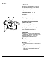
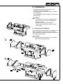
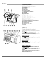
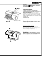
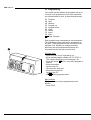
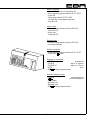
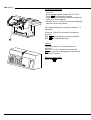
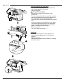
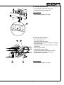
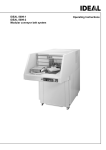
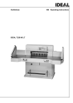
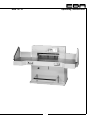
EBA 721 LT
Operating Instructions
-1-
EBA 721 LT
-2-
Table of contents
1. General ........................................................ 4
1.1 Safety Instructions ....................................... 4
1.2 Application ................................................... 4
2. Installation ................................................... 5
2.1 Preparing for Installation .............................. 5
2.2 Power supply ............................................... 6
3.
3.1
3.2
without side tables
3.3
3.4
3.5
Operation .................................................... 7
Checklist ..................................................... 7
Operating elements ..................................... 8
Start-up ........................................................ 8
Display in cm or inch ................................... 8
Manual Foot pedal ....................................... 8
Cutting to a specific size ............................. 8
Calculating .................................................. 9
Cut according to markings .......................... 9
Optical cutting line indicator ........................ 9
Mechanical cutting line indicator .................. 9
Eject function .............................................. 9
Multiple cuts function start ........................... 9
Exiting program-mode ................................. 9
Cutting stop or interruption ........................ 10
Cutting activation ....................................... 10
False clamp plate ...................................... 11
Programming ............................................ 12
Program entry ........................................... 12
Eject function ............................................. 12
Select Program ........................................ 13
Insert a step ............................................... 13
Delete a step ............................................. 13
Delete a program ...................................... 13
Example of a program ............................... 13
How the example works ............................ 13
Working with programs ............................. 14
Exiting program-mode. .............................. 14
4. Maintenance .............................................. 15
4.1 Cutting stick ............................................... 15
Setting the cutting depth ............................ 15
Turning or replacing the cutting stick ......... 16
Cutting test ................................................ 16
4.2 Blade replacement .................................... 17
Removing the blade .................................. 17
Blade mounting ......................................... 18
4.3 Weekly Maintenance ................................. 19
4.4 Monthy Maintenance .................................. 19
Type of grease ........................................... 19
with side tables
-3-
5.
Malfunctions .............................................. 20
6.
Technical data ........................................... 22
7.
Accessories .............................................. 22
EG-declaration of conformity ..................... 23
EBA 721 LT
1. General
This instruction manual will help you to learn the
safe and comfortable operation of this machine.
Please read these operating instructions before
putting the machine into operation and observe the
safety regulations.
1.1 Safety Instructions
Danger!
Non-compliance with the instructions may
endanger persons.
Warning!
Non-compliance with the instructions may
cause damage to the machine.
The operating instructions must always be
available for the operator.
2
01-0
All components which may endanger the operator
are covered by a guard. The casing is connected
(screwed) to the machine.
Operation by one person at a time only.
The cutting action, which is dangerous to the
operator, is protected by a two-handed control
system (22) and safety beam guard (1).
1.2 Application
The machine is designed for cutting stacks of paper
to a specified size. Setting the measurement is done
via buttons or hand wheel (17). Cutting cycle is
activated by a two-handed control system.
Danger!
Only instructed persons are allowed to operate
the machine.
No operation by children.
Danger!
Do not cut any hard material or material liable to
chip.
Danger!
Paper cutting machines are meant exclusively
for the cutting of paper or similar material.
Paper clips or hard material will damage the
cutting blade.
-4-
2. Installation
- Transport the machine on the pallet to its
destination using a pallet-jack.
- 6 strong people are required to lift the machine
from the pallet.
- The machine should be installed on a sturdy, dry
and level floor.
Danger!
- The machine must not be located outside.
- Do not use in the vicinity of inflammable
liquids or gases.
- Do not use in humid environments.
- Protect mains cable against heat, oil and
sharp edges.
2.1 Preparing for Installation
The machine is delivered ready for operation. As an
option, side tables, left and right, are available.
These should be mounted so that the surfaces are
level with the main table.
Danger!
The machine must not be put into operation
without the safety light beam.
-5-
EBA 721 LT
2.2 Power supply
The name plate (23) is located at the rear of the
machine.
- Data stated on the name plate
- Voltage “ V “,
- Frequency “Hz”,
- Power consumption “A”
must correspond to the values of the power supply
unit.
- Connect the machine to the mains.
- Earth wire must be available.
Standard machines are factory-set as follows:
- Voltage 400V (220V) 3 phase
- Frequency 50Hz (60Hz).
Machine does not function
- Switch (5) ON.
- Key-switch (4) ON.
- Check on-site fuse.
- Press the green overload switch (36).
- Press the black overload switch (37).
© If the machine still does not function then the
rotation must be reversed.
3
01-0
The machine is wired according to the IEC
standards. We recommend that alterations to the
rotary direction be made in the socket. It is also
possible to make alterations in the plug by
exchanging „L1“ and „L2“.
Danger!
Incorrect exchanging of the connections will
endanger the operator. This work must be
carried out by an electrician.
-6-
3. Operation
Danger!
The machine may only be operated by trained
persons who have also read and understood
the operating and safety instructions.
Danger!
Check safety devices are complete and
function prior to starting the machine and after
replacing the blade.
Checklist
- Machine panels:
All panels must be mounted
- Cutting activation:
The cutting mechanism starts when the „twohanded control system“ (1) is pressed exactly at
the same time.
- Safety light beam
Do not reach into the cutting area (38) when in
motion.
It is recommended to keep a written copy of the
examination results.
1
04-0
Cutting sequence (1) with automatic clamping:
+
Airtable (9)
The airtable allows paper to be easily positioned.
Setting clamping pressure (7)
1
03-0
The clamp pressure can be adjusted using the
adjustment knob (7).
© The clamping pressure can be read on the light
panel (19).
-7-
EBA 721 LT
3.1 Operating elements
(1)
(2)
(3)
(4)
(5)
(6)
(7)
(8)
(9)
(10)
(11)
(12)
(13)
(14)
(15)
(16)
(17)
(18)
(19)
(20)
(21)
1
01-0
Safety two-handed control system
Backgauge control
Backgauge
Key switch
Main switch
Knocking-up block
Clamp pressure adjustment
Foot pedal
Airtable switch
Program number
Program step
LED „M“ Display Memory
LED „E“ Display Eject
LED „S“ Display Error indication
Display Cutting size
Backgauge, backwards fast
Electronical handwheel for fine adjustment
Backgauge, forwards fast
Clamp pressure
Switch-over cm - inch.
Keypad
3.2 Start-up
- Turn the main switch (5) to position „ I „.
- Insert the key (4) for the control panel and turn to
the right.
key. © Backgauge (3) will
- Press
automatically search for the reference point. The
measurement appears on the display.
Display in cm or inch
M
Prog
ramm
P
Step
S M
C
D
E
I
CP
Stop
Start
© Display changes from cm and inch.
Press
- cm = 4-digit display
- inch = 5-digit display
E
S
7
inch
4
1
0
8
5
2
9
6
3
2000
1750
1500
1250
1000
750
500
250
67-01
Manual Foot pedal
Pre-clamping can be performed using the foot pedal
(8) (e.g. folded stacks).
Cutting to a specific size
- Enter the cut size on the display © the red „S“
(14) light will be on.
key © size is approached, LED „S“ is
- Press
deleted.
- Insert the paper and push it with the knocking-up
block to the backgauge (6).
- Release the cut.
-8-
Calculating:
e.g. 4 8 : 4
© Backgauge advances to
the calculated measurement.
Prog
M
ramm
P S
D
E
Cut according to markings
- Position the backgauge (16) to the back.
- Insert the paper and push it with the knocking-up
block to the backgauge.
- Turn rotary control (17) to the front until the
marking on the paper to be cut is under the light
beam. The more the rotary control is turned the
faster the backgauge will move. For quick motion
use key (18).
- Release the cut.
Step
M
E
S
I
CP
Stop
Start
7
inch
C
4
1
0
8
5
2
9
6
3
2000
1750
1500
1250
1000
750
500
250
Optical cutting line indicator
An optical cutting line indicator is used for exact
cutting. The light beam indicates where the cut will
be made.
2
67-0
Mechanical cutting line indicator
The clamp (24) can be used as cutting line
indicator for exact cutting. Pre-clamping can be
performed using the foot pedal (8).
Eject function
If key E is pressed, tbe backgauge will advance
ejecting the material to be cut, then automatically
return to the position shown in the display.
1
06-0
-9-
EBA 721 LT
Multiple cuts function start
- Enter the cut size on the display.
- Press
key.
- Push the paper to the backgauge.
- Release the cut.
- Press M key © the red „M“ (12) light will be on.
- Enter the constant cut size.
key.
- Press
© the backgauge will advance by the constant cut
size.
67-03
Exiting program-mode
- Press M key © LED „M“ (12) switch OFF, The
actual size is shown.
3.3 Cutting activation
Danger!
Do not reach into the cutting area when the
blade is in motion.
A cut can only be activated when the specified size
is approached. The LED „S“ on the display must be
deleted and the safety area (38) free.
- Press both buttons of the safety two-handed
control system (1) simultaneously and keep them
pressed until the paper is completely cut.
1
04-0
Cutting stop or interruption:
- Release one or both buttons of the two-hand
control (1).
- 10 -
3.4 False clamp plate
A cover plate (39) can be fitted to prevent pressure
marks on sensitive material.
To dismount:
- Remove the clamp plate (39) by pulling it down
- Store the clamp plate in the provided holder (25)
© The remaining cut is 2 cm.
To mount:
- The clamp plate (39) is inserted to the top into the
clamp (24) © The remaining cut is 9 cm
- 11 -
EBA 721 LT
3.5 Programming
The control system enables 20 programs with up to
16 steps to be programmed. One step represents
one measurement or max. 9 chain measurements.
P
S
M
£
¢
C
D
I
E
Program
Step
Memory
Program up
Program down
Clear
Delete
Insert
Eject
Clear Program
Each program step corresponds to one dimension.
The indicated program step can be overwritten at
any time. These programs remain stored when the
machine is off. Should you change to another
dimension unit all programmed measures are
converted into the new unit (cm and inch).
M
Prog
ramm
P
Step
S M
C
D
E
I
CP
Stop
Start
E
S
7
inch
4
1
0
8
5
2
9
6
3
2000
1750
1500
1250
1000
750
500
250
67-04
Program entry:
- Press P © the red „S“ light will be on.
- Enter desired program number 0 1...2 0. ©
The number will be shown in the display (10).
twice © previous program is
- Press the button
deleted.
- Enter the position.
- Confirm with =.
- £ choose the next step.
- Enter the next position
Confirm with =
- P
Exiting program-mode.
Eject function
This function can only be programmed to one
position.
- Press E = .
- 12 -
Select Program
- Press P © the red „S“ light will be on.
- Enter desired program number 0 1...2 0.
- Press S
- Enter step number 0 1...1 6.
- Or enter the next program step with
key £ or ¢.
Insert a step
- Choose a step number with key £ or ¢
- Press key I.
- Enter size.
- Press key =.
Delete a step
- Choose a step number with key £ or ¢
- Press key D twice
Delete a program
- Enter desired program number 0 1...1 6.
twice
- Press key
M
Prog
ramm
P
Step
S M
C
D
E
I
CP
Stop
Start
E
S
7
inch
4
1
0
8
5
2
9
6
3
2000
1750
1500
1250
1000
750
500
250
67
Example of a program
-P08
program 08
step 1 on 19,0cm
-19=
step 2 on 17,0cm
-£17=
eject
-E=
Exiting program-mode.
-P
How the example works
-P08
start program 08
proceed to position
- Insert paper
- Release cut 1
- Release cut 2
Exiting program-mode.
-P
- 13 -
EBA 721 LT
Working with programs
Press P.
Enter desired program number 0 1...1 6.
© proceeds to position.
Press
Insert the paper and push it with the knocking-up
block (6) to the backgauge.
- Release the cut. © After every cut the backgauge
advances to the next position.
-
The cutting mechanism is described under No. 3.
Operation.
Press key ¢ and £ to proceed to the desired
program.
the backgauge proceeds to position.
With
the backgauge stops.
With
General
The red „S“ light is on © specified size not
achieved.
The red „S“ is off © specified size achieved.
key is pressed - Backgauge stops and the
actual size is shown.
M
Prog
ramm
P
Step
S M
C
D
E
I
CP
Stop
Start
E
S
7
inch
4
1
0
8
5
2
9
6
3
Exiting program-mode.
Press P
.
2000
1750
1500
1250
1000
750
500
250
67
- 14 -
4. Maintenance
Danger!
- Maintenance work may only be performed
by trained staff.
- Before replacing the blade or cutting stick
switch off the main switch.
- Disconnect from the mains before
starting any service work or before
removing the cover.
Safety check
According to § 40 VBG 7i a safety check
according to the safety stipulations has to be made
every 5 years by a service team authorised through
our service department. The carrying-out of such a
check has to be attested on the test certificate.
A corresponding test label has to be affixed on the
back of the machine. In Germany such a safety
check is regulated and we recommend it for all
other countries, too.
4.1 Cutting stick
If the last sheet of paper is not completely cut, the
cutting depth must be adjusted.
05-01
Setting the cutting depth
- Lower the blade depth adjustment (27) 1/12 using
a spanner.
- Remove spanner.
- Perform cutting test as described below.
If the cutting stick (26) is very worn it must be
turned.
Warning!
Do not cut into the cutting stick too deep as
this shortens the life time of the blade.
42
498
NID
70
- 15 -
EBA 721 LT
05-02
Turning or replacing the cutting stick
- Turn the blade depth adjustment (27) to the top
until it stops (spanner in tool set).
- Remove spanner.
Danger! Risk of injury!
- Remove the cutting stick (26) with a small
screwdriver.
- Turn the cutting stick (the non-used side must be
near to the blade) and plug it into the holding bolt.
The cutting stick can be used eight times.
- Place the paper onto the whole width of the cutting
area.
- Lower the blade by pressing both cut keys. Keep
one button pressed and turn off the main switch.
- Lower the blade depth adjustment (27) until the
paper is cut along the entire length.
- Remove spanner.
- Turn main switch to position „ I „.
Cutting test
- If the last sheet of paper is not completey cut,
lower the blade adjustment (27) 1/12 using a
spanner.
- Remove spanner.
- Repeat this procedure until the paper is cut along
the entire length.
- 16 -
4.2 Blade replacement
A reduction in the cutting quality indicates that the
blade must be sharpened or a blade change is
necessary.
Danger! Risk of injury!
- The blade is extremely sharp. Do not
remove or transport the blade without
protection.
- Blade replacement work my only be
performed by trained staff.
05-02
.
20
21-02
Removing the blade
- Turn the blade depth adjustment (27) to the top
until it stops (spanner in tool set).
- Remove spanner.
- Lower the blade by pressing both cut buttons.
Keep one button pressed and turn off the main
switch.
- The eccentrics (28) are now exposed and should
be turned to position “0“. The special wrench (40)
found in the tool set.
- Turn main switch to position „ I „.
- Wait until the blade is at ghe top.
- Turn main switch to position „ O „.
- Remove the 2 blade screws (29).
- Put the blade changing tool (31) into place and
fasten it to the blade.
- The remaining screws should then be removed.
- Loosen the grips of the blade changing tool (31)
lightly.
- Allow the blade to be taken downwards out of the
machine.
- Place the blade into the blade carrier and screw it
into place.
23-01
- 17 -
EBA 721 LT
Blade mounting
- Turn resp. replace cutting stick © see „Cutting
stick replacement“.
- Place the blade to be exchanged with the blade
changing tool (31) mounted, into the blade carrier
(30) up to the top and screw it into place with the
grips.
- Lightly tighten 4 of the 6 blade screws (29) (with
washers).
- Remove the blade changing tool.
- Lightly tighten the remaining blade screws (with
washers) (2).
- Remove all tools and position a sheet of paper
along the entire cutting length.
- Lower the blade by pressing both cut buttons.
Keep one button pressed and turn off the main
switch.
- Lower the blade depth adjustment (27) until the
blade touches the paper.
- The 3 eccentrics (28) should then be used to
lower the blade until the paper is cut along the
entire length of the blade © (The blade must
remain parallel to the cutting stick).
- Turn main switch to position „ I „.
- The blade will return to the upper position and the
blade screws should be tightened firmly.
- Cut a stack of paper to test.
Warning!
05-02
Blades may only be sharpened by a specialist.
21-02
- 18 -
4.3 Weekly Maintenance
- The backgauge should be advanced.
- Lubricate the grease nipple (32).
Type of grease
- Roller bearing grease - all types.
4.4 Monthy Maintenance
- Turn main switch off.
- Disconnect from the mains.
- Remove the front upper housing (43) © taking
care of the cable.
- Check oil (34). If oil is below minimum contact
your dealer.
- Remove paper debris.
- Lubricate all grease nipples.
- Check the joint bolts (35) if they are worn.
- Check connecting rod (33) if it is worn.
- Reassemble the machine.
Type of grease
- Roller bearing grease - all types.
- 19 -
EBA 721 LT
5. Malfunctions
Danger!
Disconnect from the mains before starting
any service work or before removing the
cover.
Malfunction:
No display.
Cause:
Power supply.
Remedy:
- Plug in to the mains.
- Mains switch on.
- Check on-site fuse.
- Overload switch green (36) pressed.
Malfunction:
Optical cutting line indicator does not function after
the machine has been moved to another position.
Cause:
Phase direction wrong.
Remedy:
See „Installation and, Power supply“.
Malfunction:
Backgauge does not function.
Cause:
Motor is overloaded.
Remedy:
Press safety switch (37).
Malfunction:
Cut cannot be activated.
a) Cause:
Safety light beam is interrupted / dirty?
Remedy:
Remove any items and clean the sender.
b) Cause:
Backgauge does not go to the correct position.
© the red „S“ light is on.
Remedy:
again.
Press
c) Cause:
Size under 9 cm.
Remedy:
Put the false clamp in the provided holder.
- 20 -
Malfunction:
Machine is switched on but cut cannot be
performed.
Cause:
Safety clutch is activated.
Remedy:
Contact your dealer.
Malfunction:
The last sheet of paper is not completely cut.
Remedy:
Adjust the cutting depth (see Cutting stick) or
replace or turn the cutting stick.
Malfunction:
Poor cutting quality or blade jams.
Remedy:
Blade change or adjustment is necessary.
Malfunction:
No clamp pressure
Cause:
Hydraulic oil needs refilling
Remedy:
Contact your dealer.
If you have further questions please contact your
dealer or directly on the internet [email protected]
Subject to alteration wihout notice
- 21 -
EBA 721 LT
6. Technical data
Sound level DIN 45635-27:
max. 73 dB(A)
Minimum space requirement B x T:
without side tables
130 cm x 151 cm
with side tables
210 cm x 160 cm
Clamping pressure
250 dN bis 2000 dN
Weight without side tables:
584 kg
Weight with side tables:
620 kg
Capacity of hydraulic oil
Shell Tellus C32 or similar
1,5 l
Used oil must be disposed of at the
authorized place.
The exact technical specifications can be found on
the technical specifications sticker on the machine.
Safety light beam
Total reaction time of safety device:
Resolution top
20
Resolution front
Distance:
238
Distance:
318
Distance:
460
95 ms
mm; 30 mm
40 mm
mm; 20 mm
mm; 30 mm
mm; 40 mm
7. Accessories
Attention!
Only use accessories recommended by the
manufacturer.
Not all of the accessories illustrated or
described are included as standard delivery.
16
Knocking-up block (6)
9000 521
Blade change set (31)
9000 514
HSS - Blade (42)
6 Cutting sticks (26)
Side tables left and right
9000 141
9000 039
9000 550
Grease gun (44)
9004 683
27
- 22 -
EG-KONFORMITÄTSERKLÄRUNG
EC-declaration of conformity
Déclaration de conformité CE
Declaración CE de conformidad
Dichiarazione CE di conformità
EG-verklaring van overeenstemming
Declaraçao CE de conformidade
EF-overensstemmelseserklæring
- Hiermit erklären wir, daß die Bauart von
- Herewith we declare that
- Par la présente, nous déclarons que
- Por la presente, declaramos que la
- Si dichiara che il modello della
- Hiermede verklaren wij, dat de in de handel gebrachte machine
- Com a presente, declaramos que o modelo da
- Hermed erklæres, at produkttypen
721;
721 LT
- folgenden einschlägigen Bestimmungen entspricht:
- complies with the following provisons applying to it:
- sont conformes aux dispositions pertinentes suivantes:
- satisface las disposiciones pertinentes siguientes:
- è conforme alle seguenti disposizioni pertinenti:
- voldoet aan de eisen van de in het vervolg genoemde bepalingen:
- está em conformidade com as disposições pertinentes, a saber:
- er i overensstemmelse med følgende bestemmelser:
EG98-37;
EG73/23;
EG89/336
- Angewendete harmonisierte Normen insbesondere
- Applied harmonized standards in particular
- Normes harmonisée utilisées, notamment
- Normas armonizadas utilizadas particularmente
- Norme armonizzate applicate in particolare
- Gebruikte geharmoniseerde normen, in het bijzondere
- Normas harmonizadas utilizadas, em particular
- Harmoniserede standarder, der blev anvendt, i særdaleshed
EN60204; prEN1010-1; prEN1010-3; EN55014-1; EN55014-2;
EN61000-3-2; EN61000-3-3; prEN50100-1; prEN50100-2;
EN292; EN294 EN27779; EN349; DIN45635-27
Krug & Priester GmbH u. Co KG
72336 Balingen, Germany
28. 8. 2002
Datum
- 23 -
Wolfgang Priester
- General Manager -
B_721_2h.PMD 09/2002
EBA 721 LT
EBA Krug & Priester
72336 Balingen
- 24 -
Germany
www.eba.de