1
Drive Technology \ Drive Automation \ System Integration \ Services
Operating Instructions
Explosion-Proof AC Motors EDR.71 – 225
Edition 06/2011
17076013 / EN
SEW-EURODRIVE—Driving the world
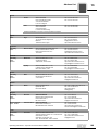
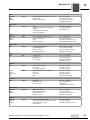
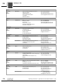
Contents
Contents
1
2
3
4
General Information ............................................................................................ 6
1.1
How to use this documentation ................................................................... 6
1.2
Structure of the safety notes ....................................................................... 6
1.3
Rights to claim under warranty ................................................................... 7
1.4
Exclusion of liability..................................................................................... 7
1.5
Copyright..................................................................................................... 7
1.6
Product name and trademarks.................................................................... 7
Safety Notes ........................................................................................................ 8
2.1
Preliminary information ............................................................................... 8
2.2
General information .................................................................................... 8
2.3
Target group ............................................................................................... 9
2.4
Designated use ........................................................................................... 9
2.5
Other applicable documentation ............................................................... 10
2.6
Transport/storage...................................................................................... 10
2.7
Installation ................................................................................................ 10
2.8
Electrical connection ................................................................................. 11
2.9
Startup/operation ...................................................................................... 11
Motor Structure ................................................................................................. 12
3.1
General structure of EDR.71 – EDR.132 .................................................. 13
3.2
General structure EDR.160 – EDR.180 .................................................... 14
3.3
General structure EDR.200 – EDR.225 .................................................... 15
3.4
Nameplate, type designation .................................................................... 16
3.5
Additional features .................................................................................... 18
3.6
Explosion protection designations ............................................................ 20
Mechanical Installation..................................................................................... 22
4.1
Before you start......................................................................................... 22
4.2
Long-term storage of motors..................................................................... 23
4.3
Motor installation notes ............................................................................. 25
4.4
Mounting tolerances.................................................................................. 27
4.5
Assembling the input elements ................................................................. 27
4.6
Non-SEW encoder mounting .................................................................... 27
4.7
Connecting XV.A encoder mounting adapter to EDR.71 – 225 motors .... 28
4.8
Turning the terminal box ........................................................................... 30
4.9
Coating...................................................................................................... 34
4.10 Additional features .................................................................................... 34
5
Electrical Installation ........................................................................................ 37
5.1
Additional regulations................................................................................ 37
5.2
Wiring diagrams and terminal assignment diagrams ................................ 37
5.3
Cable entries............................................................................................. 37
5.4
Equipotential bonding ............................................................................... 38
5.5
Wiring notes .............................................................................................. 38
5.6
Special aspects for operation with a frequency inverter ........................... 39
5.7
Improving the grounding (EMC) ................................................................ 39
Operating Instructions – Explosion-Proof AC Motors EDR.71 – 225
3
Contents
5.8
Special aspects in switching operation ..................................................... 42
5.9
Ambient conditions during operation......................................................... 43
5.10 Motors of categories 2GD and 3GD.......................................................... 44
5.11 Notes on motor connection ....................................................................... 47
5.12 Motor connection via terminal board ......................................................... 48
5.13 Connecting the motor via terminal strip .................................................... 51
5.14 Connecting the brake ................................................................................ 52
5.15 Accessory equipment................................................................................ 53
6
7
8
9
Operating Modes and Limit Values ................................................................. 59
6.1
Permitted duty types ................................................................................. 59
6.2
Use............................................................................................................ 61
6.3
Safe operation of motors of category 2 ..................................................... 62
6.4
Safe operation of motors of category 3 ..................................................... 65
6.5
Typical application .................................................................................... 69
6.6
Special application .................................................................................... 71
Startup................................................................................................................ 81
7.1
Before startup ........................................................................................... 82
7.2
During startup ........................................................................................... 82
7.3
Parameter setting: Frequency inverters for category 2GD motors ........... 83
7.4
Parameter setting: Frequency inverters for category 3 motors ................. 88
7.5
Changing the blocking direction of motors with backstop ......................... 90
Inspection/Maintenance ................................................................................... 93
8.1
Inspection and maintenance intervals....................................................... 95
8.2
Bearing lubrication .................................................................................... 95
8.3
Corrosion protection.................................................................................. 95
8.4
Motor and brake maintenance – preliminary work .................................... 96
8.5
Inspection/maintenance for EDR.71 – EDR.225 motors......................... 102
8.6
Inspection/maintenance for EDR.71 – EDR.225 brakemotors................ 107
Technical Data ................................................................................................ 126
9.1
Overhung loads....................................................................................... 126
9.2
Braking torque assignment ..................................................................... 134
9.3
Work done, working air gap, braking torques ........................................ 135
9.4
Operating currents .................................................................................. 136
9.5
Resistors ................................................................................................. 138
9.6
Brake control........................................................................................... 140
9.7
Permitted work done by the BE brake for AC motors ............................. 141
9.8
Permitted rolling bearing types ............................................................... 145
9.9
Lubricant tables....................................................................................... 146
9.10 Order information for lubricants and anti-corrosion agents ..................... 146
9.11 Encoders................................................................................................. 147
9.12 Nameplate marking ................................................................................. 150
4
Operating Instructions – Explosion-Proof AC Motors EDR.71 – 225
Contents
10
Malfunctions .................................................................................................... 151
10.1 Motor malfunctions.................................................................................. 152
10.2 Brake malfunctions ................................................................................ 154
10.3 Malfunctions when operated with a frequency inverter ........................... 155
10.4 Disposal .................................................................................................. 155
10.5 Customer service .................................................................................... 155
11
Appendix.......................................................................................................... 156
11.1 Wiring diagrams ...................................................................................... 156
11.2 Encoders ES7. /AS7. /EG7. /AG7........................................................... 158
11.3 Terminal strips 1 and 2 ........................................................................... 159
11.4 Forced cooling fan VE............................................................................. 160
11.5 Operating and maintenance instructions for WISTRO forced cooling fans...
162
12
Declarations of Conformity ............................................................................ 164
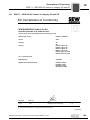
12.1 EDR.71 – EDR.225 AC motors in category 2G and 2D .......................... 165
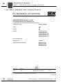
12.2 EDR.71 – EDR.225 AC motors in category 3G and 3D .......................... 166
12.3 VE forced cooling fan .............................................................................. 167
13
Address List .................................................................................................... 168
Index................................................................................................................. 179
Operating Instructions – Explosion-Proof AC Motors EDR.71 – 225
5
General Information
How to use this documentation
1
1
General Information
1.1
How to use this documentation
The documentation is an integral part of the product and contains important information
on operation and service. The documentation is written for all employees who assemble,
install, startup, and service this product.
The documentation must be accessible and legible. Make sure that persons responsible
for the system and its operation, as well as persons who work independently on the unit,
have read through the documentation carefully and understood it. If you are unclear
about any of the information in this documentation, or if you require further information,
contact SEW-EURODRIVE.
1.2
Structure of the safety notes
1.2.1
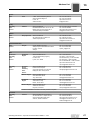
Meaning of the signal words
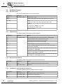
The following table shows the grading and meaning of the signal words for safety notes,
notes on potential risks of damage to property, and other notes.
Signal word
1.2.2
Meaning
Consequences if disregarded
DANGER
Imminent danger
Severe or fatal injuries
WARNING
Possible dangerous situation
Severe or fatal injuries
CAUTION
Possible dangerous situation
Minor injuries
NOTICE
Possible damage to property
Damage to the drive system or its
environment
NOTE ON
EXPLOSION
PROTECTION
Important note on explosion
protection
Suspension of explosion protection and
resulting hazards
INFORMATION
Useful information or tip: Simplifies the handling of the drive
system.
Structure of the section-related safety notes
Section safety notes do not apply to a specific action, but to several actions pertaining
to one subject. The used symbols indicate either a general or a specific hazard.
This is the formal structure of a section safety note:
SIGNAL WORD
Type and source of danger.
Possible consequence(s) if disregarded.
•
1.2.3
Measure(s) to prevent the danger.
Structure of the embedded safety notes
Embedded safety notes are directly integrated in the instructions just before the description of the dangerous action.
This is the formal structure of an embedded safety note:
•
SIGNAL WORD Nature and source of hazard.
Possible consequence(s) if disregarded.
– Measure(s) to prevent the danger.
6
Operating Instructions – Explosion-Proof AC Motors EDR.71 – 225
General Information
Rights to claim under warranty
1.3
1
Rights to claim under warranty
A requirement of fault-free operation and fulfillment of any rights to claim under limited
warranty is that you adhere to the information in the documentation. Read the documentation before you start working with the unit!
1.4
Exclusion of liability
You must comply with the information contained in this documentation to ensure safe
operation of the EDR.. series AC motors units and to achieve the specified product characteristics and performance requirements. SEW-EURODRIVE assumes no liability for
injury to persons or damage to equipment or property resulting from non-observance of
the documentation. In such cases, any liability for defects is excluded.
1.5
Copyright
© 2011 - SEW-EURODRIVE. All rights reserved.
Copyright law prohibits the unauthorized duplication, modification, distribution, and use
of this document, in whole or in part.
1.6
Product name and trademarks
The brands and product names contained within this publication are trademarks or registered trademarks of the titleholders.
Operating Instructions – Explosion-Proof AC Motors EDR.71 – 225
7
Safety Notes
Preliminary information
2
2
Safety Notes
The following basic safety notes must be read carefully to prevent injury to persons and
damage to property. The operator must ensure that the basic safety notes are read and
adhered to. Make sure that persons responsible for the system and its operation, as well
as persons who work independently on the unit, have read through the operating instructions carefully and understood them. If you are unclear about any of the information in
this documentation or if you require further information, please contact SEWEURODRIVE.
2.1
Preliminary information
The following safety notes are primarily concerned with the use of the following components: EDR.. series AC motors. If using gearmotors, please also refer to the safety notes
in the corresponding operating instructions for:
•
Gear unit
Also observe the supplementary safety notes in the individual sections of this documentation.
2.2
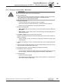
General information
WARNING
During operation, the motors and gearmotors can have live, bare (in the event of open
connectors/terminal boxes) and movable or rotating parts as well as hot surfaces,
depending on their enclosure.
Severe or fatal injuries.
•
•
•
All work related to transportation, storage, installation, assembly, connection,
startup, maintenance and repair may only be carried out by qualified personnel, in
strict observance of:
– The relevant detailed operating instructions
– The warning and safety signs on the motor/gearmotor
– All other project planning documents, operating instructions and wiring
diagrams related to the drive
– The specific regulations and requirements for the system
– The national/regional regulations governing safety and the prevention of accidents
Never install damaged products
Immediately report any damage to the shipping company
Removing the required protection cover or the housing without authorization, improper
use as well as incorrect installation or operation may result in severe injuries to persons
or damage to property.
This documentation provides additional information.
8
Operating Instructions – Explosion-Proof AC Motors EDR.71 – 225
Safety Notes
Target group
2.3
2
Target group
Any mechanical work may only be performed by adequately qualified personnel. Qualified staff in the context of this documentation are persons familiar with the design,
mechanical installation, troubleshooting and servicing of the product who possess the
following qualifications:
•
Training in mechanical engineering, e.g. as a mechanic or mechatronics technician
(final examinations must have been passed).
•
They are familiar with these operating instructions.
Any electronic work may only be performed by adequately qualified electricians. Qualified electricians in the context of this documentation are persons familiar with electrical
installation, startup, troubleshooting and servicing of the product who possess the
following qualifications:
•
Training in electrical engineering, e.g. as an electrician, electronics or mechatronics
technician (final examinations must have been passed).
•
They are familiar with these operating instructions.
All work in further areas of transportation, storage, operation and waste disposal must
only be carried out by persons who are trained appropriately.
All qualified personnel must wear appropriate protective clothing.
2.4
Designated use
The explosion-proof electric motors are intended for industrial systems.
When installed in machines, startup of the motors (i.e. start of designated operation) is
prohibited until it is determined that the machine meets the requirements stipulated in
EC Directive 94/9/EC (ATEX Directive).
NOTES ON EXPLOSION PROTECTION
•
•
•
•
The motor is only allowed to be operated under the conditions described in the
"Startup" section.
A motor may only be operated with the frequency inverter when the requirements
of the prototype test certificates and/or this documentation and the information on
the nameplate of the motor, if available, are fulfilled.
There may be no aggressive substances in the vicinity that could damage the paint
and seals.
The motors must not be operated in areas/applications that cause strong electrical
charge on the motor housing, e.g. as a fan motor in a dust-transporting tube as this
may cause electrostatic charge of the coated surfaces.
Air-cooled types are dimensioned for ambient temperatures of -20 °C to +40 °C and installation altitudes ≤ 1000 m above sea level. Note that information on the nameplate
may differ. The ambient conditions must comply with all the specifications on the nameplate.
Operating Instructions – Explosion-Proof AC Motors EDR.71 – 225
9
Safety Notes
Other applicable documentation
2
2.5
Other applicable documentation
The following publications and documents have to be observed as well:
2.6
•
Wiring diagrams provided with the motor
•
Operating instructions "Explosion-Proof Gear Units R..7, F..7, K..7, S..7 Series,
SPIROPLAN® W" for gearmotors
•
Operating instructions of any mounted frequency inverter for motors powered by
inverters.
•
Operating instructions of installed options, if applicable
•
"DR Series AC Motors" catalog and/or
•
"DR Gearmotors" catalog
•
"Explosion-Proof AC Motors" catalog and/or
•
"Explosion-proof drives" catalog
Transport/storage
Inspect the shipment for any damage that may have occurred in transit as soon as you
receive the delivery. Inform the shipping company immediately. It may be necessary to
preclude startup.
Tighten the eyebolts securely. They are designed to only carry the weight of the motor/
gearmotor; do not attach any additional loads.
The built-in lifting eyebolts comply with DIN 580. Always observe the loads and regulations listed in this standard. If the gearmotor is equipped with two eyebolts, then both of
these should be used for transportation. In this case, the tension force vector of the
slings must not exceed a 45° angle according to DIN 580.
Use suitable, sufficiently rated handling equipment if required. Reattach these in the
case of further transportation.
Store the motor/gearmotor in a dry, dust-free environment if it is not to be installed
straight away. You must not store the motor/gearmotor outdoors or on the fan guard.
The motor/gearmotor can be stored for one year without requiring any special measures
before startup.
2.7
Installation
Make sure that the supports are even, the foot and flange mounting is correct and if
there is direct coupling, align with precision. Resonances between the rotational
frequency and the double network frequency caused by the structure are to be avoided.
Release the brake (if installed), turn rotor manually, check for unusual grinding noise.
Check the direction of rotation in decoupled status.
Only install or remove belt pulleys and couplings using suitable devices (heat up) and
cover with a touch guard. Avoid improper belt tension.
Make the pipe connections that may eventually be required. Mounting positions with
shaft ends pointing upwards should be equipped with a cover to prevent foreign objects
from falling into the fan. Ensure that ventilation openings are not obstructed and that
used air, including air from adjacent units, cannot be drawn in again straight away.
Observe the notes in the "Mechanical Installation" chapter.
10
Operating Instructions – Explosion-Proof AC Motors EDR.71 – 225
Safety Notes
Electrical connection
2.8
2
Electrical connection
All work may only be carried out by qualified personnel. During work, the low-voltage
machine must be on standstill, enabled, and safeguarded against an accidental restart.
This also applies to auxiliary circuits (e.g. anti-condensation heating or forced cooling
fan).
Check that the motor is de-energized!
Exceeding the tolerances in EN 60034-1 (VDE 0530, part 1) – voltage +5 %, frequency
+2 %, curve shape, symmetry – increases the heating and influences electromagnetic
compatibility. Also observe DIN IEC 60364 and EN 50110 (and, if applicable, other national regulations, such as DIN VDE 0105 for Germany).
In addition to the generally applicable installation regulations for low-voltage equipment,
it is also necessary to comply with the special regulations for setting up electrical machinery in potentially explosive atmospheres (operating safety regulations in Germany:
EN 60079-14; EN 61241-14 and system-specific regulations).
Observe the wiring information and differing data on the nameplate as well as the wiring
diagram in the terminal box.
The connection should be a continuous secure electrical connection (no protruding wire
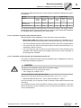
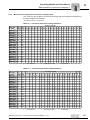
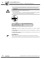
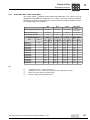
ends); use the cable end equipment intended for this purpose. Establish a secure protective earth connection. When the motor is connected, the distances between live and
conductive parts must not be shorter than the minimum values according to DIN EN /
IEC 60079-7 and -15 and national regulations. The minimum values according to the
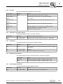
respective standards must be observed, see the following table:
Nominal voltage VN
Distance for motors in category
3
(DIN EN / IEC 60079-15)
Distance for motors in category
2
(DIN EN / IEC 60079-7)
≤ 500 V
5 mm
8 mm
> 500 V to ≤ 690 V
5.5 mm
10 mm
The terminal box must be free of foreign objects, dirt and humidity. Unused cable entry
openings and the box itself must be closed so that they are dust and water proof. Secure
keys for test mode without output elements. Assure yourself of the flawless operability
prior to starting up low-voltage machines.
Observe the notes in the "Electrical Installation" chapter.
2.9
Startup/operation
Whenever changes to normal operation occur, such as increased temperatures, noise,
vibrations, etc., you should determine the cause. Consult the manufacturer if required.
Never deactivate protection devices, even in test mode. Switch off the motor if you are
not sure.
Regularly clean air ducts in dusty or dirty environments.
Operating Instructions – Explosion-Proof AC Motors EDR.71 – 225
11
Motor Structure
3
3
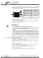
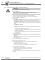
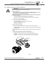
Motor Structure
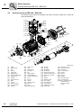
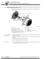
INFORMATION
The following illustration is intended to explain the general structure. It helps you to
assign components to the spare parts list. Deviations are possible depending on the
motor size and version.
12
Operating Instructions – Explosion-Proof AC Motors EDR.71 – 225
Motor Structure
General structure of EDR.71 – EDR.132
3.1
3
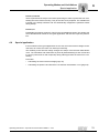
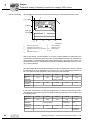
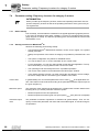
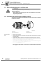
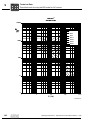
General structure of EDR.71 – EDR.132
The following figure shows an example of the basic structure of EDR.71 – EDR.132 with
spring terminal strip:
[132]
[123]
[117]
[131]
[124]
[118]
[262]
[616]
[137]
[148]
[128]
[140]
[139]
[129] [134]
[116]
[119]
[122]
[112]
[111]
[707]
[716]
[452]
[705]
[715] [706]
[113]
[454]
[13]
[30]
[35]
[42]
[9]
[36]
[12]
[32]
[16] [41] [22]
[44]
[24]
[108]
[106]
[109]
[107]
[90]
[3]
[11]
[100]
[7] [103]
[1]
[93]
[10]
[2]
[1]
[2]
[3]
[7]
[9]
[10]
[11]
[12]
[13]
[16]
[22]
[24]
[30]
[32]
Rotor
Retaining ring
Key
Flanged endshield
Screw plug
Retaining ring
Grooved ball bearing
Retaining ring
Machine screw
Stator
Hex head screw
Eyebolt
Oil seal
Retaining ring
[35]
[36]
[41]
[42]
[44]
[90]
[93]
[100]
[103]
[106]
[107]
[108]
[109]
[111]
Fan guard
Fan
Shim
B-side endshield
Grooved ball bearing
Base plate
Countersunk screw
Hex nut
Stud
Oil seal
Oil flinger
Nameplate
Grooved pin
Gasket for lower part
[112]
[113]
[116]
[117]
[118]
[119]
[122]
[123]
[124]
[128]
[129]
[131]
[132]
[134]
Terminal box lower part
Pan head screw
Terminal clip
Hex head screw
Lock washer
Pan head screw
Lock washer
Hex head screw
Lock washer
Terminal clip
Screw plug
Gasket for cover
Terminal box cover
Screw plug
Operating Instructions – Explosion-Proof AC Motors EDR.71 – 225
[137]
[139]
[140]
[148]
[262]
[392]
[452]
[454]
[616]
[705]
[706]
[707]
[715]
[716]
2931885963
Screw
Hex head screw
Lock washer
Terminal clip
Terminal
Seal
Terminal strip
Support rail
Retaining plate
Canopy
Spacers
Pan head screw
Blind rivet
Washer
13
Motor Structure
General structure EDR.160 – EDR.180
3
3.2
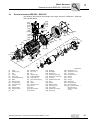
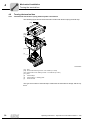
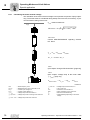
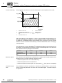
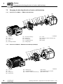
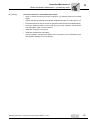
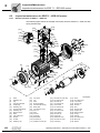
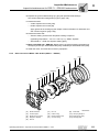
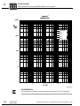
General structure EDR.160 – EDR.180
The following figure shows an example of the basic structure of EDR.160 – EDR.180
with anti-twist frame:
[123]
[219]
[118]
[116]
[117]
[124]
[132]
[131 ]
[262]
[616]
[137]
[119]
[122]
[1213]
[128]
[140]
[134]
[129 ]
[112]
[139]
[707]
[706]
[111]
[715]
[16]
[9]
[30]
[705]
[30]
[19]
[12]
[17]
[22]
[109]
[108]
[7]
[106]
[36]
[42]
[41]
[32]
[44]
[31]
[24]
[107]
[93]
[94]
[1]
[15]
[100]
[90]
[3]
[14]
[11]
[103]
[104]
[10]
[2]
[1]
[2]
[3]
[7]
[9]
[10]
[11]
[12]
[14]
[15]
[16]
[17]
[19]
[22]
[24]
14
Rotor
Retaining ring
Key
Flange
Screw plug
Retaining ring
Grooved ball bearing
Retaining ring
Washer
Hex head screw
Stator
Hex nut
Machine screw
Hex head screw
Eyebolt
[30]
[31]
[32]
[35]
[36]
[41]
[42]
[44]
[90]
[91]
[93]
[94]
[100]
[103]
[104]
Sealing ring
Key
Retaining ring
Fan guard
Fan
Spring washer
B-side endshield
Grooved ball bearing
Foot
Hex nut
Washer
Machine screw
Hex nut
Stud
Supporting ring
[106]
[107]
[108]
[109]
[111]
[112]
[116]
[117]
[118]
[119]
[122]
[123]
[124]
[128]
[129]
Oil seal
Oil flinger
Nameplate
Grooved pin
Gasket for lower part
Terminal box lower part
Serrated lock washer
Stud
Washer
Machine screw
Lock washer
Hex head screw
Lock washer
Serrated lock washer
Screw plug
2967197579
[131] Gasket for cover
[132] Terminal box cover
[134] Screw plug
[139] Hex head screw
[140] Washer
[219] Hex nut
[705] Canopy
[706] Spacers
[707] Hex head screw
[715] Hex head screw
[1213] Kit (1 anti-twist frame, 1
terminal board, 4
sleeves, 2 screws,
2 nuts)
Operating Instructions – Explosion-Proof AC Motors EDR.71 – 225
Motor Structure
General structure EDR.200 – EDR.225
3.3
3
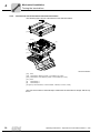
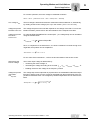
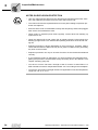
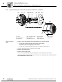
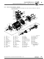
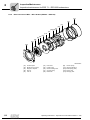
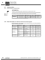
General structure EDR.200 – EDR.225
The following figure shows an example of the basic structure of EDR.200 – EDR.225
with anti-twist frame:
[219]
[118]
[116]
[117]
[123]
[124]
[132]
[131 ]
[119]
[122]
[1213]
[128] [140]
[139]
[707]
[705]
[112]
[111]
[129]
[109]
[706]
[134]
[715]
[108]
[30]
[16]
[9]
[26]
[36] [32]
[35]
[25]
[40]
[19]
[105]
[44]
[43]
[21]
[42] [22]
[31]
[106]
[107]
[24]
[103]
[100]
[3]
[90]
[93]
[1]
[11]
[93]
[2]
[1]
[2]
[3]
[7]
[9]
[11]
[16]
[19]
[21]
[22]
[24]
[25]
[26]
[31]
Rotor
Retaining ring
Key
Flange
Screw plug
Grooved ball bearing
Stator
Machine screw
Oil seal flange
Hex head screw
Eyebolt
Machine screw
Sealing washer
Key
[32]
[35]
[36]
[40]
[42]
[43]
[44]
[90]
[93]
[94]
[100]
[103]
[105]
[106]
Retaining ring
Fan guard
Fan
Retaining ring
B-side endshield
Supporting ring
Grooved ball bearing
Foot
Washer
Machine screw
Hex nut
Stud
Spring washer
Oil seal
[107]
[108]
[109]
[111]
[112]
[107]
[116]
[117]
[118]
[119]
[123]
[124]
[128]
[129]
Operating Instructions – Explosion-Proof AC Motors EDR.71 – 225
Oil flinger
Nameplate
Grooved pin
Gasket for lower part
Terminal box lower part
Oil flinger
Serrated lock washer
Stud
Washer
Machine screw
Hex head screw
Lock washer
Serrated lock washer
Screw plug
[131]
[132]
[134]
[139]
[140]
[219]
[705]
[706]
[707]
[715]
[1213]
3055268107
Gasket for cover
Terminal box cover
Screw plug
Hex head screw
Washer
Hex nut
Canopy
Spacer bolt
Hex head screw
Hex head screw
Kit (1 anti-twist frame, 1
terminal board, 4
sleeves, 2 screws,
2 nuts)
15
Motor Structure
Nameplate, type designation
3
3.4
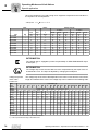
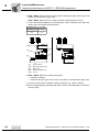
Nameplate, type designation
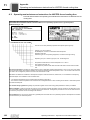
3.4.1
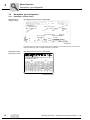
Nameplates of EDR. motors
EDRE motor in
category 2GD
The following figure shows a nameplate:
6306-2Z-J-C3
6205-2Z-J-C3
EDRE90M4/2GD
0102
PTB 10 ATEX 1234 / 01
01.1151928301.0001.09
1430
50
220-240
1,5
82,5
/ 380-420Y
II2D Ex tb IIIC T120°C Db
Kundenartikel-Nr.
65
19
16
86,4
PTB 10 ATEX 1234 / 02
II2G Ex e IICT3 Gb
B3
6,9
0,77
3,48
13A47B911
155 (F)
130 (B)
-20..+40
2010
2439213579
The marks (see page 150) on the upper edge of the nameplate are only present when the motor has been
certified accordingly or when it includes the relevant components.
EDRE motor with
frequency inverter
The following figure shows a nameplate:
R77/II2GD EDRE90L4/3GD/KCC/TF/AL
01.1700099511.0001.11
1435
0188 592 8.12
9.4
9007202350032139
16
Operating Instructions – Explosion-Proof AC Motors EDR.71 – 225
Motor Structure
Nameplate, type designation
3.4.2
3
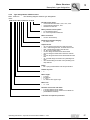
Type designations of EDR. motors
EDR.. series AC
motor
The following diagram shows a type designation:
E DRE 90 M 4 /BE2 /FI /2GD /KCC /TF /ES7S
Encoder motor option:
• Incremental encoders ES7., EG7., AS7., AG7.
• Incremental encoder EV2., EV7.
• Absolute encoder AV7.
Motor protection motor option:
• TF temperature sensor
• PT or KY temperature detection
Motor connection:
• via KCC terminal strip
Explosion protection category:
• 2G, 2GD or 3GD
Output variant:
• /FF: IEC flange-mounted motor with bore holes
• /FG: 7 Series integral motor, as stand-alone motor
• /FM: 7 Series integral motor with IEC feet
• /FI: IEC foot-mounted motor
• /FT: IEC flange-mounted motor with threads
• /FE: IEC flange-mounted motor with bore and IEC
feet
• /FY: IEC flange-mounted motor with threads and IEC
feet
• /FL: General flange-mounted motor (deviating from
IEC)
• /FK: General flange-mounted motor (deviating from
IEC) with feet
Brake:
• BE.. spring-loaded brakes with size specification
Number of poles:
• 4
Motor length:
• S: Short
• M: Medium
• L: Long
• LC: Rotors with copper cage
Motor size:
• 71 – 225
DR motor series with code letter:
• S: Energy-efficient motor variant
• E: Energy-efficient motor variant IE2 or MEPS AS
(Australia/New Zealand)
Code letter for explosion protection
Operating Instructions – Explosion-Proof AC Motors EDR.71 – 225
17
Motor Structure
Additional features
3
3.5
Additional features
3.5.1
AC motor series
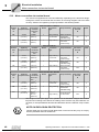
The following table shows the AC motor variants:
Designation
Category
EDRS..
/2G, /2GD, /3GD
ATEX motor, 50 Hz
EDRE..
ATEX energy-efficient motor, High Efficiency IE2, 50 Hz
71 – 225
Sizes:
71 / 80 / 90 / 100 / 112 / 132 / 160 / 180 / 200 / 225
S–L
Lengths:
S = Short / M = Medium / L = Long
LC = Rotors with copper cage
4
3.5.2
Number of poles
Output variants
The following table shows possible output variants:
Designation
Category
Option
/FI
/2G, /2GD, /3GD
IEC foot-mounted motor with specification of shaft height
/FG
7 Series integral motor, as stand-alone motor
/FF
IEC flange-mounted motor with bore holes
/FT
IEC flange-mounted motor with threads
/FL
General flange-mounted motor (other than IEC)
/FM
7 series integral gearmotor with IEC feet, with specification of
shaft height if required
/FE
IEC flange-mounted motor with bore holes and IEC feet, with
specification of shaft height
/FY
IEC flange-mounted motor with thread and IEC feet, with specification of shaft height if required
/FK
General flange-mounted motor (other than IEC) with feet, with
specification of shaft height if required
3.5.3
Mechanical attachments
The following table shows possible mechanical attachments:
Designation
Category
Option
/BE
/3GD
Spring-loaded brake with specification of size
/RS
/2G, /2GD, /3GD
Backstop
3.5.4
Temperature sensor/temperature detection
The following table shows the thermal protection options:
18
Designation
Category
Option
/TF
/2G, /2GD, /3GD
Temperature sensor (PTC resistors)
/KY
/2G, /2GD, /3GD
One KTY84 – 130 sensor
/PT
/2G, /2GD, /3GD
One / three PT100 sensor(s)
Operating Instructions – Explosion-Proof AC Motors EDR.71 – 225
Motor Structure
Additional features
3.5.5
3
Encoder
The following table shows possible encoder variants:
Designation
Category
Option
/ES7S /EG7S /EV7S /3GD
Mounted speed sensor with sin/cos interface
/ES7R/ EG7R
Mounted speed sensor with TTL (RS-422) interface,
/EV7R
V = 9 – 26 V
/AS7W /AG7W
Mounted absolute encoder, RS-485 interface (multi-turn)
/AV7W
/AS7Y /AG7Y /AV2Y
/AV7Y
Mounted absolute encoder, SSI interface (multi-turn)
/ES7A/EG7A
Mounting adapter for encoders from the SEW portfolio
/XV.A
Mounting adapter for non-SEW encoders
/XV..
Mounted non-SEW encoders
3.5.6
Alternative connection options
The following table shows the connection variants:
Designation
Category
Included in the scope of delivery
/KCC
/2G, /2GD, /3GD
Terminal strip with cage clamps (for EDR.71 – EDR.132)
3.5.7
Ventilation
The following table shows possible ventilation variants:
Designation
Category
Option
/VE
/3GD
Forced cooling fan for motors according to 94/9/EC, category 3
(gas / dust)
/AL
/2G, /2GD, /3GD
Metal fan
/C
/2G, /2GD, /3GD
Protection canopy for the fan guard
3.5.8
Explosion-proof motors
The following table shows the possible explosion protection categories:
3.5.9
Designation
Option
/2G, /2GD
Motors according to 94/9/EC, category 2 (gas / dust)
/3GD
Motors according to 94/9/EC, category 3 (gas / dust)
Other additional features
The following table shows an additional feature:
Designation
Category
Option
/2W
/2G, /2GD, /3GD
Second shaft end on the motor/brakemotor
Operating Instructions – Explosion-Proof AC Motors EDR.71 – 225
19
Motor Structure
Explosion protection designations
3
3.6
Explosion protection designations
With the revision of the explosion protection standards, new designations have been implemented internationally (IEC), the so-called Equipment Protection Levels (EPL). Parallel to the explosion protection categories, these levels specify the applicability of the
devices according to the zone categorization of the potentially explosive atmospheres.
With the revision of EN 60079-0, from 2010, the EPL have also been adopted to European standards.
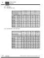
The following table shows the assignment of the EPL tot he zones:
Gas
Dust
EPL :
Category:
use in zone:
EPL :
Category:
use in zone:
Ga
1G
0
Da
1D
20
Gb
2G
1
Db
2D
21
Gc
3G
2
Dc
3D
22
With the revision of the IEC 60079 "electrical apparatus for potentially explosive atmospheres" the dust explosion protection has been integrated in this set of standards as
part 31. The separate dust standard IEC 61241-1 has become invalid with the release
of IEC 60079-31 in November 2008.
The international standard IEC 60079 will be harmonized as EN standard with the same
number and the same content in the foreseeable future.
The equipment group III for dust has also been implemented as part of this integration.
Thus there are 3 equipment groups in international standards:
Equipment group
Equipment for the use
I
In mine openings with a risk of firedamp (underground mining)
II
In areas with potentially explosive gas/air mixtures
III
In areas with potentially explosive dust/air mixtures
In addition, the new equipment group III has been split up into three subgroups "A", "B"
and "C" depending on the type of dust:
Equipment group
Suitable for atmospheres with
Minimum degree of protection
IP (x = placeholder)
IIIA
Flammable lint
5x
IIIB
Non-conducting dust
5x
IIIC
Conducting dust
6x
The specific values of equipment groups IIIA to IIIC for the dust/air mixture correspond
to the previous designation IIA to IIC for gas/air mixtures.
Previously, the designation IIA to IIC has only be used for motors in EX-d design (flameproof). Now, the designation of motors of a protection type with increased safety "e" is
changed from II (without letter) to IIA, IIB, or IIC. This implies demands on the prevention
of electrostatic charge of plastic surfaces, e.g. fans and coated, metal surfaces.
20
Operating Instructions – Explosion-Proof AC Motors EDR.71 – 225
Motor Structure
Explosion protection designations
3
The standard changes described above also cause a change of the EX designation of
motors that must also be specified on the motor nameplate. The following table lists
some examples:
Section
Previous designation
New designation
(ATEX)
With explosive gas/air
mixtures
With explosive dust/
air mixtures
(IECEx)
(until 2010)
(as of 2010)
(as of 2010)
II2G Ex e II T3
II2G Ex e IIC T3 Gb
Ex e IIC T3 Gb
II3G Ex nA II T3
II3G Ex nA IIC T3 Gc
Ex nA IIC T3 Gc
II2D Ex tD A21 IP65 T120°C
II2D Ex tb IIIC T120°C Db
Ex tb IIIC T120°C Db
II3D Ex tD A22 IP54 T120°C
II3D Ex tc IIIB T120°C Dc
Ex tc IIIB T120°C Dc
II3D Ex tD A22 IP65 T120°C
II3D Ex tc IIIC T120°C Dc
Ex tc IIIC T120°C Dc
With the designation of the explosion protection, you have to distinguish between the
designation according to Directive, e.g. II3D, and the designation according to standard,
e.g. Ex tc IIIC T120°C Dc.
II3D
Ex tc IIIC T120°C Dc
Designation according to standard
Designation according to directive
Equipment sold within the scope of the European Directive 94/9/EC must show the designation according to Directive 94/9/EC in addition to the standard designation. It is important to note that the Directive designation (e.g. with II) and the standard designation
(e.g. with II) are two different designations.
As the Directive contains both, the gas and the dust atmospheres in category II, a motor
is designated with II3D according to the Directive and IIIC according to the standard, for
example.
The new standard designation is to clearly and explicitly specify the zone and the mixture, the individual drive is approved for.
Operating Instructions – Explosion-Proof AC Motors EDR.71 – 225
21
Mechanical Installation
Before you start
4
4
Mechanical Installation
INFORMATION
Observe the safety notes in section 2 of these operating instructions for the mechanical installation.
4.1
Before you start
NOTICE
The mounting position for installation must correspond to the specifications on the
nameplate.
Only install the drive if the following conditions are met:
•
The specifications on the nameplate of the drive correspond to the supply system or
the output voltage of the frequency inverter
•
The drive is undamaged (no damage caused by transportation or storage)
•
All transport locks have been removed.
•
You are certain that the following requirements have been met:
– Ambient temperature between -20 °C and +40 °C.
Note that the temperature range of the gear unit may also be restricted (see gear
unit operating instructions)
Note that information on the nameplate may differ. The ambient conditions must
comply with all the specifications on the nameplate.
– No oil, acid, gas, vapors, radiation, etc.
– Installation altitude max. 1000 m above sea level
Observe chapter "Electrical Installation" > "Ambient conditions during operation"
> "Installation altitude".
– Note the restrictions for encoders
– Special design: Drive configured in accordance with the ambient conditions
The above mentioned information refers to standard orders. The conditions might be different when you order drives other than the standard. Observe any differing conditions
in the order confirmation.
22
Operating Instructions – Explosion-Proof AC Motors EDR.71 – 225
Mechanical Installation
Long-term storage of motors
4.2
4
Long-term storage of motors
•
Note that the service life of the lubricant in the ball bearings is reduced by 10% per
year after the first year of storage.
•
Before startup, you should re-lubricate the lubrication devices on motors that have
been in storage for longer than 5 years. Observe the information on the motor lubricant plate.
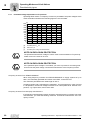
•
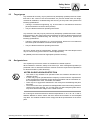
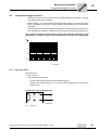
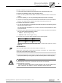
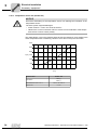
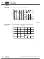
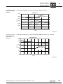
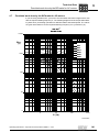
Check whether the motor has absorbed moisture as a result of being stored for a long
time. Measure the insulation resistance for this purpose (measuring voltage 500 V).
The insulation resistance (see following figure) varies greatly depending on the
temperature. The motor must be dried if the insulation resistance is not adequate.
[M ]
100
10
1
0,1
0
20
60
40
80
[˚C ]
173323019
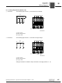
4.2.1
Drying the motor
Heat the motor:
•
With hot air or
•
Using isolation transformer
– Connect the windings in series (see following figures)
– Auxiliary AC voltage supply max. 10% of the rated voltage with max. 20% of the
rated current
Connection in wiring diagram R13:
[1]
2336250251
[1]
Transformer
Operating Instructions – Explosion-Proof AC Motors EDR.71 – 225
23
4
Mechanical Installation
Long-term storage of motors
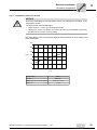
Connection in wiring diagram C13:
[1]
3955447819
[1]
Transformer
The drying process is finished when the minimum insulation resistance has been exceeded.
In the terminal box check that:
24
•
The inside is clean and dry
•
The connections and fixing parts are free from corrosion
•
The gasket and sealing surfaces are functioning
•
The cable glands are tight, otherwise clean or replace them
Operating Instructions – Explosion-Proof AC Motors EDR.71 – 225
Mechanical Installation
Motor installation notes
4.3
4
Motor installation notes
CAUTION
Sharp edges due to open keyway.
Minor injuries.
•
•
Insert key in keyway.
Pull protective sleeve over shaft.
CAUTION
Improper mounting may result in damages to the motor.
Possible damage to property
•
Note the following:
NOTICE
The mounting position for installation must correspond to the specifications on the
nameplate.
•
Motor shaft ends must be thoroughly cleaned of anti-corrosion agents, contamination
or similar (use a commercially available solvent). Do not allow the solvent to penetrate the bearings or shaft seals – this could damage the material.
•
Mount the gearmotor only on a level, vibration-free and torsionally rigid support structure.
•
Make sure the customer's counter-bearing is unobstructed and can move freely.
•
Align the motor and the driven machine carefully in order to prevent the output shaft
from being exposed to unacceptable strain. Observe the permitted overhung and
axial forces.
•
Do not jolt or hammer the shaft end.
Operating Instructions – Explosion-Proof AC Motors EDR.71 – 225
25
Mechanical Installation
Motor installation notes
4
•
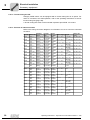
Check that there is sufficient clearance around the motor to provide for adequate
cooling, and that the motor does not suck in warm air from other devices. Observe
the following minimum clearance:
h
Motor type
EDR.71, EDR.80
h in mm
15
EDR.90, EDR.100
20
EDR.112, EDR.132
25
EDR.160
30
EDR.180
35
EDR.200, EDR.225
45
•
Balance components for subsequent mounting on the shaft with a half key (motor
shafts are balanced with a half key).
•
For brakemotors with manual brake release, screw in the manual lever (for HR selfreengaging manual brake release).
INFORMATION
•
•
•
4.3.1
26
If using belt pulleys:
– Only use belts that do not build up an electrostatic charge.
– Do not exceed the maximum permitted overhung load; for motors without gear
units, see chapter "Overhung loads (page 126)".
Motors in vertical mounting position (e.g. M4/V1) are equipped with a canopy /C as
standard.
On request, the motor can be delivered without canopy. In this case, you have to
install a cover when you install the drive in the plant/machine in order to prevent
objects from falling into the drive. Observe the requirements according to EN / IEC
60079-0 and EN / IEC 60079-7. This cover must not obstruct the cooling air supply.
For mounting positions with the motor output shaft pointing upwards (e.g. M2/V3),
you have to provide for a cover in order to prevent small objects from falling into
the fan guard, see EN / IEC 60079-0. This cover must not obstruct the cooling air
supply.
Installation in damp locations or in the open
•
Use suitable cable glands for the incoming cable (use reducing adapters if necessary) according to the installation instructions.
•
If possible, arrange the terminal box so that the cable entries are pointing downwards.
•
Seal the cable entry properly.
•
Clean the sealing surfaces of the terminal box and the terminal box cover carefully
before re-assembly; replace embrittled gaskets.
•
If required, touch up the corrosion protection (especially at the eyebolts).
•
Check the degree of protection.
•
Protect the shaft against corrosion with a suitable anti-corrosion agent.
Operating Instructions – Explosion-Proof AC Motors EDR.71 – 225
Mechanical Installation
Mounting tolerances
4.4
4.5
4
Mounting tolerances
Shaft end
Flanges
Diameter tolerance according to EN 50347
• ISO j6 with Ø ≤ 28 mm
• ISO k6 with Ø ≥ 38 mm up to ≤ 48 mm
• ISO m6 at Ø ≥ 55 mm
• Center bore in accordance with DIN 332, shape
DR..
Centering shoulder tolerance in accordance with
EN 50347
• ISO j6 with Ø ≤ 250 mm
• ISO h6 with Ø ≥ 300 mm
Assembling the input elements
Input elements that are mounted on the motor shaft end, e.g. pinions, must be warmed
up prior to assembly in order to prevent damages to the encoder of stand-alone motors.
4.6
Non-SEW encoder mounting
If a drive was ordered with non-SEW encoder, SEW-EURODRIVE will deliver the drive
with enclosed coupling. You must not connect the coupling for operation without nonSEW encoder.
Operating Instructions – Explosion-Proof AC Motors EDR.71 – 225
27
Mechanical Installation
Connecting XV.A encoder mounting adapter to EDR.71 – 225 motors
4
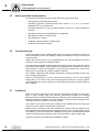
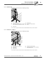
4.7
Connecting XV.A encoder mounting adapter to EDR.71 – 225 motors
If you have ordered the XV.A encoder mounting adapter, the adapter and the coupling
are enclosed with the motor and are to be assembled by the customer.
The following figure shows how to assemble the coupling and the adapter:
[212]
[225]
[E]
[D]
[C]
[B]
[A]
[220]
[F]
[E]
[D]
[C]
[B]
[269]
[22]
[361] / [170]
[A]
[251] [232]
3633163787
[22]
[170]
[212]
[220]
[225]
[232]
[251]
Screw
forced cooling fan guard
Fan guard with encoder mount
Encoder
Intermediate flange (not with XV1A)
Screws (only with XV1A and XV2A)
Conical spring washers (only with XV1A
and XV2A)
[361]
[269]
[A]
[B]
[C]
[D]
[E]
[F]
Extended fan guard
Grommet
Adapter
Retaining screw
Central retaining screw
Coupling (spread- or solid shaft coupling)
Retaining screw
Screw
1. If available, remove cover [361] or forced cooling fan guard [170].
2. For XV2A and XV4A: Remove intermediate flange [225].
3. Screw in the coupling [D] into the encoder bore of the motor shaft with the screw [C].
EDR.71 – 132: Tighten the screw [C] with a tightening torque of 3 Nm [26,6 lb-in].
EDR.160 – 225: Tighten the screw [C] with a tightening torque of 8 Nm [70,8 lb-in].
4. Push the adapter [A] on the encoder [220] and tighten it with the retaining screw [B]
with a tightening torque of 3 Nm [26.6 lb-in].
28
Operating Instructions – Explosion-Proof AC Motors EDR.71 – 225
Mechanical Installation
Connecting XV.A encoder mounting adapter to EDR.71 – 225 motors
4
5. For XV2A and XV4A: Mount the intermediate flange [225] with the screw [F] with a
tightening torque of 3 Nm [26.6 lb-in].
6. Push the encoder and the adapter on the coupling [D] and tighten the retaining screw
[E] with a tightening torque of 3 Nm [26.6 lb-in].
7. With XV1A and XV2A: Arrange conical spring washers [251] with retaining screws
[232] and place in annular groove of the encoder [220] and tighten with a tightening
torque of 3 Nm (26.6 lb-in).
8. For XV3A and XV4A: Installation by the customer via the bores in the encoder plate.
4.7.1
XH.A encoder mounting adapter
The XH1A, XH7A and XH8A encoder mounting adapters for hollow shaft encoders are
premounted on delivery.
Proceed according to chapter "Motor and brake maintenance – preliminary work"
(page 96) to mount the encoder.
Operating Instructions – Explosion-Proof AC Motors EDR.71 – 225
29
Mechanical Installation
Turning the terminal box
4
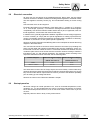
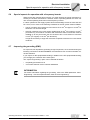
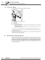
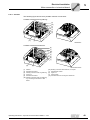
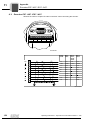
4.8
Turning the terminal box
4.8.1
Terminal box with tension spring terminal power connections
The following figure shows the terminal box variant with tension spring terminal strip:
[123]
[131]
[119]
[b]
[a]
[111]
[c]
2752242955
[111]
[119]
[123]
[131]
[a]
[b]
[c]
Seal
Terminal box retaining screws + lock washers (4 x each)
Terminal box cover retaining screws + lock washers (4 x each)
Seal
Terminal strip 1
Terminal strip 2 + retaining plate
Power terminal
The type and number of terminal strips varies with the terminal box design and the options.
30
Operating Instructions – Explosion-Proof AC Motors EDR.71 – 225
Mechanical Installation
Turning the terminal box
4
Proceed as follows to turn the terminal box:
1. Loosen the screws [123] from the terminal box cover and remove the cover.
2. Loosen the retaining screws [119] and the terminal box.
3. Clean the sealing surfaces at the stator shoulder, the bottom and the cover of terminal box.
4. Check the gaskets [111 and 131] for damages and replace them if necessary.
5. Position the terminal box as desired.
6. If the terminal strip 2 [b] has been installed with the retaining screws of the terminal
box [119], it must be mounted again to the face of the power terminal after the terminal box has been turned.
INFORMATION
Connection alternatives for 2 terminal strips [a] and [b] are listed in the appendix
(page 159).
7. Fasten the bottom part of the terminal box with the screws [119] and the lock washers
with one of the following tightening torques:
•
EDR.71 – 132: 5 Nm [44,3 lb-in]
•
EDR.160 – 225: 25.5 Nm [225.7 lb-in]
8. Fasten the terminal box cover with the screws [123] and the lock washers with the
appropriate tightening torque. Make sure the gasket is seated properly.
Operating Instructions – Explosion-Proof AC Motors EDR.71 – 225
31
Mechanical Installation
Turning the terminal box
4
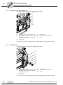
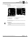
4.8.2
Terminal box with terminal board and anti-twist frame
The following figure shows a terminal box with anti-twist frame:
[123]
[131]
[1213]
[119]
[a]
[b]
[111]
9007202073806603
[111] Seal
[119] Terminal box retaining screws + lock washers (4 x each)
[123] Terminal box cover retaining screws + lock washers (4 x each)
[131] Seal
[a]
Terminal strip 1
[b]
Terminal strip 2
[1213] Kit (1 anti-twist frame, 1 terminal board, 4 sleeves, 2 screws, 2 nuts)
The type and number of terminal strips varies with the terminal box design and the options.
32
Operating Instructions – Explosion-Proof AC Motors EDR.71 – 225
Mechanical Installation
Turning the terminal box
4
Proceed as follows to turn the terminal box:
1. Loosen the screws [123] from the terminal box cover and remove the cover.
2. Remove the retaining screws [119] of the terminal box.
3. Clean the sealing surfaces at the stator shoulder, the bottom and the cover of terminal box.
4. Check the gaskets [111 and 131] for damages and replace them if necessary.
5. Take the unit consisting of terminal board and anti-twist frame from the terminal box.
Remove any cables that are already connected before taking out the unit.
6. Position the terminal box as desired.
7. Turn the unit consisting of terminal board and anti-twist frame in the same way as the
terminal box and put it back in.
The terminal board designations U1, V1 and W1 must be pointing towards the cable
outputs afterwards.
8. Fasten the bottom part of the terminal box with the screws [119] and the lock washers
with one of the following tightening torques:
•
EDR.71 – 132: 5 Nm [44,3 lb-in]
•
EDR.160 – 225: 25.5 Nm [225.7 lb-in]
9. Re-connect any removed cables according to the following table:
Yellow
White
W2/T4
U2/T5
Brown
V2/T6
Black
Red
Blue
U1/T1
V1/T2
W1/T3
Tighten the nuts on the connection bolts with the appropriate tightening torque
(page 34).
INFORMATION
The connected cables must be free from bends and twists, etc.
Observe the correct order of the small connection accessories, see chapter "Motor
connection via terminal board" (page 48).
10.Fasten the terminal box cover with the screws [123] and the lock washers with the
appropriate tightening torque (page 34). Make sure the gasket is seated properly.
WARNING
Possible damage to the motor outputs when turning the terminal board.
Possible damage to property.
•
To make sure that the cables have not been damaged, carry out an insulation test
after re-assembly, see chapter "Long-term storage of motors" (page 23).
Operating Instructions – Explosion-Proof AC Motors EDR.71 – 225
33
Mechanical Installation
Coating
4
4.8.3
Tightening torques
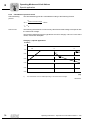
The following table shows all the tightening torques required for this procedure:
Key number
Screw
Area of application
[2]
Terminal stud nut
M6 stud
in Nm
in lb-in
3
26.6
M8 stud
6
53.1
M12 stud
15.5
137.2
[113]
Pan head screw DIN rail connection
EDR.71 – 132
5
44.3
[117]
Hex head screw grounding inside
EDR.71 – 132
4
35.4
EDR.160
25.5
225.7
EDR.180 – 225 (aluminum design)
25.5
225.7
EDR.180 – 225 (graycast iron design)
50
442.5
[119]
[123]
4.9
Tightening torque
Pan head screw of terminal box
Hex head screw terminal box cover
EDR.71 – 132
5
44.3
EDR.160 – 225
25.5
225.7
EDR.71 – 132
4
35.4
EDR.160
10.3
91.2
EDR.180 – 225 (aluminum design)
10.3
91.2
EDR.180 – 225 (graycast iron design)
25.5
225.7
16.0
[137]
Screw option terminal
EDR.71 – 225
1.8
[140]
Hex head screw grounding outside
EDR.71 – 225
4
35.4
[151]
Flat head screw option terminal
EDR.71 – 225
1
8.9
[632]
Pan head screw option terminal
EDR.71 – 225
1.8
16.0
Coating
NOTE ON EXPLOSION PROTECTION
SEW-EURODRIVE delivers the drives with a coating that complies with the requirements regarding the prevention of electrostatic charge according to EN / IEC 600790. If you recoat the motors or gearmotors, you have to observe the requirements regarding the prevention of electrostatic charge according to EN / IEC 60079-0 .
4.10
Additional features
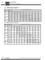
The following additional features are used depending on the respective category, see
the following table:
Category 2
34
Category 3
2. Shaft end with optional cover
x
x
2. Shaft end without optional cover
x
x
Operating Instructions – Explosion-Proof AC Motors EDR.71 – 225
Mechanical Installation
Additional features
4
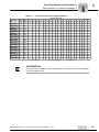
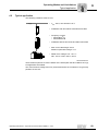
4.10.1 2. Shaft end
As standard, SEW-EURODRIVE supplies the accessory equipment "second shaft end"
with inserted key and additional protection by means of a tape. No cover is supplied as
standard. The cover can be ordered separately.
With optional cover
Sizes EDR.71 – EDR.132 come equipped with a cover.
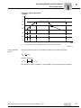
The following figure shows the dimensions of the covers:
Sizes EDR.71 – EDR.132
[34]
[33]
DA
[361]
EA
[4]
> 1 mm
L3
L2
LB / LBS 1)
L4
2634738827
[4]
[33]
[34]
Keyway
Washer
Tapping screw
LB/LBS Length of the motor/brakemotor
1)
Refer to the catalog for dimensions
[361]
Extended fan guard
Motor size
DA
EA
L2
L3
L4
EDR.71
11
23
80
2
91.5
EDR.80
14
30
93
2
95.5
EDR.90
14
30
86.5
2
89
EDR.100
14
30
86.5
2
89
EDR.112/132
19
40
122.5
3.5
125
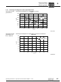
Observe the distances between the shaft shoulder and the fan housing as well as the
overhung loads when you connect accessories.
Operating Instructions – Explosion-Proof AC Motors EDR.71 – 225
35
Mechanical Installation
Additional features
4
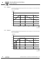
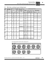
The following table shows the distances between the shaft shoulder and the fan housing:
Length of the 2. shaft end in
mm
Distance between shaft shoulder and fan housing in mm
71
23
2
80
30
2
90
30
2
100
30
2
112
40
3.5
132
40
3.5
Motor size
Without optional
cover
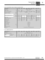
Variants without cover must be provided with a cover by the customer.
Observe the impact resistance requirements according to EN / IEC 60079-0 when you
select and mount the cover.
CAUTION
protective cover missing or incorrect.
Severe or fatal injuries.
•
•
36
Only qualified personnel may mount the protective cover.
Only start up the motor with the correct protective cover.
Operating Instructions – Explosion-Proof AC Motors EDR.71 – 225
Electrical Installation
Additional regulations
5
5
Electrical Installation
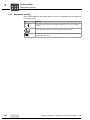
WARNING
Danger of electric shock.
Severe or fatal injuries!
•
5.1
Note the following:
•
It is essential to comply with the safety notes in chapter 2 during installation!
•
Use switch contacts in utilization category AC-3 according to EN 60947-4-1 for
switching the motor.
•
When motors are powered by inverters, you must adhere to the wiring instructions
issued by the inverter manufacturer.
•
Observe the operating instructions of the inverter.
Additional regulations
The generally applicable installation regulations for low-voltage electric equipment (such
as DIN IEC 60364, DIN EN 50110) must be complied with when setting up electrical machinery.
5.2
Wiring diagrams and terminal assignment diagrams
Connect the motor only as shown in the wiring diagram(s) included with the motor. Do
not connect or start up the motor if the wiring diagram is missing. You can obtain the
valid wiring diagrams free of charge from SEW-EURODRIVE.
5.3
Cable entries
The terminal boxes have metric threaded holes according to EN 50262 or NPT threaded
holes according to ANSI B1.20.1-1983. All bores are equipped with explosion-proof
closing plugs upon delivery.
In order to provide for a correct cable entry, you have to replace the closing plugs with
cable glands with strain relief, that are certified for the use in the respective explosionproof zone. Select the cable screw fitting according to the outer diameter of the cable
used. For the tightening torque of the cable entry, refer to the operating/installation instructions or the EC prototype test certificate of the cable glands. The IP degree of protection of the cable entry must be at least as high as the IP degree of protection of the
motor.
Operating Instructions – Explosion-Proof AC Motors EDR.71 – 225
37
Electrical Installation
Equipotential bonding
5
Only use connection glands with screw heads that fit into the existing counter sinking
The following table shows the sizes of the flat bottom counter sinking with the corresponding screw sizes:
Counter sinking in mm
Screw fitting
22
M16
30
M20
34
M25
41
M32
53
M40
62
M50
77
M63
All cable entries that are not required must be sealed off with a closing plug after completion of the installation in order to maintain the degree of protection. A closing plug
may only be replaced with another explosion-proof closing plug.
5.4
Equipotential bonding
In accordance with EN 60079-14 and IEC 61241-14, it might be necessary to establish
a connection to an equipotential bonding system. Observe the chapter "Electrical Installation" / "Improving the grounding (EMC)".
5.5
Wiring notes
Comply with the safety notes during installation.
5.5.1
Protecting the brake control system against interference
Unless they are shielded, brake cables must always be routed separately from other
power cables with phased currents to protect brake controls against interference. Power
cables with phased currents are in particular
5.5.2
•
Output cables from frequency inverters and servo controllers, soft start units and
brake units
•
Supply cables for braking resistors and similar options
Protecting the motor protection devices against interference
To protect against interference by SEW motor protection devices (temperature sensors
TF, winding thermostats TH):
38
•
You may route separately shielded supply cables together with switched-mode
power lines in one cable.
•
You must not route unshielded supply cables together with switched-mode power
lines in one cable.
Operating Instructions – Explosion-Proof AC Motors EDR.71 – 225
Electrical Installation
Special aspects for operation with a frequency inverter
5.6
5
Special aspects for operation with a frequency inverter
When motors are powered from inverters, you must observe the wiring instructions issued by the inverter manufacturer. Observe section "Operating Modes and Limit Values" and the operating instructions of the frequency inverter.
If a drive operated on the supply system has an earth-leakage current of more than AC/
DC 10 mA, one or more of the following conditions for the PE system must be fulfilled:
•
The PE conductor has a minimum cross section of 10 mm2 for copper or 16 mm2 for
aluminum over its entire length.
•
If the PE conductor has a cross section smaller than 10 mm2 (for copper) or 16 mm2
(for aluminum), a second PE conductor with at least the same cross section must be
installed up to the point where the PE conductor has a cross section of minimum
10 mm2 (for copper) or 16 mm2 (for aluminum).
It might be necessary to equip the drive with a separate connection for a second PE
conductor.
5.7
Improving the grounding (EMC)
For improved, low-impedance grounding at high frequencies, we recommend using the
following connections: SEW-EURODRIVE recommends to use corrosion-resistant connection elements.
If you require an NF equipotential bonding in addition to the HF equipotential bonding,
you can apply the conductor at the same point.
The "Improved grounding" option can be ordered as follows:
•
completely premounted or as
•
"connection element" kit for customer installation
INFORMATION
For further information regarding the grounding, refer to the SEW publication "Drive
Engineering – Practical Implementation, EMC in Drive Engineering".
Operating Instructions – Explosion-Proof AC Motors EDR.71 – 225
39
Electrical Installation
Improving the grounding (EMC)
5
5.7.1
Size EDR.71S / M and EDR.80S / M
The following figure shows how to install the grounding:
[1]
[2]
[3]
[4]
[5]
[6]
[1]
[2]
Use of the pre-cast bore at the terminal-box
[4]
recess/foot
Grounding element with self-tapping screw DIN [5]
7500 M6 x 10, customer M8 x 16, tightening
[6]
torque 6 Nm (53.1 lb-in)
[3]
Ground strap
Disk ISO 7090
Serrated lock washer DIN 6798
M8 nut
You can order the complete connection element from SEW-EURODRIVE with part number 13633953.
5.7.2
Size EDR.90M / L
The following figure shows how to install the grounding:
[1]
[2]
[3]
[4]
[5]
[6]
[1]
[2]
Use of the pre-cast bore
[4]
Grounding element with self-tapping screw DIN [5]
7500 M6 x 10, customer M8 x 16, tightening
[6]
torque 6 Nm (53.1 lb-in)
[3]
Ground strap
Disk ISO 7090
Serrated lock washer DIN 6798
M8 nut
You can order the complete connection element from SEW-EURODRIVE with part number 13633953.
40
Operating Instructions – Explosion-Proof AC Motors EDR.71 – 225
Electrical Installation
Improving the grounding (EMC)
5.7.3
5
Size EDR.100M
The following figure shows how to install the grounding:
[1]
[2]
[3]
[4]
[5]
[6]
[1]
[2]
Use of the pre-cast bore
[4]
Self-tapping screw DIN 7500 M6 x 10, customer [5]
M8 x 16, tightening torque 6 Nm (53.1 lb-in)
[6]
[3]
Ground strap
Disk ISO 7090
Serrated lock washer DIN 6798
M8 nut
You can order the complete connection element from SEW-EURODRIVE with part number 13633953.
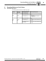
5.7.4
Size EDR.100L – EDR.132
The following figure shows how to install the grounding:
[1]
[2]
[3]
[4]
[5]
[6]
[1]
[2]
[3]
[4]
Use of tapped hole for lifting eyes
Disk ISO 7090
Ground strap
Disk ISO 7090
[5]
[6]
Serrated lock washer DIN 6798
Hex head screw ISO 4017 M8 x 16, tightening
torque 6 Nm (53.1 lb-in)
You can order the complete connection element from SEW-EURODRIVE with part number 13633945.
Operating Instructions – Explosion-Proof AC Motors EDR.71 – 225
41
Electrical Installation
Special aspects in switching operation
5
5.7.5
Sizes EDR.160 – EDR.225
The following figure shows how to install the grounding:
[1]
[2]
[3]
[4]
[5]
[6]
[1]
[2]
[3]
[4]
[5]
[6]
Use of the tapped holes at the terminal box
Disk ISO 7090
Ground strap
Disk ISO 7090
Serrated lock washer DIN 6798
• Hex head screw ISO 4017 M8 x 16 (with aluminum terminal boxes size EDR.160 – 225), tightening
torque 6 Nm (53.1 lb-in)
• Hex head screw ISO 4017 M10 x 25 (with gray cast iron terminal boxes size EDR.160 – 225), tightening torque 10 Nm (88.5 lb-in)
You can order the complete connection element from SEW-EURODRIVE with part number 13633945.
For sizes EDR.160 – 225 with gray cast iron terminal boxes, the grounding is always
pre-installed upon delivery.
For aluminum terminal boxes size EDR.160 – 225, you can order the "connection element" kit with part number 13633945.
5.8
Special aspects in switching operation
When the motors are used in switching operation, possible interference of the switchgear must be excluded by ensuring suitable wiring. According to EN 60204 (electrical
equipment of machines), motor windings must have interference suppression to protect
the numerical or programmable logic controllers. As it is primarily switching operations
that cause interference, SEW-EURODRIVE recommends installing protective circuitry
in the switching devices.
42
Operating Instructions – Explosion-Proof AC Motors EDR.71 – 225
Electrical Installation
Ambient conditions during operation
5.9
Ambient conditions during operation
5.9.1
Ambient temperature
5
Unless otherwise specified on the nameplate, you must observe the temperature range
of -20 °C to +40 °C.
Motors intended for use in higher or lower ambient temperatures have specific designations on the nameplate.
If the motors are used at temperatures above +40 °C (max. +60 °C), the cables and
cable glands must be suited for temperatures ≥ 90 °C.
Temperatures below -20 °C (max. -40 °C) require an anti-condensation heating. In addition, the cables and cable glands must me selected according to the respective temperature.
5.9.2
Installation altitude
The maximum installation altitude of 1000 m above sea level must not be exceeded.
5.9.3
Hazardous radiation
Motors must not be subjected to hazardous radiation (such as ionizing radiation). Contact SEW-EURODRIVE if necessary.
5.9.4
Harmful gas, vapor and dust
If used according to their designated use, explosion-proof motors are incapable of igniting explosive gases, vapors or dusts. However, explosion-proof motors may not be subjected to gases, vapors or dusts that endanger operational safety, for example through
Gasket selection
•
Corrosion
•
Damage to the protective coating
•
Damage to the sealing material, etc.
If the motor is operated in environments with high environmental impact, such as increased ozone values, EDR motors can be equipped with high-quality gaskets. If you
have doubts regarding the stability of the gaskets in connection with the respective environmental impacts, consult SEW-EURODRIVE.
Operating Instructions – Explosion-Proof AC Motors EDR.71 – 225
43
Electrical Installation
Motors of categories 2GD and 3GD
5
5.10
Motors of categories 2GD and 3GD
5.10.1 General information
The explosion-proof SEW-EURODRIVE motors of the EDR.. series are designed for the
following application zones.
Motor category
Operating range
2GD
Application in zone 1 or zone 21 and compliance with the design requirements for
equipment group II, category 2GD.
3GD
Application in zone 2 or 22 and compliance with the design requirements for
equipment group II, category 3GD.
5.10.2 Special indication "X"
If the special indication "X" appears after the certification number on the declaration of
conformity or the prototype test certificate, this indicates the certificate contains special
conditions for safe application of the motors.
5.10.3 Temperature classes
The motors are authorized for temperature classes T3 and T4. The temperature class
of the motor variant 3GD is listed on the nameplate or in the declaration of conformity in
the appendix.
The temperature class of the motor variant 2GD is listed in the type examination certificate that is enclosed with each motor.
5.10.4 Surface temperatures
The surface temperature of the motor can be found on the nameplate, the declaration
of conformity or the prototype test certificate.
5.10.5 Protection against impermissibly high surface temperatures
Explosion-proof motors in ensure safe operation under normal operating conditions. The
motor must be switched off securely in the case of overload to avoid the risk of impermissibly high surface temperatures.
The motor protection must comply with the respective approvals. There are 2 basic
motor protection types. The respective options can be added if available:
44
Motor protection types
Option
A: Motor current circuit breaker
TF, KY or PT
B: PTC thermistor
(PTC resistor: SEW designation: TF)
KY or PT
Operating Instructions – Explosion-Proof AC Motors EDR.71 – 225
Electrical Installation
Motors of categories 2GD and 3GD
5
The following table shows the type of motor protection required according to the respective approval:
Category
Operation:
Labeling
(see nameplate):
Motor protection via
2 (2GD / Gb Db)
3 (3GD / Gc Dc)
Supply
system
Frequency
inverter
Pulsed
Supply
system
Frequency
inverter
Pulsed
Te time
Te time
Ta time
–
–
–
A
B
B
A
B
B
For permitted operating modes depending on the motor protection, see chapter "Permitted operating modes" (page 59). Brakemotors in category 3GD from SEW-EURODRIVE
are equipped with PTC thermistors (TF) at the factory.
5.10.6 Protection only with motor protection switch
Note the following when installing the motor protection switch to EN 60947:
•
With category 2GD: With starting current ratio IA/IN listed on the nameplate, the response time of the motor protection switch must be less than the tE time of the motor.
•
The motor protection switch must disconnect all poles in the event of a phase failure.
•
The motor protection switch must be approved by a notified body and assigned a corresponding inspection number.
•
The motor protection switch must be set to the rated motor current indicated on the
nameplate. With category 2GD, the permitted nominal motor current is specified on
the prototype test certificate.
5.10.7 Protection exclusively with PTC temperature sensors (TF)
The positive coefficient thermistor must be evaluated using a suitable device. Observe
the applicable installation regulations.
CAUTION
Damage to the temperature sensor due to excessive voltage.
Possible destruction of the temperature sensor.
•
Do not apply any voltages > 30 V
The PTC thermistors comply with DIN 44082.
Resistance measurement (measuring instrument with V ≤ 2.5 V or I < 1 mA):
•
Standard measured values: 20 – 500 Ω, thermal resistance > 4000 Ω
The PTC thermistor (TF) is required in order to maintain a safe isolation and for thermal
monitoring.
The evaluation function of the temperature monitoring must be activated in connection
with the temperature sensor measuring circuit and must become effective in the event
of an overtemperature.
Operating Instructions – Explosion-Proof AC Motors EDR.71 – 225
45
5
Electrical Installation
Motors of categories 2GD and 3GD
5.10.8 Protection with motor protection switch and additional PTC thermistor
The conditions stated for exclusive protection with motor protection switches also apply
here. Protection with positive temperature coefficient thermistors (TF) only represents a
supplementary protection measure which is irrelevant to certification for potentially explosive atmospheres.
INFORMATION
Proof of the efficacy of the installed protective equipment is required prior to startup.
46
Operating Instructions – Explosion-Proof AC Motors EDR.71 – 225
Electrical Installation
Notes on motor connection
5.11
5
Notes on motor connection
INFORMATION
It is essential to comply with the valid wiring diagram! Do not connect or start up the
motor if this wiring diagram is missing. You can obtain the valid wiring diagrams free
of charge from SEW-EURODRIVE.
INFORMATION
The terminal box must be free of foreign objects, dirt and humidity. Unused cable entry
openings and the terminal box itself must be closed so they are dust and water-proof.
Observe the following points when you connect the motor:
•
Check cable cross section
•
Arrange terminal links correctly
•
Properly tighten connections and protective earth
•
Check that the connection cables are not cramped in order not to damage the insulation.
•
Observe clearances, see chapter "Electrical connection" (page 37)
•
In the terminal box: Check winding connections and tighten them if necessary
•
Perform the connection in accordance with the enclosed wiring diagram
•
Avoid protruding wire ends
•
Observe the specified direction of rotation
The following wiring diagrams can be obtained from SEW-EURODRIVE by specifying
the motor order number (see chapter "Nameplate, type designation"):
Series
Number of poles
Connection
EDR.71-225
4
/
Associated wiring diagram
(designation/number)
xx = placeholder for the version
C13: 68 184 xx 08
R13: 68 001 xx 06
The motors are supplied and connected differently depending on the size and electrical
design. Comply with the connection type specified in the following table:
Series
Connection
EDR.71 – EDR.132
•
•
With V < 500 V and I < 17 A: Motor connection via tension spring terminal strip
With V > 500 V and I > 17 A: Motor connection via terminal board
EDR.160 – EDR.225
•
Motor connection via terminal board
Observe the permitted air and creeping distances when connecting the supply system
cable.
Operating Instructions – Explosion-Proof AC Motors EDR.71 – 225
47
Electrical Installation
Motor connection via terminal board
5
5.12
Motor connection via terminal board
The motors are supplied and connected differently depending on the electrical design.
Arrange the cables and terminal links as shown in the wiring diagram and screw them
on firmly. Observe the tightening torques specified in the following tables:
Motor sizes EDR.71 – EDR.132
Terminal
stud
Tightening
torque of hex nut
Ø
M6
M6
Connection
Customer
Variant
Connection
type
Scope of delivery
Cross section
PE connection stud
Variant
Ø
3.0 Nm
(26.5 lb-in)
≤ 6 mm2
(AWG 10)
1
3.0 Nm
(26.5 lb-in)
≤ 35 mm2
(AWG 2)
1
Ring cable lug
or solid wire
Small connection
accessories
enclosed in bag
M5
2
Ring cable lug
Small connection
accessories
enclosed in bag
M5
2
PE connection stud
Variant
Motor size EDR.160
Terminal
stud
Tightening
torque of hex nut
Ø
M6
M6
M8
Customer
connection
Variant
Connection
type
Scope of delivery
Cross section
Ø
3.0 Nm
(26.5 lb-in)
≤ 6 mm2
(AWG 10)
1
3.0 Nm
(26.5 lb-in)
≤ 35 mm2
(AWG 2)
1
6.0 Nm
(53.1 lb-in)
≤ 70 mm2
(AWG 2/0)
1
Ring cable lug
or solid wire
Small connection
accessories
enclosed in bag
M8
2
Ring cable lug
Small connection
accessories
enclosed in bag
M8
2
Small connection
accessories
enclosed in bag
M10
2
PE connection stud
Variant
Ring cable lug
Motor sizes EDR.180 – EDR.225
Terminal
stud
Tightening
torque of hex nut
Ø
M6
M8
M12
Customer
connection
Variant
Connection
type
Scope of delivery
Cross section
Ø
3.0 Nm
(26.5 lb-in)
≤ 6 mm2
(AWG 10)
1
6.0 Nm
(53.1 lb-in)
≤ 70 mm2
(AWG 2/0)
1
15.5 Nm
(137.2 lb-in)
35 mm2
(AWG 2) –
95 mm2
(AWG 3/0)
1
Ring cable lug
or solid wire
Small connection
accessories
enclosed in bag
M8
2
Ring cable lug
Small connection
accessories
enclosed in bag
M8
2
Connection parts
pre-assembled
M12
2
Ring cable lug
The designs in bold print apply to S1 operation for the standard voltages and standard
frequencies according to the data in the catalog. Other versions may have different connections, for example different terminal stud diameters and/or a different scope of delivery.
NOTE ON EXPLOSION PROTECTION
Tubular cable lugs according to DIN 46235 must not be used as they may not comply
with the permitted minimum clearances.
48
Operating Instructions – Explosion-Proof AC Motors EDR.71 – 225
Electrical Installation
Motor connection via terminal board
5
5.12.1 Variant 1
The following figure shows the 2 possible customer connections:
Customer connection with ring cable lug:
[8]
[6a]
[5]
[4]
[3]
[2]
[1]
[9]
[10]
3989525643
Customer connection with solid wire:
[8]
[7]
[6b]
[5]
[4]
[3]
[2]
[1]
[10]
[9]
9007201889135499
[1]
[2]
[3]
[4]
[5]
[6a]
Washer
Serrated lock washer
Winding connection with ring cable lug
Lower nut
Serrated lock washer
Winding connection with ring cable lug,
e.g. according to DIN 46237 or DIN
46234.
[6b]
[7]
[8]
[9]
[10]
Operating Instructions – Explosion-Proof AC Motors EDR.71 – 225
Winding connection with solid wire, U-shaped
Serrated lock washer
Upper nut
Terminal stud
Anti-twist frame for ensuring the clearances
49
5
Electrical Installation
Motor connection via terminal board
5.12.2 Variant 2
The following figure shows the variant for PE connection:
[1]
[2]
[1]
[3]
[2]
[4]
[5]
[3]
[4]
[5]
[6]
[6]
9007202075543051
[1]
[2]
[3]
50
Hex nut
Washer
PE conductor with cable lug
[4]
[5]
[6]
Serrated lock washer
Stud
Terminal box
Operating Instructions – Explosion-Proof AC Motors EDR.71 – 225
Electrical Installation
Connecting the motor via terminal strip
5.13
5
Connecting the motor via terminal strip
5.13.1 KCC terminal strip
•
Perform the connection in accordance with the enclosed wiring diagram
•
Check the maximum cable cross section:
– 4 mm2 (AWG 12) rigid
– 4 mm2 (AWG 12) flexible
– 2,5 mm2 (AWG 14) flexible with conductor end sleeve
•
In the terminal box: Check winding connections and tighten them if necessary
•
Strip-off length 10-12 mm
Arrangement of terminal links for connection
Arrangement of terminal links for connection
Operating Instructions – Explosion-Proof AC Motors EDR.71 – 225
51
Electrical Installation
Connecting the brake
5
5.14
Connecting the brake
The brake is released electrically. The brake is applied mechanically when the voltage
is switched off.
WARNING
Risk of crushing if the hoist falls.
Severe or fatal injuries.
•
•
•
Comply with the applicable regulations issued by the relevant employer's liability
insurance association regarding phase failure protection and the associated circuit/
circuit modification!
Connect the brake according to the provided wiring diagram.
In view of the DC voltage to be switched and the high level of current load, it is essential to use either special brake contactors or AC contactors with contacts in utilization category AC-3 according to EN 60947-4-1.
5.14.1 Connecting the brake control
The DC disk brake is powered from a brake control system with protection circuit. The
brake controller is installed in the control cabinet.
52
•
Check the cable cross sections – brake currents (see chapter "Technical
Data")
•
Connect the brake controller according to the wiring diagram supplied with the brake.
•
For brakemotors of category 3GD, the brake rectifier must be installed in the control
cabinet.
•
Brakes must not be opened electrically all the time while the motor is at standstill.
Operating Instructions – Explosion-Proof AC Motors EDR.71 – 225
Electrical Installation
Accessory equipment
5.15
5
Accessory equipment
Connect accessory equipment as shown in the wiring connection diagram(s) provided
with the motor. Do not connect or start up the accessory equipment if the wiring
diagram is missing. You can obtain the valid wiring diagrams from SEW-EURODRIVE
free of charge.
The following additional features are used depending on the respective category, see
the following table:
Optional equipment
Category 2
Category 3
Temperature sensor /TF
x
x
Temperature sensor /KY
x
x
Temperature sensor /PT
x
x
Forced cooling fan /VE
–
x
Add-on encoders
–
x
Anti-condensation heater
x
x
5.15.1 Temperature sensor /TF
NOTICE
Damage of the temperature sensor due to excessive heat.
The drive system might be damaged.
•
Do not apply voltages > 30 V to the TF temperature sensor.
The PTC thermistors comply with DIN 44082.
Resistance measurement (measuring instrument with V ≤ 2.5 V or I < 1 mA):
•
Standard measured values: 20...500 Ω, thermal resistance > 4000 Ω
When using the temperature sensor for thermal monitoring, the evaluation function must
be activated to maintain reliable isolation of the temperature sensor circuit. If the temperature reaches an excessive level, a thermal protection function must be triggered immediately.
If there is a second terminal box for the TF temperature sensor, you must connect the
temperature sensor in that terminal box.
Operating Instructions – Explosion-Proof AC Motors EDR.71 – 225
53
5
Electrical Installation
Accessory equipment
5.15.2 Temperature sensor /KY (KTY84-130)
NOTICE
Excessive self-heating of the temperature sensor can damage the insulation of the
temperature sensor.
The drive system might be damaged.
•
•
Avoid currents > 4 mA in the circuit of the KTY.
Observe the correct connection of KTY to ensure correct evaluation of the temperature sensor. Ensure correct polarity.
The characteristic curve in the following figure shows the resistance curve subject to the
motor temperature with a measuring current of 2 mA and correct pole connection.
3000
2500
2000
R [Ω] 1500
1000
500
0
-100
-50
0
50
100
150
200
-250
300
350
T [°C]
Technical data
Connection
Total resistance at 20 - 25 °C
Test current
54
KTY84 - 130
Red (+)
Blue (-)
540 Ω < R < 640 Ω
< 3 mA
Operating Instructions – Explosion-Proof AC Motors EDR.71 – 225
Electrical Installation
Accessory equipment
5
5.15.3 Temperature sensor /PT (PT100)
NOTICE
Excessive self-heating of the temperature sensor can damage the insulation of the
temperature sensor.
The drive system might be damaged.
•
•
Avoid currents > 4 mA in the circuit of the PT100.
Observe the correct connection of PT100 to ensure correct evaluation of the temperature sensor. Ensure correct polarity.
The characteristic curve in the following figure shows the resistance curve subject to the
motor temperature.
300
250
200
R [Ω]
150
100
50
0
-100
-50
0
50
100
150
200
250
T [°C]
Technical data
Connection
Resistance at 20 - 25 °C per PT100
Test current
Operating Instructions – Explosion-Proof AC Motors EDR.71 – 225
PT100
Red/white
107 Ω < R < 110 Ω
< 3 mA
55
5
Electrical Installation
Accessory equipment
5.15.4 Forced cooling fan /VE
Category II3GD motors can be equipped with a forced cooling fan as an option. For
notes on connection and safe operation, refer to the operating instructions of the VE
forced cooling fan (page 162).
V forced cooling fans must not be used with explosion-proof EDR.. AC motors.
5.15.5 Overview of add-on encoders
Refer to the wiring connection diagrams on information on how to connect incremental
encoders:
Encoder Motor size
56
Mounting
device
Encoder
type
Mounting type
Power supply Signal
Wiring diagram
68 180 xx 08
ES7S
EDR.71 –
132
ES7A for ret- Incremen- Shaftrofitting
tal encoder centered
DC 7 – 30 V
1 Vss sin /
cos
ES7R
EDR.71 –
132
ES7A for ret- Incremen- Shaftrofitting
tal encoder centered
DC 7 – 30 V
TTL (RS422) 68 179 xx 08
ES7C
EDR.71 –
132
ES7A for ret- Incremen- Shaftrofitting
tal encoder centered
DC 4.5 – 30 V
HTL / TTL
(RS 422)
AS7W
EDR.71 –
132
ES7A for ret- Incremen- Shaftrofitting
tal encoder centered
DC 7 – 30 V
1 Vss sin/cos 68 181 xx 08
(RS 485)
AS7Y
EDR.71 –
132
ES7A for ret- Incremen- Shaftrofitting
tal encoder centered
DC 7 – 30 V
1 Vss sin/cos 68 182 xx 07
+ SSI
EG7S
EDR.160 – EG7A for ret- Incremen- Shaft225
rofitting
tal encoder centered
DC 7 – 30 V
1 Vss sin /
cos
EG7R
EDR.160 – EG7A for ret- Incremen- Shaft225
rofitting
tal encoder centered
DC 7 – 30 V
TTL (RS422) 68 179 xx 08
EG7C
EDR.160 – EG7A for ret- Incremen- Shaft225
rofitting
tal encoder centered
DC 4.5 – 30 V
HTL / TTL
(RS 422)
AG7W
EDR.160 – AG7A for ret- Incremen- Shaft225
rofitting
tal encoder centered
DC 7 – 30 V
1 Vss sin/cos 68 181 xx 08
(RS 485)
AG7Y
EDR.160 – AG7A for ret- Incremen- Shafttal encoder centered
225
rofitting
DC 7 – 30 V
1 Vss sin/cos 68 182 xx 07
+ SSI
EV2C
EDR.71 –
225
XV1A
required
Incremen- Flange
tal encoder centered
DC 9 – 26 V
HTL
EV2R
EDR.71 –
225
XV1A
required
Incremen- Flange
tal encoder centered
DC 9 – 26 V
TTL (RS422) –
EV2S
EDR.71 –
225
XV1A
required
Incremen- Flange
tal encoder centered
DC 9 – 26 V
1 Vss sin /
cos
EV2T
EDR.71 –
225
XV1A
required
Incremen- Flange
tal encoder centered
DC 5 V
TTL (RS485) –
EV7C
EDR.71 –
132
XV1A
required
Incremen- Shafttal encoder centered
DC 4.5 – 30 V
HTL / TTL
(RS 422)
EV7R
EDR.71 –
132
XV1A
required
Incremen- Shafttal encoder centered
DC 7 – 30 V
TTL (RS422) –
EV7S
EDR.71 –
225
XV1A
required
Incremen- Flange
tal encoder centered
DC 7 – 30 V
1 Vss sin /
cos
AV7W
EDR.71 –
132
XV1A
required
Incremen- Shafttal encoder centered
DC 7 – 30 V
1 Vss sin/cos –
(RS 485)
AV7Y
EDR.71 –
132
XV1A
required
Incremen- Shafttal encoder centered
DC 7 – 30 V
1 Vss sin/cos –
+ SSI
68 179 xx 08
68 180 xx 08
68 179 xx 08
–
–
–
–
Operating Instructions – Explosion-Proof AC Motors EDR.71 – 225
Electrical Installation
Accessory equipment
Encoder connection
5
When connecting the encoders to the inverters, observe the provided wiring diagrams
and the information in these operating instructions as well as the operating instructions/
wiring diagrams of the respective inverter and the operating instructions/wiring diagrams
provided with the non-SEW encoder if applicable. The wiring diagram is also provided
with the technical data (page 158).
•
Maximum cable length (inverter - encoder):
– 100 m with a capacitance per unit length ≤ 120 nF/km
•
Core cross section: 0.20 – 0.5 mm2 (AWG 24 – 20)
•
Use shielded cable with twisted pair conductors and apply shield over large area on
both ends:
– To the connection cover of the encoder, in the cable gland, or in the encoder plug
– To the inverter on the electronics shield clamp or to the housing of the D-sub connector
•
Install the encoder cables separately from the power cables, maintaining a distance
of at least 200 mm.
•
Compare the operating voltage with the permitted operating voltage range on the encoder nameplate. Deviations in the operating voltage may overheat and damage the
encoder.
•
Observe the clamping area of 5 to 10 mm of the cable gland of the connection cover.
If you use cables with a different cross section, you have to replace the provided
cable gland with a suitable other cable gland.
•
The cable glands for the cable entry must meet the following conditions:
– Cramping area is suitable for the respective cable
– The IP level of the encoder connection is at least as high as the IP level of the
actual encoder
– Use is permitted according to the Ex category/zone
– The cable is suitable for the respective ambient temperature range.
•
Check the flawless state and the proper seat of the connection cover gasket.
•
Tighten the screws of the connection cover with a tightening torque of 2 Nm [17.7 lbin].
Operating Instructions – Explosion-Proof AC Motors EDR.71 – 225
57
5
Electrical Installation
Accessory equipment
5.15.6 Anti-condensation heating
An anti-condensation heating is required when the explosion-proof motors are operated
at temperatures below -20 °C.
Above -20 °C, when moisture condensation is expected, the anti-condensation heating
is optional.
When connecting the anti-condensation heating, observe the permitted connection voltage for the strip heater according to the motor nameplate as well as the wiring diagram
of the motor.
You must not energize the strip heater when the motor is switched-on.
58
Operating Instructions – Explosion-Proof AC Motors EDR.71 – 225
Operating Modes and Limit Values
Permitted duty types
6
Operating Modes and Limit Values
6.1
Permitted duty types
6
The following table shows the permitted duty types:
Category
3GD
2GD
2G
Protection
level (EPL)
Gc, Dc
Gb, Db
Gb
Protection against impermissibly high temperatures exclusively by
Permitted operating mode
Motor protection switch
•
S1
PTC thermistor (TF)
•
•
•
•
S1
Heavy start
Frequency inverter operation
Soft-start unit
Motor protection switch
•
S1
PTC thermistor (TF)
•
•
S1
Frequency inverter operation (if certified)
•
•
S1
Frequency inverter operation (if certified)
PTC thermistor (TF) as
sole protection
Operating Instructions – Explosion-Proof AC Motors EDR.71 – 225
59
Operating Modes and Limit Values
Permitted duty types
6
6.1.1
Permitted voltage requirement in FI operation
Operating SEW motors on frequency inverters is permitted if the pulse voltages at the
motor terminals indicated in the following figure are not exceeded.
[A]
2000
1800
1600
1400
[1]
1200
1000
800
600
400
200
[B]
0
0
[A]
[B]
[1]
0,2
0,4
0,6
0,8
1,0
1,2
1,4
Permitted pulse ULL in V
Rise time in µs
Permitted pulse voltage for EDR standard
NOTE ON EXPLOSION PROTECTION
The permitted maximum PE voltage of 1200 V must not be exceeded in IT system operation even in the event of an error.
NOTE ON EXPLOSION PROTECTION
If the permitted pulse voltage is exceeded, you have to provide for according measures to limit the pulse voltage. Consult the manufacturer of the frequency inverter.
Frequency inverters from SEW-EURODRIVE
When using frequency inverters from SEW-EURODRIVE on supply systems of up to
500 V, the maximally permitted limit values of the EDR.. motors are met.
The maximum permitted motor cable length is 100 m.
A braking resistor and a 4Q startup are mandatory. This prevents that in case of a fault
in 1Q operation, the DC link voltage increases to an unacceptable level. External components, e.g. output choke, must not be used.
Frequency inverters from third party manufacturers
If the maximum permitted limit values cannot be met with frequency inverters from other
manufacturers, you must take limiting measures. Consult the manufacturer of the frequency inverter.
60
Operating Instructions – Explosion-Proof AC Motors EDR.71 – 225
Operating Modes and Limit Values
Use
IT system
In an IT system, an insulation fault between a phase and ground is tolerated. The ground
connection of the motor could mean that the maximum permitted limit value for phaseto-ground of 1200 V is exceeded in regenerative operation. This limit value can be met
by using a sine filter with DC link connection. The DC link connection also achieves the
necessary filter effect against ground.
Regeneration
The use of regenerative power supply units with block-shaped (MDR type) or sinusoidal
(MXR type) current along with corresponding options is possible without restrictions.
The regenerative power supply unit prevents high DC link voltages and ensures that the
limit values are not exceeded.
6.2
6
Use
NOTES ON EXPLOSION PROTECTION
6.2.1
•
It is not permitted to connect more than one motor to one frequency inverter.
•
The voltage at the motor terminal board must projected be to prevent overheating.
•
If the motor voltage is too low (undercompensation), slip increases, which causes
higher temperatures in the rotor of the motor.
•
If the mechanical load is the same, operation on a frequency inverter causes a
more significant motor temperature rise due to the harmonic content in current and
voltage.
Motors of category 2GD
NOTES ON EXPLOSION PROTECTION
•
The frequency inverter can only be operated with motors that are permitted for this
operating mode according to the EC prototype test certificate.
•
Verification that the motor voltage matches the specifications of the EC prototype
test certificate must be provided during startup.
Operating Instructions – Explosion-Proof AC Motors EDR.71 – 225
61
Operating Modes and Limit Values
Safe operation of motors of category 2
6
6.3
Safe operation of motors of category 2
The project planning is the basic requirement for the safe operation of explosion-proof
motors. It is necessary to consider the following points:
6.3.1
•
Checking the conditions of the typical application
•
With deviations from the typical application: Calculate points D and E
•
Adhere to the thermal torque limit characteristic curve
•
Observe the dynamic limit torque
•
Observe motor limit frequency
•
Select the suitable frequency inverter
•
Braking resistor must be used irrespective of the duty type
•
Check the overhung and axial loads on the motor shaft of stand-alone motors
•
Adhere to the maximum gear unit input speed, see nameplate
•
Adhere to the maximum gear unit output torque, see nameplate
Motor terminal voltage
The calculation of the motor terminal voltage is an important component of project planning.
If the conditions differ from the typical application, you have to calculate the start of the
field weakening fD, the ME and the current limit IE.
6.3.2
Maximum permitted torques
The thermal torque limit characteristic curve shows the permitted maximum torque for
continuous operation.
The values may be exceeded for brief periods if the effective operating point lies below
the thermal limit characteristic curve.
The permitted maximum dynamic limit torque is determined by the short-term current
limitation (150% IC motor).
6.3.3
Maximum and minimum permitted frequencies
For the maximum and minimum frequencies, refer to the EC type examination certificate
and/or the nameplate. These values must not be exceeded.
62
Operating Instructions – Explosion-Proof AC Motors EDR.71 – 225
Operating Modes and Limit Values
Safe operation of motors of category 2
6.3.4
6
Motor/inverter assignment for motors in category 2GD
You must only use frequency inverters that comply with the requirements specified in
the EC prototype test certificate.
IN FrequencyInverter ≤ 2 × IN Motor
Motor in connection with motor voltage 230/400 V:
Inverter power kW
Motor type
2G / 2GD
PN
nmax
0.25 0.37 0.55 0.75 1.1 1.5 2.2
[kW] [rpm]
3
4
5.5
EDRS71S 4
0.25 2415
x
–
–
–
–
–
–
–
–
–
–
–
–
–
–
–
EDRS71M 4
0.37 2110
–
x
o
o
–
–
–
–
–
–
–
–
–
–
–
–
EDRS80S 4
0.55 2410
–
–
x
o
–
–
–
–
–
–
–
–
–
–
–
EDRE80M 4
0.75 2465
–
–
-
x
o
–
–
–
–
–
–
–
–
–
EDRE90M 4
1.1
2455
–
–
–
–
x
o
–
–
–
–
–
–
–
EDRE90L 4
1.5
2395
–
–
–
–
–
x
o
o
–
–
–
–
EDRE100M 4
2.2
2455
–
–
–
–
–
–
x
o
o
–
–
EDRE100LC 4 3
2480
–
–
–
–
–
–
–
x
o
o
EDRE112M 4
3
1695
–
–
–
–
–
–
–
x
o
EDRE132S 4
4
1730
–
–
–
–
–
–
–
–
EDRE132M 4
5.5
1685
–
–
–
–
–
–
–
DRE160S 4
7.5
1730
–
–
–
–
–
–
EDRE160M 4
9.2
1755
–
–
–
–
–
EDRE180S 4
11
2325
–
–
–
–
EDRE180M 4
15
2325
–
–
–
EDRE180L 4
18.5 2055
–
–
EDRE200L 4
22
2375
–
EDRE225S 4
30
2365
–
EDRE 225M 4 37
2065
–
x
55
75
90 110
–
–
–
–
–
–
–
–
–
–
–
–
–
–
–
–
–
–
–
–
–
–
–
–
–
–
–
–
–
–
–
–
–
–
–
–
–
–
–
–
–
–
–
–
–
–
–
–
–
–
–
–
–
–
–
–
–
–
–
–
–
o
–
–
–
–
–
–
–
–
–
–
–
x
o
o
–
–
–
–
–
–
–
–
–
–
–
–
x
o
–
–
–
–
–
–
–
–
–
–
–
–
–
–
x
o
–
–
–
–
–
–
–
–
–
–
–
–
–
–
–
x
o
–
–
–
–
–
–
–
–
–
–
–
–
–
–
–
x
o
–
–
–
–
–
–
–
–
–
–
–
–
–
–
–
–
–
x
o
–
–
–
–
–
–
–
–
–
–
–
–
–
–
–
–
–
–
x
o
–
–
–
–
–
–
–
–
–
–
–
–
–
–
–
–
–
–
x
o
o
o
–
–
–
–
–
–
–
–
–
–
–
–
–
–
–
–
–
x
o
o
o
–
–
–
–
–
–
–
–
–
–
–
–
–
–
–
–
–
x
o
o
o
–
–
= recommended
o
7.5 11 15 22 30 37 45
= optionally permitted
–
= not permitted
Motor in connection with motor voltage 230/400 V:
Inverter power kW
Motor type
2G / 2GD
PN
nmax
[kW] [rpm]
EDRS71S 4
0.25 2510
–
x
o
o
–
–
–
–
–
–
–
–
–
–
–
–
–
–
–
–
–
EDRS71M 4
0.37 2465
–
–
–
x
o
o
–
–
–
–
–
–
–
–
–
–
–
–
–
–
–
EDRS80S 4
0.55 2525
–
–
–
x
o
o
–
–
–
–
–
–
–
–
–
–
–
–
–
–
–
EDRE80M 4
0.75 2535
–
–
–
–
-
x
o
–
–
–
–
–
–
–
–
–
–
–
–
–
–
EDRE90M 4
1.1
2530
–
–
–
–
–
–
x
o
–
–
–
–
–
–
–
–
–
–
–
–
–
EDRE90L 4
1.5
2535
–
–
–
–
–
–
–
x
o
–
–
–
–
–
–
–
–
–
–
–
–
EDRE100M 4
2.2
2530
–
–
–
–
–
–
–
–
x
o
o
–
–
–
–
–
–
–
–
–
–
EDRE100LC 4 3
2556
–
–
–
–
–
–
–
–
–
x
o
–
–
–
–
–
–
–
–
–
–
EDRE112M 4
3
1740
–
–
–
–
–
–
–
–
–
x
o
–
–
–
–
–
–
–
–
–
–
EDRE132S 4
4
1760
–
–
–
–
–
–
–
–
–
–
x
o
–
–
–
–
–
–
–
–
–
EDRE132M 4
5.5
1730
–
–
–
–
–
–
–
–
–
–
–
x
o
–
–
–
–
–
–
–
–
EDRE160S 4
7.5
1750
–
–
–
–
–
–
–
–
–
–
–
–
x
o
–
–
–
–
–
–
–
EDRE160M 4
9.2
1750
–
–
–
–
–
–
–
–
–
–
–
–
–
x
o
–
–
–
–
–
–
EDRE180S 4
11
2340
–
–
–
–
–
–
–
–
–
–
–
–
–
x
o
o
–
–
–
–
–
EDRE180M 4
15
2330
–
–
–
–
–
–
–
–
–
–
–
–
–
–
x
o
o
–
–
–
–
EDRE180L 4
18.5 2070
–
–
–
–
–
–
–
–
–
–
–
–
–
–
–
x
o
o
–
–
–
EDRE200L 4
22
2370
–
–
–
–
–
–
–
–
–
–
–
–
–
–
–
–
x
o
o
–
–
EDRE225S 4
30
2380
–
–
–
–
–
–
–
–
–
–
–
–
–
–
–
–
–
x
o
o
o
EDRE225M 4
37
2080
–
–
–
–
–
–
–
–
–
–
–
–
–
–
–
–
–
–
x
o
o
–
= not permitted
x
0.25 0.37 0.55 0.75
= recommended
1.1
1.5
o
2.2
3
4
5.5 7.5 11 15 22 30 37 45 55 75 90 110
= optionally permitted
Operating Instructions – Explosion-Proof AC Motors EDR.71 – 225
63
Operating Modes and Limit Values
Safe operation of motors of category 2
6
INFORMATION
The speed can be reduced in case of gearmotors. If in doubt, refer to the nameplate
for the permitted values.
MOVITRAC® B can be used for the basic control range. MOVITRAC® B can also be
used for the field weakening range as of version 18225632.111). MOVIDRIVE® B is only
suitable for the basic control range. This means that the parameter Maximum speed
must be limited to the start of the field weakening range.
6.3.5
Notes for safe operation
General information
Install the frequency inverter outside the potentially explosive atmosphere.
Thermal motor protection
Thermal motor protection is ensured by the following measures:
•
Winding temperature monitoring through PTC thermistors (TF) built into the winding.
The TF is monitored via an evaluation unit that complies with directive 94/9/EC and
is labeled with Ex identification II(2)GD / II(2)G .
•
Motor current monitoring according to the specifications of the EC prototype test certificate.
•
Motor torque limitation according to the specifications of the EC prototype test certificate.
Overvoltage at the
motor terminals
For FI-operated motors, observe chapter "Permitted voltage load in FI operation"
(page 60).
EMC measures
The following components are permitted for the MOVIDRIVE® and MOVITRAC® frequency inverters:
•
Line filters of the NF...-... series
•
Output chokes of the HD... series
•
Output filter (sine filter) HF..
If an output filter is used, the voltage drop has to be compensated via the filter. Observe chapter "Using a sine filter" (page 78).
Gear units
When parameterizing FI-controlled gearmotors, you have to observe the nemax and
Mamax values of the gear unit.
1) Parameter P076 contains information about the firmware version.
64
Operating Instructions – Explosion-Proof AC Motors EDR.71 – 225
Operating Modes and Limit Values
Safe operation of motors of category 3
6.4
6
Safe operation of motors of category 3
The project planning is the basic requirement for the safe operation of explosion-proof
motors. It is necessary to consider the following points:
6.4.1
•
Checking the conditions of the typical application
•
With deviations from the typical application: Calculate points D and E
•
Adhere to the thermal torque limit characteristic curve
•
Observe the dynamic limit torque
•
Observe motor limit frequency
•
Select the suitable frequency inverter
•
Braking resistor must be used irrespective of the duty type
•
Check the overhung and axial loads on the motor shaft of stand-alone motors
•
Adhere to the maximum gear unit input speed, see nameplate
•
Adhere to the maximum gear unit output torque, see nameplate
Motor terminal voltage
The calculation of the motor terminal voltage is an important component of project planning.
If the conditions differ from the typical application, you have to calculate the start of the
field weakening fD, the ME.
6.4.2
Maximum permitted torques
The thermal torque limit characteristic curve shows the permitted maximum torque for
continuous operation.
The values may be exceeded for brief periods if the effective operating point lies below
the thermal limit characteristic curve.
For the permitted maximum dynamic limit torque, refer to the motor table with the technical data in the "Explosion-Proof AC Motors" catalog, which available from SEWEURODRIVE.
Permitted frequencies
Observe the maximum frequencies listed in the assignment tables for the motor/frequency inverter combinations. These values must not be exceeded.
Frequency inverter
selection
Base your selection of the right frequency inverter on the table in chapter "Motor/inverter
assignment for motors of category 3GD" (page 66).
Operating Instructions – Explosion-Proof AC Motors EDR.71 – 225
65
Operating Modes and Limit Values
Safe operation of motors of category 3
6
6.4.3
Motor/inverter assignment for motors of category 3GD
In category 3GD environments, you can also use frequency inverters that have similar
values with respect to output current and output voltage. For more information, refer to
the standard EN 60079-15.
Motor in connection with motor voltage 230/400 V:
Inverter power kW
Motor type
3GD
PN
nmax
0.25 0.37 0.55 0.75 1.1 1.5 2.2
[kW] [rpm]
3
4
5.5
EDRS71S 4
0.25 2415
x
o
–
–
–
–
–
–
–
–
–
–
–
–
–
–
–
–
–
–
–
EDRS71M 4
0.37 2110
–
x
o
o
–
–
–
–
–
–
–
–
–
–
–
–
–
–
–
–
–
EDRS80S 4
0.55 2750
–
–
x
o
o
–
–
–
–
–
–
–
–
–
–
–
–
–
–
–
–
EDRE80M 4
0.75 2820
–
–
-
x
o
o
–
–
–
–
–
–
–
–
–
–
–
–
–
–
–
EDRE90M 4
1.1
2790
–
–
–
–
x
o
o
–
–
–
–
–
–
–
–
–
–
–
–
–
–
EDRE90L 4
1.5
2780
–
–
–
–
–
x
o
o
–
–
–
–
–
–
–
–
–
–
–
–
–
EDRE100M 4
2.2
2805
–
–
–
–
–
–
x
o
o
–
–
–
–
–
–
–
–
–
–
–
–
EDRE100LC 4 3
2850
–
–
–
–
–
–
–
x
o
o
–
–
–
–
–
–
–
–
–
–
–
EDRE112M 4
3
2460
–
–
–
–
–
–
–
x
o
o
–
–
–
–
–
–
–
–
–
–
–
EDRE132S 4
4
2510
–
–
–
–
–
–
–
–
x
o
o
–
–
–
–
–
–
–
–
–
–
EDRE132M 4
5.5
2445
–
–
–
–
–
–
–
–
–
x
o
o
–
–
–
–
–
–
–
–
–
DRE160S 4
7.5
2500
–
–
–
–
–
–
–
–
–
–
x
o
o
–
–
–
–
–
–
–
–
EDRE160M 4
9.2
2540
–
–
–
–
–
–
–
–
–
–
–
x
o
o
–
–
–
–
–
–
–
EDRE180S 4
11
2545
–
–
–
–
–
–
–
–
–
–
–
x
o
o
–
–
–
–
–
–
–
EDRE180M 4
15
2530
–
–
–
–
–
–
–
–
–
–
–
–
x
o
o
o
–
–
–
–
–
EDRE180L 4
18.5 2535
–
–
–
–
–
–
–
–
–
–
–
–
–
x
o
o
o
–
–
–
–
EDRE200L 4
22
2565
–
–
–
–
–
–
–
–
–
–
–
–
–
x
o
o
o
o
–
–
–
EDRE225S 4
30
2565
–
–
–
–
–
–
–
–
–
–
–
–
–
–
x
o
o
o
o
–
–
EDRE 225M 4 37
2560
–
–
–
–
–
–
–
–
–
–
–
–
–
–
–
x
o
o
o
o
–
x
66
= recommended
o
7.5 11 15 22 30 37 45
= optionally permitted
–
55
75 90
110
= not permitted
Operating Instructions – Explosion-Proof AC Motors EDR.71 – 225
Operating Modes and Limit Values
Safe operation of motors of category 3
6
Motor in connection with motor voltage 230/400 V:
Inverter power kW
Motor type
3GD
PN
nmax
[kW] [rpm]
EDRS71S 4
0.25 2900
–
x
o
o
o
–
–
–
–
–
–
–
–
–
–
–
–
–
–
–
–
EDRS71M 4
0.37 2850
–
–
–
x
o
o
–
–
–
–
–
–
–
–
–
–
–
–
–
–
–
EDRS80S 4
0.55 2900
–
–
–
x
o
o
o
–
–
–
–
–
–
–
–
–
–
–
–
–
–
EDRE80M 4
0.75 2910
–
–
–
–
-
x
o
o
–
–
–
–
–
–
–
–
–
–
–
–
–
EDRE90M 4
1.1
2860
–
–
–
–
–
–
x
o
o
–
–
–
–
–
–
–
–
–
–
–
–
EDRE90L 4
1.5
2920
–
–
–
–
–
–
–
x
o
o
–
–
–
–
–
–
–
–
–
–
–
EDRE100M 4
2.2
2905
–
–
–
–
–
–
–
–
x
o
o
–
–
–
–
–
–
–
–
–
–
EDRE100LC 4 3
2935
–
–
–
–
–
–
–
–
–
x
o
o
–
–
–
–
–
–
–
–
–
EDRE112M 4
3
2545
–
–
–
–
–
–
–
–
–
x
o
o
–
–
–
–
–
–
–
–
–
EDRE132S 4
4
2565
–
–
–
–
–
–
–
–
–
–
x
o
o
–
–
–
–
–
–
–
–
EDRE132M 4
5.5
2535
–
–
–
–
–
–
–
–
–
–
–
x
o
o
–
–
–
–
–
–
–
EDRE160S 4
7.5
2560
–
–
–
–
–
–
–
–
–
–
–
–
x
o
o
–
–
–
–
–
–
EDRE160M 4
9.2
2570
–
–
–
–
–
–
–
–
–
–
–
–
–
x
o
o
–
–
–
–
–
EDRE180S 4
11
2580
–
–
–
–
–
–
–
–
–
–
–
–
–
x
o
o
o
-
–
–
–
EDRE180M 4
15
2565
–
–
–
–
–
–
–
–
–
–
–
–
–
–
x
o
o
o
–
–
–
EDRE180L 4
18.5 2575
–
–
–
–
–
–
–
–
–
–
–
–
–
–
–
x
o
o
o
–
–
EDRE200L 4
22
2585
–
–
–
–
–
–
–
–
–
–
–
–
–
–
–
–
x
o
o
o
–
EDRE225S 4
30
2575
–
–
–
–
–
–
–
–
–
–
–
–
–
–
–
–
–
x
o
o
o
EDRE225M 4
37
2585
–
–
–
–
–
–
–
–
–
–
–
–
–
–
–
–
–
–
x
o
o
x
0.25 0.37 0.55 0.75
= recommended
1.1
1.5
o
2.2
3
4
5.5 7.5 11 15 22 30 37 45 55 75 90 110
= optionally permitted
–
= not permitted
INFORMATION
The speed can be reduced in case of gearmotors. If in doubt, refer to the nameplate
for the permitted values.
Operating Instructions – Explosion-Proof AC Motors EDR.71 – 225
67
Operating Modes and Limit Values
Safe operation of motors of category 3
6
6.4.4
Notes for safe operation
General information
Install the frequency inverter outside the potentially explosive atmosphere.
Thermal motor protection
Only motors that are equipped with a positive temperature coefficient thermistor (TF) are
permitted for operation on a frequency inverter to ensure that the permitted limit temperature is not exceeded. The positive temperature coefficient thermistor has to be evaluated using an appropriate device.
Overvoltage at the
motor terminals
For FI-operated motors, observe section "Permitted voltage requirement in FI operation"
(page 60)
EMC measures
The following components are permitted for the MOVIDRIVE® and MOVITRAC® frequency inverters:
•
Line filters of the NF...-... series
•
Output chokes of the HD... series
•
Output filter (sine filter) HF..
If an output filter is used, the voltage drop has to be compensated via the filter. Observe chapter "Using a sine filter" (page 78).
Gear units
68
When parameterizing FI-controlled gearmotors, you have to observe the nemax and
Mamax values of the gear unit.
Operating Instructions – Explosion-Proof AC Motors EDR.71 – 225
Operating Modes and Limit Values
Typical application
6.5
6
Typical application
The following conditions must be met:
U [V]
•
Vline: 400 V, line tolerance: ±5 %
•
Installation with and without external NF line filter
•
Frequency inverter:
• MOVITRAC® B
• MOVIDRIVE® B
•
Installation without line choke and without sine filter
•
Max. motor cable length 100 m
Maximum permitted voltage: 10 V
•
Rated motor voltage: 219 - 241 V /
380 - 420 V or 230 / 400 V, 50 Hz
9007202295697931
The thermal torque limit curves are based on the assumption that all conditions of a typical application are fulfilled.
The motor terminal voltage must only be dimensioned if the conditions of a typical application are not met.
Operating Instructions – Explosion-Proof AC Motors EDR.71 – 225
69
Operating Modes and Limit Values
Typical application
6
6.5.1
Category 3
The following diagram shows the typical limit curve for category 3. For the exact values,
refer to the nameplate.
M / MNenn
1.20
VE
1.00
Δ
0.80
Y
0.60
0.40
0.20
0.00
0
20
25
40
45
60
78 80
100
f [Hz]
3651952011
6.5.2
Category 2
The following diagram shows the typical limit curve for category 2. For the exact values,
refer to the nameplate.
M / MNenn
1.20
C
1.00
D
D
Δ
0.80
E
Y
B
A
0.60
E
0.40
0.20
0.00
0
5
10
20 25
40 45
60
78 80
100
f [Hz]
3651956107
70
Operating Instructions – Explosion-Proof AC Motors EDR.71 – 225
Operating Modes and Limit Values
Special application
6
Points A, B and C
These 3 points limit the torque in the lower speed range in order to protect the from overheating due to the reduced cooling. They do not have to be projected. The variables are
included in the startup software and are automatically assigned the permitted values
during startup.
Points D, E
Field weakening begins at point D. Point E is the permitted limit speed. The startup software calculates both values for the typical application and sets the respective parameters.
6.6
Special application
If the conditions of the typical application are not met, the motor terminal voltage can deviate and, as a result, the motor can heat up excessively.
The deviating motor terminal voltage changes the shape of the thermal characteristic
curve. The calculation and observation of points D (field weakening fD and current limit
ID) and E (current limit IE and torque ME) during startup prevents the motor from overheating.
Procedure:
•
Calculating the motor terminal voltage (page 72)
•
Calculating the points D and E and the new thermal characteristic curve (page 76)
Operating Instructions – Explosion-Proof AC Motors EDR.71 – 225
71
Operating Modes and Limit Values
Special application
6
6.6.1
Calculating the motor terminal voltage
The calculation of the motor terminal voltage is an important component of project planning. The results must be considered during startup and corrected, if necessary, to prevent excessive heating of the motor.
Vline, observe tolerances
U [V]
ΔVLineChoke = IE × 3 ×
( 2 × π × LND )2 + RND2
ΔVLineFilter
Consult SEW-EURODRIVE regarding external
NF.. filters
VE _ FI = VLine − ΔVLineChoke − ΔVLineFilter
VA _ FI = 0.925 × VE _ FI
ΔVHF
(see chapter "Using an SEW sine filter" (page 78))
ΔVPerm
(See chapter "Voltage drop at the motor cable
Vperm" (page 74))
VMotorTerm = VA_FI - ΔVHF - ΔVPerm
1458069131
72
fbase
fHF type
VE_FI
VA_FI
VHF
Vpermitted
=
=
=
=
=
=
VLine
= Voltage drop across line choke in V
choke
Base frequency in Hz
Breakpoint when using a sine filter, in Hz
Inverter input voltage in V
Inverter output voltage in V
Voltage drop across sine filter in V
Voltage drop across incoming motor cable in V
Vline filter
IE
LND
RND
fD
fD‘
=
=
=
=
=
=
Voltage drop across line filter, in V
Line current in A
Inductance of line choke in H
Ohmic resistance of line choke in Ω
Start of the field weakening
Field weakening depending on the motor
voltage
Operating Instructions – Explosion-Proof AC Motors EDR.71 – 225
Operating Modes and Limit Values
Special application
6
For inverter operation, the motor voltage is calculated as follows:
VMotor = VLine − ( ΔVLineFilter /Choke + ΔVFI + ΔVOutp.Filter + ΔVCable )
Line voltage Vline
The line voltage is determined via direct measurement with multimeter or, alternatively,
by reading off the DC link voltage (VDC link) in the inverter ( Vline = VDC link/1.35 ).
Voltage drop at the
line filter ∆ Vline filter
The voltage drop across the line filter depends on the design of the filter. For more detailed information, please refer to the documentation of the respective line filter.
Voltage drop at the
line choke
∆ Vline choke
For optional SEW-EURODRIVE line chokes (ND...), the voltage drop can be calculated
using the formula below.
ΔVLineChoke = I × 3 × (2 × π × f × L )2 + R 2
Since, in comparison to the inductance L, the ohmic resistance R is small enough to be
neglected, the equation can be simplified to:
ΔVLineChoke = I × 3 × 2 × π × f × L
For the value of the inductance L, refer to the documentation of the the line choke.
Determining the
inverter voltage
Voltage drop at the
output filter
∆ VOutp.filter
The inverter input voltage is determined by:
•
measuring the mains voltage, or
•
calculating the voltage according to the formula VE _ FI = VLine − ΔVLineChoke − ΔVLineFilter , or
•
Reading-off the DC link voltage in the frequency inverter
The voltage drop at the output filter is proportional to the modulated fundamental output
frequency and the motor current. It must be requested from the manufacturer of the output filter in individual cases. The voltage drop of SEW output filters can be read from the
table.
ΔVOutp.Filter = I × 3 × (2 × π × f × L )2 + R 2
Operating Instructions – Explosion-Proof AC Motors EDR.71 – 225
73
Operating Modes and Limit Values
Special application
6
Since the resistance R is small enough to be neglected compared to the inductance L,
the equation can be simplified to:
ΔVOutp.Filter = I × 3 × 2 × π × f × L
Filter
Choke
Voltage drop [V]
V = 400 V
V = 500 V
IN400
IN500
L
50 Hz
60 Hz
87 Hz
50 Hz
60 Hz
87 Hz
BG
(A)
(A)
(mH)
(V)
(V)
(V)
(V)
(V)
(V)
HF 008-503
1
2.5
2
11
15
18
26
12
14
21
HF 015-503
1
4
3
9
20
24
34
15
18
26
HF 022-503
1
6
5
7
23
27
40
19
23
33
HF 030-503
1
8
6
5.5
24
29
42
18
22
31
HF 040-503
2
10
8
4.5
24
29
43
20
24
34
HF 055-503
2
12
10
3.2
21
25
36
17
21
30
HF 075-503
2
16
13
2.4
21
25
36
17
20
30
HF 023-403
3
23
19
1.6
20
24
35
17
20
29
HF 033-403
3
33
26
1.2
22
26
37
17
20
30
HF 047-403
4
47
38
0.8
20
25
36
17
20
29
Type
INFORMATION
The voltage drop is negligible (current-compensated) for SEW-EURODRIVE output
chokes (HD...).
INFORMATION
The voltage drop across the sine filter has to be compensated by the slope of the V/f
characteristic curve. The slope is adjusted by changing the breakpoint.
Voltage drop at the
motor cable
∆ VMot.cable
cable
cross
section
The voltage drop of the motor cable depends on the motor current and the cross section,
length and material of the cable. The voltage drop can be read from the following table.
Load with I [A]
4
6
5.3
8
8
10
13
Copper
mm2
4
mm2
6
mm2
10
mm2
16
mm2
25
mm2
35
mm2
50
mm2
70
mm2
95
mm2
150 mm
20
25
30
40
50
63
80
100
125
150
200
250
300
Voltage drop ∆ V [V] with length = 100 m and ϑ = 70 °C
1.5 mm2
2.5
16
3.2
1.9
4.8
2.8
10.61) 13.31) 17.31) 21.31)
6.4
3.8
8.1
4.7
10.4
6.5
4.4
12.81)
8.0
5.3
3.2
2)
2)
2)
2)
2)
2)
2)
2)
2)
2)
2)
2)
2)
161)
2)
2)
2)
2)
2)
2)
2)
2)
2)
2)
2)
2)
2)
2)
2)
2)
2)
2)
2)
2)
2)
2)
2)
9.9
2)
2)
2)
2)
2)
2)
2)
2)
2)
2)
10.2
2)
2)
2)
2)
2)
2)
2)
2)
10.0
2)
2)
2)
2)
2)
2)
8.0
2)
2)
2)
2)
2)
8.6
2)
2)
2)
6.0
2)
2)
2)
4.6
2)
2)
3.4
4.2
2)
2.7
3.3
10
6.4
4.0
12.5
8.3
5.0
3.3
1)
6.0
3.9
2.5
8.2
5.2
3.3
6.5
4.1
2.9
7.9
5.1
3.6
6.4
4.6
5.7
4.0
2
185 mm2
7.2
5.0
2.7
1) This value is not recommended by SEW-EURODRIVE.
2) Load not permitted according to IEC 60364-5-52.
74
Operating Instructions – Explosion-Proof AC Motors EDR.71 – 225
Operating Modes and Limit Values
Special application
6
INFORMATION
The voltage drop at the cable is compensated by the IxR compensation. SEWEURODRIVE frequency inverters adjust this value in the "Automatic calibration ON"
mode every time the frequency inverter is started. In order to provide for a voltage reserve in the frequency inverter for this compensation, you have to take into account
the voltage loss via the motor cable.
Voltage drop at the
inverter VFI
The voltage drop at the inverter is determined by:
•
the voltages across the rectifier path
•
the voltages at the output stage transistors
•
the principle of converting supply voltage into DC link voltage and into the rotating
field voltage
•
the anti-overlap times resulting from the clocking of the output stage and the missing
voltage-time areas
•
the modulation process
•
the load state and the energy dissipation of the DC link capacitors
To simplify the calculation, use the value of 7.5 % of the supply input voltage. This value
is to be taken as the maximum possible voltage drop at the inverter. This allows for a
reliable project planning.
Operating Instructions – Explosion-Proof AC Motors EDR.71 – 225
75
Operating Modes and Limit Values
Special application
6
6.6.2
Calculation of points D and E
Field weakening
point D
The field weakening point D is calculated according to the following formula:
fD ‘ =
VMotor terminal voltage
VRated motor voltage
× fbase
ID ‘ = ID
Limit curves
The following characteristic curves are only valid if the terminal voltage corresponds with
the rated motor voltage.
The following diagrams show the typical limit curves for category 2 and 3. For the exact
values, refer to the nameplate:
Category 3, special application
M / MNenn
1.20
VE
1.00
D
D
Δ
E
Y
0.80
1)
1)
0.60
E
0.40
0.20
0.00
0
1)
20
40
50
60
80
87
100
f [Hz]
The characteristic curve is shifted depending on the motor terminal voltage.
3663944587
76
Operating Instructions – Explosion-Proof AC Motors EDR.71 – 225
Operating Modes and Limit Values
Special application
6
Category 2, special application
M / MNenn
1.20
D
C
1.00
D
E
Δ
Y
0.80
B
1)
A
0.60
E
0.40
0.20
0.00
1)
0
5
10
20 25
40
50
60
80
87
100
f [Hz]
The characteristic curve is shifted depending on the motor terminal voltage.
3663948171
Torque reduction
point E
The torque reduction point E is calculated according to the following formula:
f
ME ‘ = D ‘ × MD
fE
Valid for category 2:
IE ‘ = IE −
ID − IE
× (fD − fD ‘ )
fD − fE
The values for motors of category 2 are specified in the EC prototype test certificate.
Operating Instructions – Explosion-Proof AC Motors EDR.71 – 225
77
Operating Modes and Limit Values
Special application
6
6.6.3
Using a sine filter
For the calculation of the voltage drop, refer to chapter "Motor terminal voltage"
(page 72).
Field weakening
point D
The field weakening point D is calculated according to the following formula:
fD ‘ =
VA _ FI − ΔVper
VRated motor voltage + ΔVHF
× fbase
Current ID‘ corresponds to ID.
Category 3, special application
M / MNenn
1.20
VE
1.00
D
D
Δ
E
Y
0.80
1)
1)
0.60
E
0.40
0.20
0.00
0
1)
20
40
50
60
80
87
100
f [Hz]
The characteristic curve is shifted depending on the motor terminal voltage.
3663944587
78
Operating Instructions – Explosion-Proof AC Motors EDR.71 – 225
Operating Modes and Limit Values
Special application
6
Category 2, special application
M / MNenn
1.20
D
C
1.00
D
E
Δ
Y
0.80
B
1)
A
0.60
E
0.40
0.20
0.00
1)
0
10
5
20 25
40
50
60
80
87
100
f [Hz]
The characteristic curve is shifted depending on the motor terminal voltage.
3663948171
Torque reduction
point E
The torque reduction point E is calculated according to the following formula:
f
ME ‘ = D ‘ × MD
fE
Valid for category 2:
IE ‘ = IE −
ID − IE
× (fD − fD ‘ )
fD − fE
The values for motors of category 2 are specified in the EC prototype test certificate.
Breakpoint
The voltage drop across the sine filter has to be compensated by the slope of the V/f
characteristic curve. The slope is adjusted by changing the breakpoint.
ftype _ HF =
VRated motor voltage
VRated motor voltage + ΔVHF
Operating Instructions – Explosion-Proof AC Motors EDR.71 – 225
× fbase
79
Operating Modes and Limit Values
Special application
6
The calculated breakpoint must be entered instead of the nominal motor frequency during startup.
500
[2]
450
[1]
400
[5]
U [V]
350
300
[3]
250
[4]
200
150
100
50
0
0
5
10
[1]
[2]
[3]
80
15
20
Inverter input voltage
TP_HF
fD‘
25
f [Hz]
[4]
[5]
30
35
40
45
50
Motor characteristic curve
FI characteristic curve
Operating Instructions – Explosion-Proof AC Motors EDR.71 – 225
Startup
I
7
0
7
Startup
INFORMATION
•
•
Observe the safety notes in section 2 during installation.
In case of problems, refer to the section "Malfunctions".
WARNING
Danger of electric shock.
Severe or fatal injuries!
Note the following:
•
Use switch contacts in utilization category AC-3 according to EN 60947-4-1 for
switching the motor.
•
When motors are powered by inverters, you must adhere to the wiring instructions
issued by the inverter manufacturer.
•
Observe the operating instructions of the inverter.
CAUTION
The surface temperatures on the drive can be very high during operation.
Danger of burns.
•
Let the motor cool down before you start your work.
NOTICE
Limit the maximum speed and current at the inverter. For information on the procedure, refer to the documentation of the inverter.
Operating Instructions – Explosion-Proof AC Motors EDR.71 – 225
81
I
7
Startup
Before startup
0
7.1
Before startup
Before startup, make sure that:
•
The drive is undamaged and not blocked
•
Any transport locks have been removed
•
The measures stipulated in chapter "Extended storage of motors" (page 23) are performed after extended storage periods
•
All connections have been made properly
•
The direction of rotation of the motor/gearmotor is correct
– Motor rotating clockwise: U, V, W (T1, T2, T3) to L1, L2, L3
7.2
•
All protective covers have been properly installed
•
All motor protection equipment is active and set for the rated motor current
•
There are no other sources of danger
•
The lockable manual brake release is permitted
During startup
During startup, make sure that:
•
The motor is running properly, which means
– No overload,
– No speed fluctuation,
– No loud noises,
– No unusual vibrations, etc.
•
The braking torque corresponds to the respective application. Observe the "Technical Data" (page 126) chapter and the nameplate.
INFORMATION
On brakemotors with self-reengaging manual brake release, the lever must be removed after startup. A bracket is provided for storing the lever on the outside of the
motor housing.
82
Operating Instructions – Explosion-Proof AC Motors EDR.71 – 225
Startup
Parameter setting: Frequency inverters for category 2GD motors
I
7
0
7.3
Parameter setting: Frequency inverters for category 2GD motors
INFORMATION
When you start up the frequency inverter, observe the operating instructions of the respective frequency inverter as well as the operating instructions of the gear unit if you
use a gearmotor.
7.3.1
Before startup
Prior to startup, check that all the conditions for the typical application (page 69) are met.
In the event of deviations from these conditions, you have to calculate points D and E
(page 76) prior to startup. The effective operating point must be below the new thermal
characteristic curve.
7.3.2
Startup procedure for MOVITRAC® B
Observe the following points during startup:
Current limit
•
Use the MOVITOOLS® MotionStudio software, version 5.70 or higher, for a guided
startup procedure.
•
The startup can only be activated in parameter set 1 due to current limitation function
for motors of category 2.
•
The system configuration only allows for individual drives.
•
You can set either "V/f" or "vector-controlled" for the control mode.
•
For the application, you can only select speed control. The options "Hoist", "DC braking" or "Flying start function" must not be used.
•
The operating mode must always be set to "4-quadrant operation".
•
The correct motor series must be selected in the "Motor type" window.
•
In the "Motor selection" window, you must choose the unit category, the line voltage,
the motor voltage, the connection type and the type of plant configuration in addition
to the motor.
In guided startup, the Current limit parameter is set to 150% IN Mot in the application window. This value must be reduced according to the permitted maximum output torque at
the gear unit (Mamax).
Operating Instructions – Explosion-Proof AC Motors EDR.71 – 225
83
7
I
Startup
Parameter setting: Frequency inverters for category 2GD motors
0
Current monitoring
The parameters that need to be set for monitoring the current depend on the motor.
X
I1
1,5 In (Motor)
Iü
C
In (Motor)
Motor typedependent
D
B
A
E
I2
fA
fB
fC
fD
f [Hz]
fE
3090394251
In
I1
I2
IO
Nominal current in A
permitted max. current in A
permitted continuous current range
in A
Overload current in A
X
Current limitation
f
Frequency in Hz
A, B, limiting points
C, D, E
After motor startup, current limitation I1 is active. Current limitation I2 determines the
current that is permanently permitted. The current limitation function can be activated
during startup or via parameter P560 Current limitation Ex e motor (the Ex e motor current limitation function is activated automatically for SEW-EURODRIVE motors of category 2 during startup).
The speed-dependent current limit is activated via the according motor selection and all
the parameters of group P560 are set for points A to E, see the following parameter table. The values are also specified in the EC prototype test certificate.
Parameters
Point A
Point B
Point C
Point D
Point E
Frequency
[Hz]
P561
P563
P565
P567
P570
P568
P571
Calculation
Current limit
in % of IN FI
via startup software
P562
P564
Calculation
P566
via startup software
In the event of deviations from the typical application, you have to recalculate and manually adapt the parameters for points D (field weakening fD) and E (current limit IE), see
the following table:
Parameters
Point A
Point B
Point C
Point D
Point E
Frequency
[Hz]
P561
P563
P565
P567
P570
Calculation
Current limit
in % of IN FI
Calculation
84
is required +
manual input
via startup software
P562
P564
P566
via startup software
P568
via startup software
P571
is required +
manual input
Operating Instructions – Explosion-Proof AC Motors EDR.71 – 225
Startup
Parameter setting: Frequency inverters for category 2GD motors
I
7
0
Maximum speed
Automatic adjustment
7.3.3
The maximum motor speed must be limited in the "System limits" window. Observe the
following when you set the parameter maximum speed:
•
Maximum speed ≤ motor limit speed and
•
Maximum speed ≤ maximum gear unit input speed nemax (see gear unit nameplate)
The parameter automatic adjustment is activated via guided startup. Thus, the frequency inverter sets parameter IxR value with each enable signal. A manual change is
not permitted.
Startup procedure for MOVIDRIVE® B
INFORMATION
The MOVIDRIVE® B units are only suitable for the basic control range, i.e. the connected motor must not be operated in the field weakening range.
Observe the following points during startup:
Current limit
•
The startup can only be activated in parameter set 1 due to current limitation function
for motors of category 2.
•
The first startup must always be a complete startup.
•
The motor configuration only allows for individual drives. You can set either "V/f" or
"vector-controlled" for the control mode.
•
The correct motor series must be selected in the "Motor type" window.
•
In the "SEW motor type 1" window, you must choose the unit category, the nominal
motor voltage, the nominal motor frequency and the line voltage in addition to the
motor.
•
You can only select speed control for the application options. The options "Hoist",
"DC braking" or "Flying start function" must not be used.
•
The operating mode must always be set to "4-quadrant operation".
In guided startup, the Current limit parameter is set to 150% IN Mot in the parameter window 1. This value must be reduced according to the permitted maximum output torque
at the gear unit (Mamax).
Operating Instructions – Explosion-Proof AC Motors EDR.71 – 225
85
7
I
Startup
Parameter setting: Frequency inverters for category 2GD motors
0
Current monitoring
The parameters that need to be set for monitoring the current depend on the motor.
X
I1
1,5 In (Motor)
In (Motor)
Iü
Iü
C
B
A
Motor typedependent
I2
fA
fB
fC
fE
f [Hz]
4077842059
In
I1
I2
IO
Nominal current in A
permitted max. current in A
permitted continuous current range
in A
Overload current in A
X
f
A, B,
C, E
Current limitation
Frequency in Hz
limiting points
After motor startup, current limitation I1 is active. Current limitation I2 determines the current that is permanently permitted. The current limitation function can be activated during startup or via parameter P560 Current limitation Ex e motor (the Ex e motor current
limitation function is activated automatically for SEW-EURODRIVE motors of category
2 during startup).
The characteristic curve for MOVIDRIVE® is defined by operating points A, B and C. The
parameters of group P560 are preset during startup, see following table. The values are
also specified in the EC prototype test certificate.
Parameters
Maximum speed
Automatic adjustment
86
Point A
Point B
Point C
Frequency [Hz]
P561
P563
P565
Current limit in % of
IN FI
P562
P564
P566
The maximum motor speed must be limited in the "System limits" window. Observe the
following when you set the parameter maximum speed:
•
Maximum speed ≤ start of the field weakening
•
Maximum speed ≤ motor limit speed and
•
Maximum speed ≤ maximum gear unit input speed nemax (see gear unit nameplate)
The parameter automatic adjustment is activated via guided startup. Thus, the frequency inverter sets parameter IxR value with each enable signal. A manual change is
not permitted.
Operating Instructions – Explosion-Proof AC Motors EDR.71 – 225
Startup
Parameter setting: Frequency inverters for category 2GD motors
I
7
0
7.3.4
Overload protection
Operation above the permitted current range is permitted for 60 seconds. To prevent a
sudden reduction of the current limitation and thus torque shocks, after about 50 seconds, the current is reduced to the permitted value along a ramp within 10 seconds. The
current can again exceed the permitted range after a recovery time of 10 minutes. Operation below 5 Hz is permitted for 60 seconds. After this time has elapsed, the unit
switches off with error F110 "Ex e protection" and performs an emergency stop as an
error response.
The binary inputs P62_ can be parameterized to "Ex e current limitation active".
Preconditions for the output being set ("1" signal):
•
Current limit 1 exceeded
•
Recovery time not elapsed yet
•
Operation < 5 Hz longer than 60 seconds
The current-time monitoring is not reset by an error reset.
The current-time monitoring is active both for mains operation and 24 V backup mode.
INFORMATION
If the mains is switched off without 24 V backup mode, the monitoring function is reset
completely.
Operating Instructions – Explosion-Proof AC Motors EDR.71 – 225
87
I
7
Startup
Parameter setting: Frequency inverters for category 3 motors
0
7.4
Parameter setting: Frequency inverters for category 3 motors
INFORMATION
When you start up the frequency inverter, observe the operating instructions of the respective frequency inverter as well as the operating instructions of the gear unit if you
use a gearmotor.
7.4.1
Before startup
Prior to startup, check that all the conditions for the typical application (page 69) are met.
In the event of deviations from these conditions, you have to calculate points D and E
(page 76) prior to startup. The effective operating point must be below the new thermal
characteristic curve.
7.4.2
Startup procedure for MOVITRAC® B
Observe the following points during startup:
Use the MOVITOOLS® MotionStudio software, version 5.70 or higher, for a guided
startup procedure.
•
Startup and operation of the motors of category 3 is possible in parameter set 1 and
2.
•
The system configuration only allows for individual drives.
•
You can set either "V/f" or "vector-controlled" for the control mode.
•
For the application, you can only select speed control and hoist application. The options "DC braking" or "Flying start function" must not be used.
•
The operating mode must always be set to "4-quadrant operation".
•
The correct motor series must be selected in the "Motor type" window.
•
In the "Motor selection" window, you must choose the unit category, the line voltage,
the motor voltage and the connection type in addition to the motor.
Current limit
In guided startup, the Current limit parameter is set to 150% IN Mot in the application window. This value must be reduced according to the permitted maximum output torque at
the gear unit (Mamax).
Maximum speed
The maximum motor speed must be limited in the "System limits" window. Observe the
following when you set the parameter maximum speed:
Automatic adjustment
88
•
•
Maximum speed ≤ motor limit speed and
•
Maximum speed ≤ maximum gear unit input speed nemax (see gear unit nameplate)
The parameter automatic adjustment is activated via guided startup. Thus, the frequency inverter sets parameter IxR value with each enable signal. A manual change is
not permitted.
Operating Instructions – Explosion-Proof AC Motors EDR.71 – 225
Startup
Parameter setting: Frequency inverters for category 3 motors
I
7
0
7.4.3
Startup procedure for MOVIDRIVE® B
Observe the following points during startup:
•
Use the MOVITOOLS® MotionStudio software, version 5.70 or higher, for a guided
startup procedure.
•
Startup and operation of the motors of category 3 is possible in parameter set 1 and
2.
•
The first startup must always be a complete startup.
•
The motor configuration only allows for individual drives. You can set either "V/f" or
"vector-controlled" for the control mode.
•
The correct motor series must be selected in the "Motor type" window.
•
In the "SEW motor type 1" window, you must choose the unit category, the nominal
motor voltage, the nominal motor frequency and the line voltage in addition to the
motor.
•
For the application options, you can only select "speed control" and the "hoist" function. The options "DC braking" or "Flying start function" must not be used.
Current limit
In guided startup, the Current limit parameter is set to 150% IN Mot in the parameter window 1. This value must be reduced according to the permitted maximum output torque
at the gear unit (Mamax).
Maximum speed
The maximum motor speed must be limited in parameter window 2. Observe the following when you set the parameter maximum speed:
Automatic adjustment
•
Maximum speed ≤ motor limit speed and
•
Maximum speed ≤ maximum gear unit input speed nemax (see gear unit nameplate)
The parameter automatic adjustment is activated via guided startup. Thus, the frequency inverter sets parameter IxR value with each enable signal. A manual change is
not permitted.
The operating mode must always be set to "4-quadrant operation" (parameters P820/
P821).
Operating Instructions – Explosion-Proof AC Motors EDR.71 – 225
89
I
7
Startup
Changing the blocking direction of motors with backstop
0
7.5
Changing the blocking direction of motors with backstop
7.5.1
Structure of an EDR.71 – EDR.80 with backstop
[78]
[44] [41]
[35]
[36]
[37]
[41]
[42]
7.5.2
Fan guard
Fans
Sealing ring
Shim
Backstop endshield
[44]
[48]
[62]
[74]
[75]
[392]
[42]
[48]
[74]
[62]
[190]
[75]
Grooved ball bearing
Spacing ring
Retaining ring
Complete sprag ring
Sealing flange
[77]
[77]
[78]
[190]
[392]
[37]
[36]
[35]
1142858251
Screw
Direction of rotation information tag
Felt ring
Sealing
Structure of EDR.90 – EDR.225 with backstop (example)
[78]
[48]
[35]
[36]
[37]
[48]
90
Fan guard
Fan
Sealing ring
Spacing ring
[62]
[74]
[78]
[74]
[62]
[190]
[702]
[703]
[37]
Retaining ring
Complete sprag ring
Direction of rotation information tag
[36]
[35]
1142856331
[190] Felt ring
[702] Backstop housing, complete
[703] Machine screw
Operating Instructions – Explosion-Proof AC Motors EDR.71 – 225
Startup
Changing the blocking direction of motors with backstop
I
7
0
7.5.3
Changing the blocking direction
The backstop is used to block a direction of rotation of the motor. The direction of rotation is indicated by an arrow on the fan guard of the motor or on the gearmotor housing.
Observe the direction of rotation of the end shaft and the number of stages when you
mount the motor to the gear unit. Do not start up the motor in blocking direction (ensure correct connection of power supply with motor). For inspection purposes, you
can operate the backstop one time with half the motor voltage in the blocking direction:
WARNING
Risk of crushing if the drive starts up unintentionally.
Severe or fatal injuries.
•
Before starting work, isolate the motor and, if installed, the forced cooling fan from
the power supply.
Safeguard against accidental startup.
Carefully observe the steps described below.
•
•
Proceed as follows to change the blocking direction:
1. Remove forced cooling fan and incremental encoder (if installed).
See chapter "Inspection/Maintenance" > "Motor and brake maintenance – preliminary work".
2. Remove flange cover or fan guard [35]
3. EDR.71 – 80: Remove the sealing flange [75].
EDR.90 – 225: Completely remove the backstop housing [702]
4. Loosen the circlip [62]
5. Remove the wedge element ring [74] via screws in the forcing threads or using a
puller
6. Spacing ring [48], if provided, remains installed
7. Turn around wedge element ring [74], check the old grease and replace according to
the specifications below and reinstall the wedge element ring.
8. Install circlip [62]
NOTICE Damages due to incorrect assembly
Damage to the material
•
Do not exert pressure on or hit the wedge element train
9. EDR.71 – 80: Apply Hylomar to cover sealing flange [75] and install it. Replace felt
ring [190] and sealing ring [37] if required
EDR.90 – 225: Replace sealing [901], felt ring [190] and sealing ring [37] if required,
and install the backstop housing [702].
10.Reinstall the removed parts.
11.Replace the label [78] indicating the direction of rotation
Operating Instructions – Explosion-Proof AC Motors EDR.71 – 225
91
7
I
Startup
Changing the blocking direction of motors with backstop
0
Lubricating the
backstop
The backstop is supplied with the corrosion protection low-viscosity grease Mobil LBZ.
If you want to use a different grease, make sure it complies with NLGI class 00/000, with
a base oil viscosity of 42 mm2/s at 40 °C on a lithium saponified and mineral oil base.
The application temperature range is from -50 °C to +90 °C. See the following table for
the amount of grease required.
Motor type
71
80
90/100
112/132
160
180
200/225
Grease quantity
[g]
9
11
15
20
30
45
80
The tolerance regarding the grease level is ± 30%.
92
Operating Instructions – Explosion-Proof AC Motors EDR.71 – 225
Inspection/Maintenance
8
8
Inspection/Maintenance
WARNING
Risk of crushing if the hoist falls or in the event of uncontrolled unit behavior.
Severe or fatal injuries.
•
•
•
•
•
Secure or lower hoist drives (danger of falling)
Safeguard and/or protect the driven machine against touching
Isolate the motor, brake, and forced cooling fan, if installed, from the power supply
before starting work, safeguarding them against unintentional re-start.
Only use genuine spare parts in accordance with the valid parts list.
Always install a new brake controller at the same time as replacing the brake coil.
CAUTION
The surface temperatures on the drive can be very high during operation.
Danger of burns.
•
Let the motor cool down before you start your work.
NOTICE
For assembly, the ambient temperature and the oil seals themselves may not be
colder than 0 °C, else the oil seals might be damaged.
Only SEW service staff, repair workshops or plants that provide the necessary expertise
may repair or modify the motor.
Before re-startup of the motor, make sure that all regulations are complied with and document this with a label on the motor or a written test report.
Always perform safety and functional tests following all maintenance and repair work
(thermal protection).
INFORMATION
Apply grease with a grease depot to the lip of the oil seals before assembly, see chapter "Oder information for lubricants and anti-corrosion agents" (page 146).
Operating Instructions – Explosion-Proof AC Motors EDR.71 – 225
93
8
Inspection/Maintenance
NOTES ON EXPLOSION PROTECTION
94
•
Use only original spare parts from the relevant and valid spare parts lists; otherwise, the explosion-poof approval for the motor will become void.
•
The routine test must be repeated whenever motor parts relating to explosion protection are replaced.
•
Ensure that the motor is assembled correctly and all openings have been plugged
after service and maintenance work.
•
Clean motors in explosion-proof areas regularly. Prevent dust from building up
higher than 5 mm.
•
Clean the optional VE forced cooling fan at regular intervals. Prevent dust from
building up higher than 5 mm. Observe the operating instructions of the forced cooling fan.
•
Explosion protection is largely dependent on the IP enclosure. Therefore, always
check that the seals are fitted correctly and in perfect condition when performing
any work on the machine.
•
Explosion protection can only be ensured if motors are serviced and maintained
correctly.
•
If you repaint the motors or gearmotors, you have to observe the requirements regarding the prevention of electrostatic charge according to EN / IEC 60079-0, see
chapter "Painting" (page 34).
•
You have to use tie rods with a strength of 8.8 for motors of sizes EDR.71 to
EDR.100 that are used for temperatures below -20 °C according to the nameplate.
•
You have to use screws of strength class 8.8 for applications in the low temperature
range from -20 °C to -40 °C.
Operating Instructions – Explosion-Proof AC Motors EDR.71 – 225
Inspection/Maintenance
Inspection and maintenance intervals
8.1
8
Inspection and maintenance intervals
The following table lists the inspection and maintenance intervals:
Unit / unit part
Time interval
Required steps
BE brake
•
Inspecting the brake
• Measuring the brake disk thickness
• Brake disk, lining
• Measuring and adjusting working air
gap
• Pressure plate
• Carrier/gearing
• Pressure rings
• Sucking off any abrasion
• Inspect the switch contacts and
replace them if necessary (e.g. in case
of burn-out)
If used as a working brake:
At least every 3000 hours of operation1)
•
If used as a holding brake:
Every 2 to 4 years, depending on
operating conditions 1)
Motor
•
Every 10,000 operating hours 2)
Motor inspection:
• Check rolling bearing and change if
necessary
• Replace oil seal
• Clean the cooling air passages
Drive
•
Varies 2)
•
•
•
Touch up or renew the surfaces/anticorrosion coating
if applicable, clean condensation drain
hole at the bottom of the fan guard
Clean clogged bores
1) The amount of wear depends on many factors and may be high. The machine designer must calculate the
required inspection/maintenance intervals individually in accordance with the project planning documents
(e.g. "Project Planning for Drives").
2) The interval depends on outer influences and can be very short, e.g. in the event of high dust concentration in the environment.
If you open the motor during inspection/maintenance, you have to clean it before you
close it.
8.1.1
Connection cables
Check the connection cable for damage at regular intervals and replace if necessary.
8.2
Bearing lubrication
8.2.1
Bearing lubrication EDR.71- EDR.225
The motor bearings generally come with lubrication for life.
8.3
Corrosion protection
With all explosion-proof brakemotors and all motors with /KS corrosion protection option
in IP56 or IP66, you must replace the old Hylomar at the studs with new Hylomar during
maintenance.
Operating Instructions – Explosion-Proof AC Motors EDR.71 – 225
95
Inspection/Maintenance
Motor and brake maintenance – preliminary work
8
8.4
Motor and brake maintenance – preliminary work
WARNING
Risk of crushing if the drive starts up unintentionally.
Severe or fatal injuries.
•
•
8.4.1
Before starting work, isolate the motor, brake, and if installed, the forced cooling
fan from the power supply.
Safeguard against accidental startup.
(Dis)assembling the incremental encoder of the EDR.71 – EDR.132
The following figure illustrates the disassembly procedure using the ES7. incremental
encoder as an example:
[A]
[B] [619]
[361]
2636070155
[361] Cover
[619] Connection cover
Removing ES7./
AS7.
[A] Screws
[B] Retaining screw
•
Remove the cover [361].
•
Unscrew and remove the connection cover [619]. Do not disconnect the encoder
connection cable.
•
Unfasten the expansion anchor by unscrewing the screws [A] from the cover grid.
Always check the expansion anchor for cracks. Replace the expansion anchor in the
event of any cracks, damages to the thread, or after 20 uses.
•
Unscrew the central retaining screw [B] by about 2 to 3 turns and unfasten the spread
shaft cone by tapping lightly on the head of the screw.
•
Pull the encoder from the rotor bore.
If the encoder is hard to loosen, you can loosen or counterhold the encoder shaft at
the bore [F].
96
Operating Instructions – Explosion-Proof AC Motors EDR.71 – 225
Inspection/Maintenance
Motor and brake maintenance – preliminary work
Re-assembly
8
Proceed as follows to re-assemble the encoder:
•
Apply a contact corrosion prevention compound, e.g. NOCO® Fluid to the encoder
spigot.
•
Tighten the central retaining screw [B] with a tightening torque of 2.9 Nm (25.7 lb-in).
•
Press the expansion anchor into the fan guard and make sure that it is fitted properly.
•
Screw the retaining screws of the torque arm [A] into the expansion anchor all the
way and tighten it with 1.0 Nm (8.8 lb-in).
•
Install the connection cover [619].
•
Install the extended fan guard [361].
Prior to assembly, check that the gasket of the connection cover is in flawless condition. Replace damage or porous gaskets.
Operating Instructions – Explosion-Proof AC Motors EDR.71 – 225
97
Inspection/Maintenance
Motor and brake maintenance – preliminary work
8
8.4.2
(Dis)assembling the incremental encoder of the EDR.160 – EDR.225
[715]
[35]
[1]
[220] [232] [619]
[706] [657]
[707]
[361]
[367]
[34]
[1] Rotor
[34] Tapping screw
[35] Fan guard
Removing EG7./
AG7.
•
[220] Connection cover
[232] Screws
[367] Retaining screw
[619] Encoder
[657] Cover
[706] Spacer bolt
2636202123
[707] Screws
[715] Screws
Perform one of the following steps depending on the housing design:
– Loosen the screws [707] and remove the canopy [657].
Use SW13 spacer bolts [706] to counterhold.
– Loosen the screws [34] and remove the extended fan guard [361].
•
Unscrew and remove the connection cover [619].
•
Remove the screws [232]
•
Remove the fan guard [35]
•
Force off the encoder [619] by loosening the central retaining screw [367]
If the encoder is hard to loosen, you can loosen or counterhold the encoder shaft at
the installed SW17 spanner flat.
98
Operating Instructions – Explosion-Proof AC Motors EDR.71 – 225
Inspection/Maintenance
Motor and brake maintenance – preliminary work
Re-assembly
•
Apply a contact corrosion prevention compound, e.g. NOCO®-Fluid to the encoder
shaft.
•
Apply the encoder in the rotor bore and screw it in with the central retaining screw
[367] all the way and tighten the screw with 6 Nm (53.1 lb-in).
•
Mount fan guard [35].
•
Apply a medium thread locking compound, e.g. Loctite® 243, to the 2 screws and
screw the torque plate of the encoder to the fan grille with a tightening torque of 6 Nm
(53.1 lb in).
•
Install connection cover [619].
8
Prior to assembly, check that the gasket of the connection cover is in flawless condition. Replace damage or porous gaskets.
•
Install the canopy [657] with the screws [707], or install the extended fan guard [361]
with the screws [34].
Operating Instructions – Explosion-Proof AC Motors EDR.71 – 225
99
Inspection/Maintenance
Motor and brake maintenance – preliminary work
8
8.4.3
Removing/installing incremental encoders, absolute encoders and special encoders with XV.A
mounting adapter from/on DR.71 – 225
The following figure illustrates the disassembly procedure using a non-SEW encoder as
an example:
[212]
[E] [D] [251]
[232] [A]
[225]
[220]
[269]
[22]
[361] / [170]
[B]
3568918283
[22]
[170]
[212]
[220]
[225]
[232]
[251]
EV.., AV.. and XV.
encoder removal
Screw
forced cooling fan guard
Fan guard with encoder mount
Encoder
Intermediate flange (not with XV1A)
Screws (enclosed with XV1A and XV2A)
Conical spring washers (enclosed with XV1A
and XV2A)
[361]
[269]
[A]
[B]
[D]
[E]
Cover (normal/long)
Grommet
Adapter
Clamping screw
Coupling (spread- or solid shaft coupling)
Clamping screw
1. Remove the protection cover [361] by loosening the screws [22] or remove forcedcooling fan guard [170].
2. Loosen the retaining screws [232] and turn the conical spring washers [251]
outwards.
3. Loosen the clamping screw [E] of the coupling.
4. Remove the adapter [A] and the encoder [220].
Re-assembly
100
1. Proceed according to chapter "Installing XV.A encoder mounting adapter on EDR.71
– 225 motors (page 28)" to mount the encoder.
Operating Instructions – Explosion-Proof AC Motors EDR.71 – 225
Inspection/Maintenance
Motor and brake maintenance – preliminary work
8.4.4
8
Mounting a VE forced cooling fan
The following figure shows a VE forced cooling fan:
[1]
[1]
Forced cooling fan
1. Before installing the forced cooling fan [1], check the fan wheel and the fan motor for
damage.
2. After installation, turn the fan wheel to make sure that the fan wheel does not rub in
any place. The clearance between the fan wheel and fixed parts must be at least 1
mm.
INFORMATION
Observe the operating instructions of the forced cooling fan (page 162).
Operating Instructions – Explosion-Proof AC Motors EDR.71 – 225
101
Inspection/Maintenance
Inspection/maintenance for EDR.71 – EDR.225 motors
8
8.5
Inspection/maintenance for EDR.71 – EDR.225 motors
8.5.1
General structure of EDR.71 – EDR.132
The following figure shows an example of the basic structure of EDR.71 – EDR.132 with
spring terminal strip:
[132]
[123]
[117]
[131]
[124]
[118]
[262]
[616]
[137]
[148]
[128]
[140]
[139]
[129] [134]
[116]
[119]
[122]
[112]
[111]
[707]
[716]
[452]
[705]
[113]
[715] [706]
[454]
[13]
[30]
[35]
[42]
[9]
[36]
[12]
[32]
[16] [41] [22]
[44]
[24]
[108]
[106]
[109]
[107]
[90]
[3]
[11]
[100]
[7] [103]
[1]
[93]
[10]
[2]
[1]
[2]
[3]
[7]
[9]
[10]
[11]
[12]
[13]
[16]
[22]
[24]
[30]
[32]
102
Rotor
Retaining ring
Key
Flanged endshield
Screw plug
Retaining ring
Grooved ball bearing
Retaining ring
Machine screw
Stator
Hex head screw
Eyebolt
Oil seal
Retaining ring
[35]
[36]
[41]
[42]
[44]
[90]
[93]
[100]
[103]
[106]
[107]
[108]
[109]
[111]
Fan guard
Fan
Shim
B-side endshield
Grooved ball bearing
Base plate
Countersunk screw
Hex nut
Stud
Oil seal
Oil flinger
Nameplate
Grooved pin
Gasket for lower part
[112]
[113]
[116]
[117]
[118]
[119]
[122]
[123]
[124]
[128]
[129]
[131]
[132]
[134]
Terminal box lower part
Pan head screw
Terminal clip
Hex head screw
Lock washer
Pan head screw
Lock washer
Hex head screw
Lock washer
Terminal clip
Screw plug
Gasket for cover
Terminal box cover
Screw plug
[137]
[139]
[140]
[148]
[262]
[392]
[452]
[454]
[616]
[705]
[706]
[707]
[715]
[716]
2931885963
Screw
Hex head screw
Lock washer
Terminal clip
Terminal
Seal
Terminal strip
Support rail
Retaining plate
Canopy
Spacers
Pan head screw
Blind rivet
Washer
Operating Instructions – Explosion-Proof AC Motors EDR.71 – 225
Inspection/Maintenance
Inspection/maintenance for EDR.71 – EDR.225 motors
8.5.2
8
General structure EDR.160 – EDR.180
The following figure shows an example of the basic structure of EDR.160 – EDR.180
with anti-twist frame:
[123]
[219]
[118]
[116]
[117]
[124]
[132]
[131 ]
[262]
[616]
[137]
[119]
[122]
[1213]
[128]
[140]
[134]
[129 ]
[112]
[139]
[707]
[706]
[111]
[715]
[16]
[9]
[30]
[705]
[30]
[19]
[12]
[17]
[22]
[109]
[108]
[7]
[106]
[36]
[42]
[41]
[32]
[44]
[31]
[24]
[107]
[93]
[94]
[1]
[15]
[100]
[90]
[3]
[14]
[11]
[103]
[104]
[10]
[2]
[1]
[2]
[3]
[7]
[9]
[10]
[11]
[12]
[14]
[15]
[16]
[17]
[19]
[22]
[24]
Rotor
Retaining ring
Key
Flange
Screw plug
Retaining ring
Grooved ball bearing
Retaining ring
Washer
Hex head screw
Stator
Hex nut
Machine screw
Hex head screw
Eyebolt
[30]
[31]
[32]
[35]
[36]
[41]
[42]
[44]
[90]
[91]
[93]
[94]
[100]
[103]
[104]
Sealing ring
Key
Retaining ring
Fan guard
Fan
Spring washer
B-side endshield
Grooved ball bearing
Foot
Hex nut
Washer
Machine screw
Hex nut
Stud
Supporting ring
[106]
[107]
[108]
[109]
[111]
[112]
[116]
[117]
[118]
[119]
[122]
[123]
[124]
[128]
[129]
Operating Instructions – Explosion-Proof AC Motors EDR.71 – 225
Oil seal
Oil flinger
Nameplate
Grooved pin
Gasket for lower part
Terminal box lower part
Serrated lock washer
Stud
Washer
Machine screw
Lock washer
Hex head screw
Lock washer
Serrated lock washer
Screw plug
2967197579
[131] Gasket for cover
[132] Terminal box cover
[134] Screw plug
[139] Hex head screw
[140] Washer
[219] Hex nut
[705] Canopy
[706] Spacers
[707] Hex head screw
[715] Hex head screw
[1213] Kit (1 anti-twist frame, 1
terminal board, 4
sleeves, 2 screws,
2 nuts)
103
Inspection/Maintenance
Inspection/maintenance for EDR.71 – EDR.225 motors
8
8.5.3
General structure EDR.200 – EDR.225
The following figure shows an example of the basic structure of EDR.200 – EDR.225
with anti-twist frame:
[219]
[118]
[116]
[117]
[123]
[124]
[132]
[131 ]
[119]
[122]
[1213]
[128] [140]
[139]
[707]
[705]
[112]
[111]
[129]
[109]
[706]
[134]
[715]
[108]
[30]
[16]
[9]
[26]
[36] [32]
[35]
[25]
[40]
[19]
[105]
[44]
[43]
[21]
[42] [22]
[31]
[106]
[107]
[24]
[100]
[3]
[90]
[93]
[103]
[1]
[11]
[93]
[2]
[1]
[2]
[3]
[7]
[9]
[11]
[16]
[19]
[21]
[22]
[24]
[25]
[26]
[31]
104
Rotor
Retaining ring
Key
Flange
Screw plug
Grooved ball bearing
Stator
Machine screw
Oil seal flange
Hex head screw
Eyebolt
Machine screw
Sealing washer
Key
[32]
[35]
[36]
[40]
[42]
[43]
[44]
[90]
[93]
[94]
[100]
[103]
[105]
[106]
Retaining ring
Fan guard
Fan
Retaining ring
B-side endshield
Supporting ring
Grooved ball bearing
Foot
Washer
Machine screw
Hex nut
Stud
Spring washer
Oil seal
[107]
[108]
[109]
[111]
[112]
[107]
[116]
[117]
[118]
[119]
[123]
[124]
[128]
[129]
Oil flinger
Nameplate
Grooved pin
Gasket for lower part
Terminal box lower part
Oil flinger
Serrated lock washer
Stud
Washer
Machine screw
Hex head screw
Lock washer
Serrated lock washer
Screw plug
[131]
[132]
[134]
[139]
[140]
[219]
[705]
[706]
[707]
[715]
[1213]
3055268107
Gasket for cover
Terminal box cover
Screw plug
Hex head screw
Washer
Hex nut
Canopy
Spacer bolt
Hex head screw
Hex head screw
Kit (1 anti-twist frame, 1
terminal board, 4
sleeves, 2 screws,
2 nuts)
Operating Instructions – Explosion-Proof AC Motors EDR.71 – 225
Inspection/Maintenance
Inspection/maintenance for EDR.71 – EDR.225 motors
8.5.4
8
Inspection procedure for EDR.71 – EDR.225 motors
WARNING
Risk of crushing if the drive starts up unintentionally.
Severe or fatal injuries.
•
•
Isolate the motor and forced cooling fan, if installed, from the power supply before
starting work, safeguarding them against unintentional re-start.
Carefully observe the steps described below.
1. Remove forced cooling fan and incremental encoder (if installed).
See chapter "Inspection/Maintenance" > "Motor maintenance – preliminary work".
2. Remove fan guard [35] and fan [36].
3. Remove stator:
– Sizes EDR.71 – EDR.132: Remove machine screws [13] from flanged endshield
[7] and B-side endshield [42]. Remove stator [16] from flanged endshield [7].
– Sizes EDR.160 – EDR.180: Loosen hex head screw [19] and remove B-side endshield [42]. Loosen hex head screw [15] and remove stator from flanged endshield.
– Sizes EDR.200 – EDR.225:
•
Loosen hex head screw [15] and remove the flanged endshield [7] from the
stator.
•
With gearmotors: Remove oil flinger [107]
•
Loosen hex head screw [19] and remove the complete rotor [1] together with
the B-side endshield [42].
•
Loosen hex head screw [25] and remove the complete rotor [1] from the B-side
endshield [42].
4. Visual inspection: Is there any moisture or gear unit oil inside the stator?
– If not, proceed with step 7.
– If there is moisture, proceed with step 5
– If there is gear oil, have the motor repaired by a specialist workshop
5. If there is moisture inside the stator:
– With gearmotors: Remove the motor from the gear unit
– With motors without a gear unit: Remove the A-flange
– Remove the rotor [1]
6. Clean the winding, dry it and check it electrically, see chapter "Mechanical Installation" > "Long-term storage of motors" > "Drying the motor".
Operating Instructions – Explosion-Proof AC Motors EDR.71 – 225
105
8
Inspection/Maintenance
Inspection/maintenance for EDR.71 – EDR.225 motors
7. Replace the grooved ball bearings [11] [44] with permitted ball bearings.
See chapter “Technical Data” > "Permitted rolling bearing types".
8. Reseal the shaft:
– A-side: Replace the oil seal [106]
– B-side: Replace the oil seal [95]
Apply grease to the sealing lip (see chapter "Order information for lubricants and
anti-corrosion agents" (page 146)).
9. Reseal the stator seat:
– Seal the sealing surface with duroplastic sealing compound
(operating temperature -40 °C to +180 °C) e.g. "SEW L Spezial" (page 146).
– Sizes EDR.71 – EDR.132: Replace sealing [392].
10.Install the motor and accessory equipment.
106
Operating Instructions – Explosion-Proof AC Motors EDR.71 – 225
Inspection/Maintenance
Inspection/maintenance for EDR.71 – EDR.225 brakemotors
8.6
Inspection/maintenance for EDR.71 – EDR.225 brakemotors
8.6.1
Basic structure of EDR.71 – EDR.80 brakemotors
8
[157]
[66]
[718]
[49]
[68]
[70]
[71]
[1]
[35]
[22]
[62]
[51]
[53]
[95]
[61]
[54]
[65]
[67]
[60]
[36]
[58]
[57]
[56]
[59]
[50]
[1]
[22]
[35]
[36]
[49]
[50]
[51]
[53]
[54]
Motor with brake endshield
Hex head screw
Fan guard
Fan
Pressure plate
Brake spring
Hand lever
Release lever
Magnet, complete
[56]
[57]
[58]
[59]
[60]
[61]
[62]
[65]
Stud
Conical spring
Setting nut
Parallel pin
Stud 3x
Hex nut
Retaining ring
Pressure ring
Operating Instructions – Explosion-Proof AC Motors EDR.71 – 225
[66]
[67]
[68]
[70]
[71]
[95]
[157]
[718]
9007199428941963
Rubber sealing collar
Counter spring
Brake disk
Driver
Key
Sealing ring
Clamping straps 2x
Damping plate
107
Inspection/Maintenance
Inspection/maintenance for EDR.71 – EDR.225 brakemotors
8
8.6.2
Basic structure of EDR.90 – EDR.132 brakemotors
[35]
[22]
[36]
[51]
[53]
[95]
[550]
[900]
[62]
[70]
[901]
[71]
[62]
[1]
[58]
[59]
[56]
[57]
9007199434722955
[1] Motor with brake endshield
[22] Hex head screw
[32] Retaining ring
[35] Fan guard
[36] Fan
[51] Hand lever
108
[53] Release lever
[56] Stud
[57] Conical coil spring
[58] Setting nut
[59] Parallel pin
[62] Retaining ring
[70] Carrier
[71] Key
[95] Sealing ring
[550] Pre-assembled brake
[900] Screw
[901] Sealing
Operating Instructions – Explosion-Proof AC Motors EDR.71 – 225
Inspection/Maintenance
Inspection/maintenance for EDR.71 – EDR.225 brakemotors
8.6.3
8
Basic structure of EDR.160 – EDR.225 brakemotors
[55]
[35]
[51]
[36]
[53]
[47]
[95]
[550]
[900]
[62]
[70]
[31]
[901]
[71]
[32] [22]
[58]
[1]
[57]
[56]
[698]
9007199781964683
[1] Motor with brake endshield
[22] Hex head screw
[31] Key
[32] Retaining ring
[35] Fan guard
[36] Fan
[47] O-ring
[51] Hand lever
[53] Release lever
[55] Closing piece
[56] Stud
[57] Conical coil spring
[58] Setting nut
[62] Retaining ring
[70] Carrier
[71] Key
Operating Instructions – Explosion-Proof AC Motors EDR.71 – 225
[95] Sealing ring
[550] Pre-assembled brake
[698] Plug connector complete (only for BE20
– BE32)
[900] Screw
[901] O-ring
109
Inspection/Maintenance
Inspection/maintenance for EDR.71 – EDR.225 brakemotors
8
8.6.4
Inspection procedure for EDR.71 – EDR.225 brakemotors
WARNING
Risk of crushing if the drive starts up unintentionally.
Severe or fatal injuries.
•
•
Isolate the motor, brake, and forced cooling fan, if installed, from the power supply
before starting work, safeguarding them against unintentional re-start.
Carefully observe the steps described below.
1. Remove forced cooling fan and incremental encoder (if installed).
See section "Motor and brake maintenance – preliminary work" (page 96).
2. Remove fan guard [35] and fan [36].
3. Remove stator:
– Sizes EDR.71 – EDR.132: Remove machine screws [13] from flanged endshield
[7] and brake endshield [42]. Remove stator [16] from flanged endshield [7].
– Sizes EDR.160 – EDR.180: Loosen hex head screw [19] and remove brake endshield [42]. Loosen hex head screw [15] and remove stator from flanged endshield.
– Sizes EDR.200 – EDR.225:
•
Loosen hex head screw [15] and remove the flanged endshield [7] from the
stator.
•
With gearmotors: Remove oil flinger [107]
•
Loosen hex head screw [19] and remove the complete rotor [1] together with
the brake endshield [42].
•
Loosen hex head screw [25] and remove the complete rotor [1] from the brake
endshield [42].
4. Remove the brake cable:
– BE05 – BE11: Remove the terminal box cover and unfasten the brake cable from
the rectifier.
– BE20 – BE32: Loosen safety screws of the brake plug connector [698] and remove plug connector.
5. Push the brake off the stator and carefully lift it off.
6. Pull the stator back by about 3 to 4 cm.
7. Visual inspection: Is there any moisture or gear unit oil inside the stator?
– If not, proceed with step 10.
– If there is moisture, proceed with step 8
– If there is gear oil, have the motor repaired by a specialist workshop
8. If there is moisture inside the stator:
– With gearmotors: Remove the motor from the gear unit
– With motors without a gear unit: Remove the A-flange
– Remove the rotor [1]
9. Clean the winding, dry it and check it electrically (see chapter "Drying the motor"
(page 23)).
110
Operating Instructions – Explosion-Proof AC Motors EDR.71 – 225
Inspection/Maintenance
Inspection/maintenance for EDR.71 – EDR.225 brakemotors
8
10.Replace the grooved ball bearings [11] [44] with permitted ball bearings.
See section"Permitted rolling bearing types" (page 145).
11.Reseal the shaft:
– A-side: Replace the oil seal [106]
– B-side: Replace the oil seal [95]
Apply grease to the sealing lip (see chapter "Order information for lubricants and
anti-corrosion agents" (page 146)).
12.Reseal the stator seat:
– Seal the sealing surface with duroplastic sealing compound
(Operating temperature – 40 °C to +180 °C) e.g. "SEW L Spezial".
– Sizes EDR.71 – EDR.132: Replace sealing [392].
13.Motor sizes EDR.160 – EDR.225: Replace the O-ring [901] between the brake endshield [42] and the pre-assembled brake [550]. Install the pre-assembled brake [550]
14.Install the motor, the brake and accessory equipment.
8.6.5
Basic structure of BE05 – BE2 brakes (EDR.71 – EDR.80)
[157]
[66]
[61]
[60]
[54]
[50]/[276]
[718]
[49]
[65]
[67]
[68]
[42]
[42]
[49]
[50]
[54]
[60]
Brake endshield
Pressure plate
Brake spring (normal)
Magnets, complete
Stud 3x
[61]
[65]
[66]
[67]
Hex nut
Pressure ring
Rubber sealing collar
Counter spring
Operating Instructions – Explosion-Proof AC Motors EDR.71 – 225
[68]
[157]
[276]
[718]
3850425483
Brake disk
Clamping straps 2x
Brake spring (blue)
Damping plate
111
Inspection/Maintenance
Inspection/maintenance for EDR.71 – EDR.225 brakemotors
8
8.6.6
Basic structure of BE1 – BE11 brakes (EDR.90 – EDR.160)
[157]
[66]
[61]
[60]
[54]
[50]/[276]
[63]
[718]
[49]
[67]
[65]
[68]
[69]
[702]
3850423563
[49]
[50]
[54]
[60]
[61]
112
Pressure plate
Brake spring (normal)
Magnets, complete
Stud 3x
Hex nut
[63]
[65]
[66]
[67]
[68]
Pole sheet
Pressure ring
Rubber sealing collar
Counter spring
Brake disk
[69]
[157]
[276]
[702]
[718]
Circular spring
Clamping straps 2x
Brake spring (blue)
Friction disk
Damping plate
Operating Instructions – Explosion-Proof AC Motors EDR.71 – 225
Inspection/Maintenance
Inspection/maintenance for EDR.71 – EDR.225 brakemotors
8.6.7
8
Basic structure of BE20 brakes (EDR.160 – EDR.180)
[157]
[66]
[61]
[60]
[28]
[54]
[718]
[50]/[276]
[49]
[65]
[68]
[67]
[69]
[702]
3850427403
[28]
[49]
[50]
[54]
[60]
Closing cap
Pressure plate, complete
Brake spring (normal)
Magnets, complete
Stud 3x
[61]
[65]
[66]
[67]
[68]
Hex nut
Pressure ring
Rubber sealing collar
Counter spring
Brake disk
Operating Instructions – Explosion-Proof AC Motors EDR.71 – 225
[69]
[157]
[276]
[702]
[718]
Circular spring
Clamping straps 2x
Brake spring (blue)
Friction disk
Damping plate
113
Inspection/Maintenance
Inspection/maintenance for EDR.71 – EDR.225 brakemotors
8
8.6.8
Basic structure of BE30 – BE32 brakes (EDR.180 – EDR.225)
[66]
[157]
[61]
[54]
[28]
[60]
[50]/[276]
[49]
[68b]
[69b]
[52]
[68]
[69]
[67]
[702]
3850429323
[28]
[49]
[50]
[52]
[54]
114
Closing cap
Pressure plate, complete
Brake spring (normal)
Brake stationary disk
Magnets, complete
[60]
[61]
[66]
[67]
[68]
Stud 3x
Hex nut
Rubber sealing collar
Adjusting sleeve
Brake disk
[69]
[157]
[276]
[702]
Circular spring
Clamping straps 2x
Brake spring (blue)
Friction disk
Operating Instructions – Explosion-Proof AC Motors EDR.71 – 225
Inspection/Maintenance
Inspection/maintenance for EDR.71 – EDR.225 brakemotors
8.6.9
8
Setting the working air gap of BE05 – BE32 brakes
WARNING
Risk of crushing if the drive starts up unintentionally.
Severe or fatal injuries.
•
•
Isolate the motor, brake, and forced cooling fan, if installed, from the power supply
before starting work, safeguarding them against unintentional re-start.
Carefully observe the steps described below.
1. Remove the following:
– Forced cooling fan and incremental encoder (if installed)
See section "Motor and brake maintenance – preliminary work" (page 96).
– Flange cover or fan guard [35]
2. Push the rubber sealing collar [66] aside,
– For BE05 and BE1: Remove the tie rods of the motor
– Loosen the clamping straps [157]
– Sucking off any abrasion
3. Measure the brake disk [68]:
– Minimum brake disk thickness see chapter "Technical Data" (page 126).
– Replace brake disk if necessary, see chapter "Replacing the brake disk of BE05
– BE32 brakes".
4. BE30 – BE32: Unfasten the setting sleeves [67] by turning it towards the brake endshield.
5. Measure the working air gap A (see the following figure)
(use a feeler gauge and measure at three points offset by 120°):
– for BE05 – 11: between the pressure plate [49] and damping plate [718]
– for BE20 – 32: between the pressure plate [49] and brake coil body [54]
A
1
12
0°
0°
12
3
2
120°
179978635
Operating Instructions – Explosion-Proof AC Motors EDR.71 – 225
115
8
Inspection/Maintenance
Inspection/maintenance for EDR.71 – EDR.225 brakemotors
6. BE05 – BE20: Tighten the hex nuts [61] until the working air gap is set correctly, see
chapter "Technical Data" (page 126)
BE30 – BE32: Tighten the hex nuts [61] until the working air gap is 25 mm.
7. If you are mounting the BE32 in a vertical position, set the 3 springs on the brake stationary disk to the following measurement:
Mounting position
X in [mm]
Brake at the top
7.3
Brake at the bottom
6.5
[49]
[68b]
[52b]
[68]
X
[900]
[49]
[52b]
[68]
[68b]
[900]
X
Pressure plate
Brake lining (BE32 only)
Brake disk
Brake disk (BE32 only)
Hex nut
8. BE30 – BE32: Tighten the setting sleeves [67]
– towards the magnet
– until the working air gap is set correctly, see chapter "Technical Data" (page 126).
9. Seal hex nuts [61] with duroplastic sealing compound, e.g. "SEW L Spezial".
10.Mount sealing strip [66], clamping strap [157], and tie rods if applicable, re-install the
removed parts.
116
Operating Instructions – Explosion-Proof AC Motors EDR.71 – 225
Inspection/Maintenance
Inspection/maintenance for EDR.71 – EDR.225 brakemotors
8
8.6.10 Replacing the brake disk of BE05 – BE32 brakes
In addition to the brake elements listed in column "BE brake", see chapter "Inspection
and maintenance intervals", check the hex nut nuts [61] for wear when you replace the
brake disk. You must always replace the hex nuts [61] when you replace the brake disk.
WARNING
Risk of crushing if the drive starts up unintentionally.
Severe or fatal injuries.
•
•
Isolate the motor, brake, and forced cooling fan, if installed, from the power supply
before starting work, safeguarding them against unintentional re-start.
Carefully observe the steps described below.
INFORMATION
•
•
The brake of EDR.71 – EDR.80 motor sizes cannot be removed from the motor because the BE brake is directly installed on the brake endshield of the motor.
The brake of EDR.90 – EDR.225 motor sizes can be removed from the motor for
replacing the brake disk because the BE brake is pre-installed on the brake endshield of the motor via a friction disk .
1. Remove the following:
– Forced cooling fan and incremental encoder (if installed)
See section "Motor and brake maintenance – preliminary work" (page 96).
– Flange cover or fan guard [35], circlip [32/62] and fan [36]
2. Remove the brake cable
– BE05 – BE11: Remove the terminal box cover and unfasten the brake cable from
the rectifier.
– BE11 – BE32: Loosen safety screws of the brake plug connector [698] and remove plug connector.
3. For BE05 and BE1: Remove the tie rods of the motor
– Remove the sealing strip [66] and clamping strap [157]
4. Loosen hex nuts [61], carefully pull off the magnet [54] (brake cable!) and take out
the brake springs [50].
5. BE05 – BE11: Remove the damping plate [718], pressure plate [49] and brake disk
[68]
BE20 – BE30: Remove pressure plate [49] and brake disk [68]
BE32: Remove pressure plate [49], brake disk [68] and [68b]
6. Clean the brake parts, check for damage, and replace if necessary.
7. Install a new brake disk(s).
8. Re-install the brake components,
– Leave out the fan and the fan guard, because the working air gap has to be set
first, see chapter "Setting the working air gap of the BE05 – BE32 brakes".
Operating Instructions – Explosion-Proof AC Motors EDR.71 – 225
117
8
Inspection/Maintenance
Inspection/maintenance for EDR.71 – EDR.225 brakemotors
9. Reseal the shaft:
– Replace the sealing ring [95]
Apply grease to the sealing lip (see chapter "Order information for lubricants and
anti-corrosion agents" (page 146)).
10.With manual brake release: Use setting nuts to set the floating clearance "s" between
the conical coil springs (pressed flat) and the setting nuts (see following figure).
WARNING
No braking due to incorrectly set floating clearance "s".
Severe or fatal injuries.
•
Set the floating clearance "s" correctly according to the following figure and table
so that the pressure plate can move up as the brake lining wears.
s
177241867
Brake
Floating clearance s [mm]
BE05; BE1; BE2
1.5
BE5; BE11, BE20; BE30; BE32
2
11.Seal hex nuts [61] with duroplastic sealing compound, e.g. "SEW L Spezial"
(page 146).
12.Mount sealing strip [66], clamping strap [157], and tie rods if applicable, re-install the
removed parts.
INFORMATION
•
•
•
The lockable manual brake release (type HF) is already released when resistance
is encountered when operating the grub screw.
The self-reengaging manual brake release (type HR) can be operated with normal
hand pressure.
In brake motors with self-reengaging manual brake release, the manual brake release lever must be removed after startup/maintenance! A bracket is provided for
storing the lever on the outside of the motor.
INFORMATION
Important: After replacing the brake disk, the maximum braking torque is reached only
after several cycles.
118
Operating Instructions – Explosion-Proof AC Motors EDR.71 – 225
Inspection/Maintenance
Inspection/maintenance for EDR.71 – EDR.225 brakemotors
8
8.6.11 Changing the braking torque of BE05-BE32 brakes
The braking torque can be altered in stages.
•
by changing the type and number of brake springs
•
by changing the complete magnet (only possible for BE05 and BE1)
•
by changing the brake (from motor size DR.90).
•
by changing to a two-disk brake (BE30 only)
For possible braking torque steps, refer to chapter "Technical Data" (page 126).
8.6.12 Changing the brake spring of BE05 – BE32 brakes
WARNING
Risk of crushing if the drive starts up unintentionally.
Severe or fatal injuries.
•
•
Isolate the motor, brake, and forced cooling fan, if installed, from the power supply
before starting work, safeguarding them against unintentional re-start.
Carefully observe the steps described below.
1. Remove the following:
– Forced cooling fan and incremental encoder (if installed)
See chapter "Motor and brake maintenance – preliminary work" (page 96).
– Flange cover or fan guard [35], circlip [32/62] and fan [36]
2. Remove the brake cable
– BE05 – BE11: Remove the terminal box cover and unfasten the brake cable from
the rectifier.
– BE20 – BE32: Loosen safety screws of the brake plug connector [698] and remove plug connector.
3. For BE05 and BE1: Remove the tie rods of the motor
Remove the sealing strip [66] and clamping straps [157]; remove manual brake release if necessary:
– setting nuts [58], conical coil springs [57], studs [56], releasing lever [53], spiral
dowel pin [59]
4. Unfasten hex nuts [61] and pull off the magnet [54]
– by approx. 50 mm (watch the brake cable)
5. Change or add brake springs [50/276]
– Position the brake springs symmetrically, see chapter "Work done, working air
gap, braking torques". (page 135)
6. Re-install the brake components
– Leave out the fan and the fan guard, because the working air gap has to be set
first, see chapter "Setting the working air gap of the BE05 – BE32 brakes"
(page 115).
Operating Instructions – Explosion-Proof AC Motors EDR.71 – 225
119
8
Inspection/Maintenance
Inspection/maintenance for EDR.71 – EDR.225 brakemotors
7. With manual brake release: Use setting nuts to set the floating clearance "s" between
the conical coil springs (pressed flat) and the setting nuts (see following figure).
WARNING
No braking due to incorrectly set floating clearance "s".
Severe or fatal injuries.
•
Set the floating clearance "s" correctly according to the following figure and table
so that the pressure plate can move up as the brake lining wears.
s
177241867
Brake
Floating clearance s [mm]
BE05; BE1; BE2
1.5
BE5; BE11, BE20; BE30; BE32
2
8. Seal hex nuts [61] with duroplastic sealing compound, e.g. "SEW L Spezial"
(page 146).
9. Mount sealing strip [66], clamping strap [157], and tie rods if applicable, re-install the
removed parts.
INFORMATION
Replace setting nuts [58] and hex nuts [61] if the removal procedure is repeated.
120
Operating Instructions – Explosion-Proof AC Motors EDR.71 – 225
Inspection/Maintenance
Inspection/maintenance for EDR.71 – EDR.225 brakemotors
8
8.6.13 Changing the magnet of BE05 – BE32 brakes
WARNING
Risk of crushing if the drive starts up unintentionally.
Severe or fatal injuries.
•
•
Isolate the motor, brake, and forced cooling fan, if installed, from the power supply
before starting work, safeguarding them against unintentional re-start.
Carefully observe the steps described below.
1. Remove the following:
– Forced cooling fan and incremental encoder (if installed)
See section "Motor and brake maintenance – preliminary work" (page 96).
– Flange cover or fan guard [35], circlip [32/62] and fan [36]
2. Remove the brake cable
– BE05 – BE11: Remove the terminal box cover and unfasten the brake cable from
the rectifier.
– BE20 – BE32: Loosen safety screws of the brake plug connector [698] and remove plug connector.
3. For BE05 and BE1: Remove the tie rods of the motor
Remove the sealing strip [66] and clamping straps [157]; remove manual brake release if necessary:
– setting nuts [58], conical coil springs [57], studs [56], releasing lever [53], spiral
dowel pin [59]
4. Unfasten hex nuts [61], remove complete magnet [54], remove brake springs [50/
276].
5. Install new magnet with brake springs. For the possible braking torque steps, please
refer to section "Technical Data" (page 126).
6. Clean the brake parts, check for damage, and replace if necessary.
7. Re-install the brake components
– Leave out the fan and the fan guard, because the working air gap has to be set
first, see chapter "Setting the working air gap of the BE05 – BE20 brakes".
8. Reseal the shaft:
– Replace the sealing ring [95]
Apply grease to the sealing lip (see chapter "Order information for lubricants and
anti-corrosion agents" (page 146)).
Operating Instructions – Explosion-Proof AC Motors EDR.71 – 225
121
8
Inspection/Maintenance
Inspection/maintenance for EDR.71 – EDR.225 brakemotors
9. With manual brake release: Use setting nuts to set the floating clearance "s" between
the conical coil springs (pressed flat) and the setting nuts (see following figure).
WARNING
No braking due to incorrectly set floating clearance "s".
Severe or fatal injuries.
•
Set the floating clearance "s" correctly according to the following figure and table
so that the pressure plate can move up as the brake lining wears.
s
177241867
Brake
Floating clearance s [mm]
BE05; BE1; BE2
1.5
BE5; BE11, BE20; BE30; BE32
2
10.Seal hex nuts [61] with duroplastic sealing compound, e.g. "SEW L Spezial"
(page 146).
11.Mount sealing strip [66], clamping strap [157], and tie rods if applicable, re-install the
removed parts.
12.Replace brake controller in the event of a brake failure due to an interturn short circuit
or a short circuit to frame.
INFORMATION
Replace setting nuts [58] and hex nuts [61] if the removal procedure is repeated.
122
Operating Instructions – Explosion-Proof AC Motors EDR.71 – 225
Inspection/Maintenance
Inspection/maintenance for EDR.71 – EDR.225 brakemotors
8
8.6.14 Replacing the brake of EDR.71 – EDR.80
WARNING
Risk of crushing if the drive starts up unintentionally.
Severe or fatal injuries.
•
•
Isolate the motor, brake, and forced cooling fan, if installed, from the power supply
before starting work, safeguarding them against unintentional re-start.
Carefully observe the steps described below.
1. Remove the following:
– Forced cooling fan and incremental encoder (if installed)
See section "Motor and brake maintenance – preliminary work" (page 96).
– Flange cover or fan guard [35], circlip [32/62] and fan [36]
2. Remove the terminal box cover and loosen the brake cable from the rectifier. If necessary, attach trailing wire to brake cables.
3. Loosen machine screws [13] and remove brake endshield with brake from stator.
4. Loosen the clamping straps [157] and store them.
5. Insert the brake cable of the new brake into the terminal box.
6. Install the new brake, observing the alignment of the cams of the brake endshield.
7. Mount the stored clamping straps [157] to the new brake.
8. Reseal the shaft:
– Replace the sealing ring [95]
Apply grease to the sealing lip (see chapter "Order information for lubricants and
anti-corrosion agents" (page 146)).
9. With manual brake release: Use setting nuts to set the floating clearance "s" between
the conical coil springs (pressed flat) and the setting nuts (see following figure).
WARNING
No braking due to incorrectly set floating clearance "s".
Severe or fatal injuries.
•
Set the floating clearance "s" correctly according to the following figure and table
so that the pressure plate can move up as the brake lining wears.
s
177241867
Brake
Floating clearance s [mm]
BE05; BE1; BE2
1.5
10.Seal hex nuts [61] with duroplastic sealing compound, e.g. "SEW L Spezial"
(page 146).
Operating Instructions – Explosion-Proof AC Motors EDR.71 – 225
123
8
Inspection/Maintenance
Inspection/maintenance for EDR.71 – EDR.225 brakemotors
8.6.15 Replacing the brake of EDR.90 – EDR.225
WARNING
Risk of crushing if the drive starts up unintentionally.
Severe or fatal injuries.
•
•
Isolate the motor, brake, and forced cooling fan, if installed, from the power supply
before starting work, safeguarding them against unintentional re-start.
Carefully observe the steps described below.
1. Remove the following:
– Forced cooling fan and incremental encoder (if installed)
See section "Motor and brake maintenance – preliminary work" (page 96).
– Flange cover or fan guard [35], circlip [32/62] and fan [36]
2. Remove the brake cable
– BE05 – BE11: Remove the terminal box cover and unfasten the brake cable from
the rectifier.
– BE20 – BE32: Loosen safety screws of the brake plug connector [698] and remove plug connector.
3. Unfasten screws [900] and remove brake from brake endshield.
4. Loosen the clamping straps [157] and store them.
5. EDR.90 – EDR.132: Observe the alignment of the seal [901].
6. Connect the brake cables of the new brake.
7. Install the new brake, observing the alignment of the cams of the friction disk.
8. Mount the stored clamping straps [157] to the new brake.
9. Reseal the shaft:
– Replace the sealing ring [95]
Apply grease to the sealing lip (see chapter "Order information for lubricants and
anti-corrosion agents" (page 146)).
124
Operating Instructions – Explosion-Proof AC Motors EDR.71 – 225
Inspection/Maintenance
Inspection/maintenance for EDR.71 – EDR.225 brakemotors
8
10.With manual brake release: Use setting nuts to set the floating clearance "s" between
the conical coil springs (pressed flat) and the setting nuts (see following figure).
WARNING
No braking due to incorrectly set floating clearance "s".
Severe or fatal injuries.
•
Set the floating clearance "s" correctly according to the following figure and table
so that the pressure plate can move up as the brake lining wears.
s
177241867
Brake
Floating clearance s [mm]
BE05; BE1; BE2
1.5
BE5; BE11, BE20, BE30, BE32
2
11.Seal hex nuts [61] with duroplastic sealing compound, e.g. "SEW L Spezial"
(page 146).
Operating Instructions – Explosion-Proof AC Motors EDR.71 – 225
125
kVA
9
i
f
n
Technical Data
Overhung loads
P Hz
9
Technical Data
9.1
Overhung loads
9.1.1
Permitted overhung loads
Refer to the following diagrams for the permitted overhung load FRx for EDR AC brakemotors. In order to read the permitted overhung load from the diagram, you must know
what the distance x is between the force application point of the overhung load FR and
the shaft shoulder.
The following figure shows the application point of the overhung load.
l
x
FA
FRx
2636511499
l
= Length of the shaft end
FRx
x
= Distance between overhung load application
point and shaft shoulder
FA
= Overhung load at force application
point
= Axial force
The following diagram shows an example of how you can read the overhung load from
the diagram:
1400
1200
Ø14x30
Ø19x40
FRx [N]
1000
800
[2]
[1]
600
400
[1]
200
[2]
0
0
10
20
30
x [mm]
40
50
60
2636513163
[1]
[2]
Motor with shaft diameter 14 mm, force application x at 22 mm, permitted overhung load FRx = 600 N
Motor with shaft diameter 19 mm, force application x at 30 mm, permitted overhung load FRx = 700 N
Permitted axial load for EDR motors
You can then determine the permitted axial load FA by means of the previously determined overhung load FRx:
FA = 0.2 × FRx
126
Operating Instructions – Explosion-Proof AC Motors EDR.71 – 225
kVA
Technical Data
Overhung loads
9.1.2
i
f
n
9
P Hz
Overhung load diagrams of the 4-pole EDR motors
Overhung load diagram EDR.71
Overhung load diagram for 4-pole EDR.71 motors:
EDR.71
1400
1200
Ø14x30
Ø19x40
FRx [N]
1000
800
600
400
200
0
0
10
20
30
x [mm]
40
50
60
2637430411
Overhung load diagram EDR.71 on
the 2. shaft end
Overhung load diagram for 4-pole EDR.71 motors at 2. shaft end:
EDR.71/2W
350
Ø11x23 ../2W
Ø11x23 ..BE../2W
300
FRx [N]
250
200
150
100
50
0
0
5
10
15
20
x [mm]
25
30
35
2636893835
Operating Instructions – Explosion-Proof AC Motors EDR.71 – 225
127
9
kVA
i
f
n
Technical Data
Overhung loads
P Hz
Overhung load diagram EDR.80
Overhung load diagram for 4-pole EDR.80 motors:
EDR.80
1600
1400
Ø19x40
Ø24x50
FRx [N]
1200
1000
800
600
400
200
0
0
10
20
30
40
x [mm]
50
60
70
2636896523
Overhung load diagram EDR.80 on
the 2. shaft end
Overhung load diagram for 4-pole EDR.80 motors at 2. shaft end:
EDR.80/2W
300
Ø14x30 ../2W
Ø14x30 ..BE../2W
250
FRx [N]
200
150
100
50
0
0
5
10
15
20
25
30
35
40
45
x [mm]
2636899211
128
Operating Instructions – Explosion-Proof AC Motors EDR.71 – 225
kVA
Technical Data
Overhung loads
Overhung load diagram EDR.90 and
EDR.100
i
f
n
9
P Hz
Overhung load diagram for 4-pole EDR.90 and EDR.100 motors:
EDR.90/100
3500
3000
Ø24x50
Ø28x60
FRx [N]
2500
2000
1500
1000
500
0
0
10
20
30
40
50
60
70
80
90
x [mm]
2636901899
Overhung load diagram EDR.90 and
EDR.100 at 2.
shaft end
Overhung load diagram for 4-pole EDR.90 and EDR.100 motors at 2. shaft end:
EDR.90/100/2W
400
350
Ø14x30 ../2W
Ø14x30 ..BE../2W
300
FRx [N]
250
200
150
100
50
0
0
5
10
15
20
25
x [mm]
30
35
40
45
2636904587
Operating Instructions – Explosion-Proof AC Motors EDR.71 – 225
129
9
kVA
i
f
n
Technical Data
Overhung loads
P Hz
Overhung load diagram EDR.112 and
EDR.132
Overhung load diagram for 4-pole EDR.112 and EDR.132 motors:
EDR.112/132
4500
4000
FRx [N]
3500
Ø28x60
Ø38x80
3000
2500
2000
1500
1000
500
0
0
20
40
60
x [mm]
80
100
120
2636907275
Overhung load diagram EDR.112 and
EDR.132 at 2.
shaft end
Overhung load diagram for 4-pole EDR.112 and EDR.132 motors at 2. shaft end:
EDR.112/132/2W
400
350
Ø19x40 ../2W und
Ø19x40 ..BE../2W
FRx [N]
300
250
200
150
100
50
0
0
10
20
30
40
50
60
x [mm]
2636909963
130
Operating Instructions – Explosion-Proof AC Motors EDR.71 – 225
Technical Data
Overhung loads
Overhung load diagram EDR.160
kVA
i
f
n
9
P Hz
Overhung load diagram for 4-pole EDR.160 motors:
EDR.160
6000
FRx [N]
5000
Ø38x80
Ø42x110
4000
3000
2000
1000
0
0
20
40
60
80
x [mm]
100
120
140
160
2636912651
Overhung load diagram EDR.160 on
the 2. shaft end
Overhung load diagram for 4-pole EDR.160 motors at 2. shaft end:
EDR.160/2W
1200
1000
FRx [N]
800
600
Ø28x60 ../2W
Ø28x60 ..BE../2W
400
200
0
0
10
20
30
40
50
x [mm]
60
70
80
90
2636915339
Operating Instructions – Explosion-Proof AC Motors EDR.71 – 225
131
9
kVA
i
f
n
Technical Data
Overhung loads
P Hz
Overhung load diagram EDR.180
Overhung load diagram for 4-pole EDR.180 motors:
EDR.180
10000
9000
Ø42x110
Ø48x110
Ø55x110
8000
FRx [N]
7000
6000
5000
4000
3000
2000
1000
0
0
20
40
60
80
100
120
140
160
x [mm]
2636918027
Overhung load diagram EDR.180 on
the 2. shaft end
Overhung load diagram for 4-pole EDR.180 motors at 2. shaft end:
EDR.180 /2W
2500
2000
FRx [N]
1500
1000
Ø38x80../2W
Ø38x80 /BE../2W
500
0
0
20
40
60
x [mm]
80
100
120
2636920715
132
Operating Instructions – Explosion-Proof AC Motors EDR.71 – 225
Technical Data
Overhung loads
Overhung load diagram EDR.200 and
EDR.225
kVA
i
f
n
9
P Hz
Overhung load diagram for 4-pole EDR.200 and EDR.225 motors:
EDR.200/225
12000
Ø48x110
Ø55x110
Ø60x140 / Ø65x140
10000
FRx [N]
8000
6000
4000
2000
0
0
50
100
x [mm]
150
200
2636923403
Overhung load diagram EDR.200 and
EDR.225 at 2.
shaft end
Overhung load diagram for 4-pole EDR.200 and EDR.225 motors at 2. shaft end:
EDR.200/225 /2W
2500
2000
FRx [N]
1500
Ø48x110../2W
Ø48x110 /BE../2W
1000
500
0
0
20
40
60
80
x [mm]
100
120
140
160
2636926091
Operating Instructions – Explosion-Proof AC Motors EDR.71 – 225
133
9
kVA
i
f
n
Technical Data
Braking torque assignment
P Hz
9.2
Braking torque assignment
9.2.1
Motor sizes EDR.71 – EDR.100
Motor
type
Brake
type
BE05
EDR.71
Braking torque steps [Nm (lb-in)]
1.8 (16)
2.5 (22)
3.5 (31)
BE1
5.0 (44)
7.0 (62)
BE1
5.0 (44)
7.0 (62)
BE2
5.0 (44)
7.0 (62)
BE1
5.0 (44)
7.0 (62)
BE2
5.0 (44)
7.0 (62)
BE05
EDR.80
EDR.90
1.8 (16)
2.5 (22)
3.5 (31)
10 (88.5)
14 (124)
10 (88)
14 (124)
BE5
EDR.100
9.2.2
14 (124)
BE2
5.0 (44)
7.0 (62)
28 (248)
40 (354)
20 (177)
28 (248)
40 (354)
14 (124)
14 (124)
Motor sizes EDR.112 – EDR.225
Motor
type
Brake
type
40
(354)
BE11
20
(180)
40
(354)
BE5
28
(248)
40
(354)
BE11
20
(180)
BE11
20
(180)
EDR.112
14
(124)
20
(180)
55
(487)
80
(708)
40
(354)
55
(487)
80
(708)
40
(354)
55
(487)
80
(708)
BE20
40
(354)
55
(487)
80
(708)
110
(974)
150
(1328)
BE20
40
(354)
55
(487)
80
(708)
110
(974)
150
(1328)
75
(667)
100
(885)
150
(1328)
200
(1770)
100
(885)
150
(974)
200
(1770)
100
(885)
150
(974)
200
(1770)
100
(885)
150
(1328)
200
(1770)
EDR.132
EDR.160
EDR.180
Braking torque steps [Nm (lb-in)]
28
(248)
BE5
BE30
BE32
EDR.200/
225
134
10 (88)
BE5
20 (177)
BE30
BE32
75
(667)
300
(2655)
300
(2655)
400
(3540)
Operating Instructions – Explosion-Proof AC Motors EDR.71 – 225
Technical Data
Work done, working air gap, braking torques
9.3
Brake
Type
kVA
i
f
n
P Hz
Work done, working air gap, braking torques
Braking work Working air gap
until
Maintenance
[mm]
[106 J]
min. 1)
max.
Brake
disk
[mm]
Braking torque settings
Part number
damping
plate/pole
sheet
Braking
torque
Type and number
of
brake springs
Order number of
brake springs
min.
[Nm (lb-in)]
Standard
Blue
Standard
Blue
–
–
–
6
4
3
0135 017 X
1374 137 3
BE05
60
0.25
0.6
9.0
1374 056 3
3.5 (31)
2.5 (22)
1.8 (16)
BE1
60
0.25
0.6
9.0
1374 056 3
7.0 (62)
5.0 (44)
4
3
2
–
0135 017 X
1374 137 3
1374 019 9
14 (124)
10 (88.5)
7.0 (62)
5.0 (44)
2
2
–
–
4
2
4
3
1374 024 5
1374 052 0
1374 069 5
40 (354)
28 (248)
20 (177)
14 (124)
2
2
–
–
4
2
4
3
1374 070 9
1374 071 7
1374 171 3
80 (708)
55 (487)
40 (354)
2
2
–
4
2
4
1374 183 7
1374 184 5
1374 171 3 +
1374 699 5
20 (177)
–
3
–
150 (1328)
110 (974)
80 (708)
55 (487)
4
3
3
–
2
3
–
4
1374 322 8
1374 248 5
1374 675 8
40 (354)
–
3
–
200 (1770)
150 (1328)
100 (885)
75 (667)
4
4
–
–
4
–
8
6
0187 455 1
1374 435 6
–
400 (3540)
300 (2655)
200 (1770)
150 (1328)
4
4
–
–
4
–
8
6
0187 455 1
1374 435 6
1374 673 1
100 (885)
–
4
BE2
BE5
BE11
BE20
BE30
BE32
9
90
190
320
500
750
750
0.25
0.25
0.3
0.3
0.3
0.4
0.6
0.6
0.9
0.9
0.9
0.9
9.0
9.0
10.0
10.0
10.0
10.0
1) When checking the working air gap, note: Parallelism tolerances on the brake disk may cause deviations of ± 0.15 mm after a test run.
The following table shows the brake spring layout:
BE05 – BE20:
6 springs
3 + 3 springs
4 + 2 springs
2 + 2 springs
4 + 4 springs
6 springs
4 springs
4 springs
3 springs
BE30 – BE32:
8 springs
Operating Instructions – Explosion-Proof AC Motors EDR.71 – 225
135
9
kVA
i
f
n
Technical Data
Operating currents
P Hz
9.4
Operating currents
9.4.1
Brake BE05, BE1, BE2
The current values IH (holding current) listed in the tables are r.m.s. values. Use only
appropriate instruments for measuring r.m.s. values. The inrush current (accelerator
current) IB only flows for a short time (ca. 160 ms) when the brake is released. There is
no increased inrush current if a BMS brake rectifier is used or if there is a direct DC voltage supply – only possible with brakes up to size BE2.
BE05, BE1
Max. braking torque [Nm (lb-in)]
BE2
3.5/7 (31/62)
14 (1566)
Braking power [W (hp)]
25 (0.034)
34 (0.046)
Inrush current ratio IB/IH
4
4
Nominal voltage VN
BE05, BE1
BE2
DC V
IH
[AC A]
IG
[DC A]
IH
[AC A]
IG
[DC A]
60 (57-63)
24
0.64
0.83
0.85
1.09
120 (111-123)
48
0.32
0.42
0.42
0.54
147 (139-159)
60
0,26
0.33
0,34
0.43
184 (174-193)
80
0.20
0.26
0.27
0.34
208 (194-217)
90
0.18
0.24
0.24
0.31
230 (218-243)
96
0.16
0.21
0.22
0.28
254 (244-273)
110
0.14
0.19
0.19
0.24
290 (274-306)
125
0.13
0.17
0.17
0.22
330 (307-343)
140
0.11
0.15
0.15
0.20
360 (344-379)
160
0.10
0.13
0.13
0.17
400 (380-431)
180
0.09
0.12
0.12
0.16
460 (432-484)
200
0.08
0.11
0.11
0.14
500 (485-542)
220
0.07
0.09
0.10
0.13
AC V
Key
IB
IH
IG
VN
136
Acceleration current – brief inrush current
Holding current r.m.s. value in the supply cable to the SEW brake rectifier
Direct current with direct DC voltage supply
Nominal voltage (nominal voltage range)
Operating Instructions – Explosion-Proof AC Motors EDR.71 – 225
Technical Data
Operating currents
9.4.2
kVA
i
f
n
9
P Hz
Brakes BE5, BE11, BE20, BE30, BE32
The current values IH (holding current) listed in the tables are r.m.s. values. Use only
appropriate instruments for measuring r.m.s. values. The inrush current (accelerator
current) IB only flows for a short time (ca. 160 ms) when the brake is released. A direct
DC voltage supply is not possible.
BE5
BE11
BE20
BE30, BE32
40 (354)
80 (708)
150 (1328)
200/400
(1770/3540)
Braking power [W (hp)]
39 (0.052)
61 (0.081)
79 (0.106)
103 (0.138)
Inrush current ratio IB/IH
5.7
6.6
7
10
BE5
BE11
BE20
BE30, BE32
Max. braking torque [Nm (lb-in)]
Nominal voltage VN
AC V
DC V
IH
IG
IH
IG
IH
IG
IH
IG
[AC A] [DC A] [AC A] [DC A] [AC A] [DC A] [AC A] [DC A]
60 (57-63)
24
1.00
1.30
1.50
1.95
1.80
2.34
–
–
120 (111-123)
–
0.46
–
0.74
–
0.91
–
1.19
–
147 (139-159)
–
0.36
–
0.59
–
0.73
–
0.94
–
184 (174-193)
–
0.29
–
0.47
–
0.65
–
0.75
–
208 (194-217)
–
0.26
–
0.42
–
0.52
–
0.67
–
230 (218-243)
–
0.23
–
0.37
–
0.46
–
0.60
–
254 (244-273)
–
0.21
–
0.33
–
0.41
–
0.54
–
290 (274-306)
–
0.18
–
0.30
–
0.36
–
0.47
–
330 (307-343)
–
0.16
–
0.26
–
0.32
–
0.42
–
360 (344-379)
–
0.15
–
0.24
–
0.29
–
0.38
–
400 (380-431)
–
0.13
–
0.21
–
0.26
–
0.34
–
460 (432-484)
–
0.12
–
0.19
–
0.23
–
0.30
–
500 (485-542)
–
0.10
–
0.17
–
0.21
–
0.27
–
Key
IB
IH
IG
VN
Acceleration current – brief inrush current
Holding current r.m.s. value in the supply cable to the SEW brake rectifier
Direct current with direct DC voltage supply
Nominal voltage (nominal voltage range)
Operating Instructions – Explosion-Proof AC Motors EDR.71 – 225
137
9
kVA
i
f
n
Technical Data
Resistors
P Hz
9.5
Resistors
9.5.1
Brake BE05, BE1, BE2
BE05, BE1
BE2
3.5/7 (31/62)
14 (1566)
Braking power [W (hp)]
25 (0.034)
34 (0.046)
Inrush current ratio IB/IH
4
4
Max. braking torque [Nm (lb-in)]
Nominal voltage VN
AC V
RT
RB
RT
24
6.2
18.7
4.55
13.8
120 (111-123)
48
24.5
75
18.2
55
147 (139-159)
60
39
118
29
87
184 (174-193)
80
62
187
45.5
139
208 (194-217)
90
78
235
58
174
230 (218-243)
96
98
295
72
220
254 (244-273)
110
124
375
91
275
290 (274-306)
125
156
470
115
350
330 (307-343)
140
196
590
144
440
360 (344-379)
160
245
750
182
550
400 (380-431)
180
310
940
230
690
460 (432-484)
200
390
1180
280
860
500 (485-542)
220
490
1490
355
1080
BE5
BE11
BE20
BE30, BE32
80 (708)
150 (1328)
200/400
(1770/3540)
Brakes BE5, BE11, BE20, BE30, BE32
Max. braking torque [Nm (lb-in)]
40 (354)
Braking power [W (hp)]
39 (0.052)
61 (0.081)
79 (0.106)
103 (0.138)
Inrush current ratio IB/IH
5.7
6.6
7
10
Nominal voltage VN
AC V
138
BE2
RB
60 (57-63)
9.5.2
BE05, BE1
DC V
BE5
BE11
BE20
BE30, BE32
DC V
RB
RT
RB
RT
RB
RT
RB
60 (57-63)
24
2.75
13.2
1.5
8.7
1.1.
7.2
–
RT
–
120 (111-123)
–
11
53
6.2
34.5
4.25
28.5
2.9
21.5
147 (139-159)
–
17.4
83
9.8
55.0
6.8
45.5
4.6
34.5
184 (174-193)
–
27.5
132
15.5
87
10.7
72
7.3
54
208 (194-217)
–
34.5
166
19.5
110
13.5
91
9.2
69
230 (218-243)
–
43.5
210
24.5
138
17.0
114
11.6
86
254 (244-273)
–
55
265
31.0
174
21.5
144
14.6
109
290 (274-306)
–
69
330
39.0
220
27
181
18.3
137
330 (307-343)
–
87
420
49
275
34
230
23
172
360 (344-379)
–
110
530
62
345
42.5
285
29
215
400 (380-431)
–
138
660
78
435
54
360
36.5
275
460 (432-484)
–
174
830
98
550
68
455
46
345
500 (485-542)
–
220
1050
119
670
85
570
58
430
Operating Instructions – Explosion-Proof AC Motors EDR.71 – 225
Technical Data
Resistors
9.5.3
kVA
i
f
n
9
P Hz
Resistance measurement BE05, BE1, BE2, BE5, BE11, BE20, BE30, BE32
The following figure shows the resistance measurement at the ends of the brake coil in
the terminal box:
RD
BU
WH RD
RB
RT
RB
RT
Acceleration coil resistance at 20 °C (68 °F) [Ω]
Coil section resistance at 20 °C (68 °F) [Ω]
WH
BU
RD
WH
BU
Red
White
Blue
INFORMATION
The colored cores of the brake coil must be loosened for the resistance measurement.
Operating Instructions – Explosion-Proof AC Motors EDR.71 – 225
139
9
kVA
i
9.6
f
n
Technical Data
Brake control
P Hz
Brake control
The table below shows the standard and optional combinations of brakes and brake rectifiers for installation in control cabinets:
Type
BE05
BE1
BE2
BE5
BE11
BE20
BE30, BE32
BMS
X
X
X
−
−
−
−
BME
X
X
X
X
X
X
X
BMH
X
X
X
X
X
X
X
BMP
X
X
X
X
X
X
X
BMK
X
X
X
X
X
X
X
BMV
X
X
X
X
X
X
−
X
–
Optional
Not permitted
The following table lists the technical data of brake control systems for installation in the
control cabinet, and the assignment regarding the motor size and connection technology. The different housings have different colors (= color code) to make them easier to
distinguish.
Type
Function
Voltage
Holding
current
IHmax [A]
Size
BMS
One-way rectifier without
electronic switching
AC 150...500 V
1.5
BMS 1.5
825 802 3
Black
AC 42...150 V
3.0
BMS 3
825 803 1
Brown
BME
One-way rectifier with
electronic switching
AC 150...500 V
1.5
BME 1.5
825 722 1
Red
AC 42...150 V
3.0
BME 3
825 723 X
Blue
One-way rectifier with
electronic switching and
heating function
AC 150...500 V
1.5
BMH 1.5
825 818 X
Green
BMH
AC 42...150 V
3.0
BMH 3
825 819 8
Yellow
AC 150...500 V
1.5
BMP 1.5
825 685 3
White
BMP
One-way rectifier with
electronic switching, integrated voltage relay for
cut-off in the DC circuit
AC 42...150 V
3.0
BMP 3
826 566 6
Light
blue
One-way rectifier with
electronic switching, DC
24 V control input and
cut-off in the DC circuit
AC 150...500 V
1.5
BMK 1.5
826 463 5
Water
blue
AC 42...150 V
3.0
BMK 3
826 567 4
Bright
red
DC 24 V
5.0
BMV 5
1 300 006 3
White
BMK
BMV
Brake control unit with
electronic switching, DC
24 V control input and
fast cut-off
Part number
Color
code
INFORMATION
Brake control systems are not allowed in the connection space of EDR motors.
In the EDR motors, the brake is wired to the terminal board, see chapter "Resistance
measurement BE05, BE1, BE2, BE5, BE11, BE20, BE30, BE32" (page 139).
140
Operating Instructions – Explosion-Proof AC Motors EDR.71 – 225
Technical Data
Permitted work done by the BE brake for AC motors
9.7
kVA
i
f
n
9
P Hz
Permitted work done by the BE brake for AC motors
If you are using a brake motor, you have to check whether the brake is approved for use
with the required starting frequency Z. The following diagrams show the permitted braking work Wmax per braking operation for different brakes and rated speeds. The values
are given with reference to the required switching frequency Z in cycles/hour (1h).
750 min-1
ExnAIIC T3 Gc
100000
Wmax
(J)
BE05 BE1
BE2
BE5
BE11
BE20
10000
BE30
BE32
1000
100
10
1
10
100
Z (1/h)
1000
10000
4035490955
Operating Instructions – Explosion-Proof AC Motors EDR.71 – 225
141
9
kVA
i
f
n
Technical Data
Permitted work done by the BE brake for AC motors
P Hz
1000 min-1
ExnAIIC T3 Gc
100000
Wmax
(J)
BE05 BE1
BE2
BE5
BE11
BE20
10000
BE30
BE32
1000
100
10
1
10
100
Z (1/h)
1000
10000
4035493131
142
Operating Instructions – Explosion-Proof AC Motors EDR.71 – 225
Technical Data
Permitted work done by the BE brake for AC motors
kVA
i
f
n
9
P Hz
1500 min-1
ExnAIIC T3 Gc
100000
Wmax
(J)
BE05 BE1
BE2
BE5
BE11
BE20
10000
BE30
BE32
1000
100
10
1
10
100
Z (1/h)
1000
10000
3872851595
Operating Instructions – Explosion-Proof AC Motors EDR.71 – 225
143
9
kVA
i
f
n
Technical Data
Permitted work done by the BE brake for AC motors
P Hz
3000 min-1
ExnAIIC T3 Gc
100000
Wmax
(J)
BE05 BE1
BE 2
BE 5
10000
BE11
BE20
1000
100
10
1
10
100
Z (1/h)
1000
10000
4035495435
INFORMATION
For brakes BE30 and BE32, braking operations from 3000 rpm are not permitted.
144
Operating Instructions – Explosion-Proof AC Motors EDR.71 – 225
Technical Data
Permitted rolling bearing types
9.8
Permitted rolling bearing types
9.8.1
Rolling bearing types for EDR.71 – EDR.225 motors
Motor type
9.8.2
A-side bearing
kVA
i
f
n
9
P Hz
B-side bearing
IEC motor
Gearmotor
AC motor
Brakemotor
EDR.71
6204-2Z-J-C3
6303-2Z-J-C3
6203-2Z-J-C3
6203-2RS-J-C3
EDR.80
6205-2Z-J-C3
6304-2Z-J-C3
6304-2Z-J-C3
6304-2RS-J-C3
EDR.90 – EDR.100
6306-2Z-J-C3
6205-2Z-J-C3
6205-2RS-J-C3
EDR.112 – EDR.132
6308-2Z-J-C3
6207-2Z-J-C3
6207-2RS-J-C3
EDR.160
6309-2Z-J-C3
6209-2Z-J-C3
6209-2RS-J-C3
EDR.180
6312-2Z-J-C3
6213-2Z-J-C3
6213-2RS-J-C3
EDR.200 – EDR.225
6314-2Z-J-C3
6314-2Z-J-C3
6314-2RS-J-C3
Current insulated rolling bearings for motor sizes EDR.200 – EDR.225
Motor type
AC motor
Brakemotor
EDR.200 – EDR.225
6314-C3-EI
6314-C3-EI
Operating Instructions – Explosion-Proof AC Motors EDR.71 – 225
145
9
kVA
i
f
n
Technical Data
Lubricant tables
P Hz
9.9
Lubricant tables
9.9.1
Lubricant table for rolling bearings
INFORMATION
Using the wrong bearing grease might result in increased motor noise.
Motor sizes
EDR.71 –
EDR.225
The bearings are 2Z or 2RS closed bearings and cannot be re-lubricated.
Ambient temperature
Motor rolling
bearings
Manufacturer
-20 °C to +60 °C
Esso
-40 °C to +60 °C
Kyodo Yushi
Type
Polyrex EM
DIN designation
1)
Multemp SRL2)
K2P-20
K2N-40
1) mineral lubricant (= mineral-based rolling bearing grease)
9.10
Order information for lubricants and anti-corrosion agents
Lubricants and anti-corrosion agents may be obtained directly from SEW-EURODRIVE
using the following order numbers.
Use
Lubricant for rolling bearings
Duroplastic sealing compound
Lubricant for
Sealing rings
Anti-corrosion
agent and lubricant
146
Manufacturer
Type
Packaging unit
Order number
Esso
Polyrex EM
400 g
09101470
SKF
GXN
400 g
09101276
Marston Domsel
SEW L Spezial
80 g
09112286
Klüber
Klübersynth HLR 46371 for [95]
On request
On request
Klüber
Petamo GHY 133 for
[30], [37], [106]
10 g
04963458
Fuchs
Renolit CX-Tom 15 for
[30], [37], [106]
On request
On request
SEW-EURODRIVE
NOCO® FLUID
5.5 g
09107819
Operating Instructions – Explosion-Proof AC Motors EDR.71 – 225
kVA
Technical Data
Encoders
9.11
i
f
n
9
P Hz
Encoders
9.11.1 Encoders ES7. /AS7. / EG7. and AG7.
This table shows the general technical data for the encoders:
Designation
Value
Operating ambient temperature for the motor
-20 °C to +40 °C
Storage temperature
-15 °C to +70 °C
Maximum angular acceleration
104 rad/s2
9.11.2 Incremental rotary encoders with spread and plug-in shaft
Encoder type
For motors
Supply voltage
Max. current consumption
ES7S
EG7S
EDR.71 –
132
EDR.160 –
225
ES7R
EV7R
EG7R
EDR.71 – 132
EDR.160 –
225
ES7C
EV7C
EDR.160 –
225
VB
DC 7 V – 30 V
DC 7 – 30 V
DC 4.75 – 30 V
Iin
140 mARMS
160 mARMS
240 mARMS
Max. pulse frequency
fmax
150 kHz
120 kHz
120 kHz
Periods per revolution
A, B
1024
1024
1024
1
1
1
≥ DC 2.5 V
≥ DC 2.5 V
≤ DC 0.5 V
≤ DC 1.1 V
C
Output amplitude per track
EG7C
EDR.71 – 132
Vhigh
Vlow
Signal output
1 VSS
Sin/cos
TTL
HTL
10 mARMS
25 mARMS
60 mARMS
Mark space ratio
Sin/cos
1 : 1 ± 10 %
1 : 1 ± 10 %
Phase angle A: B
90 ° ± 3 °
90 ° ± 20 °
Output current per track
Iout
Vibration resistance
Shock resistance
Maximum speed
nmax
≤ 100 m/s²
≤ 200 m/s²
≤ 1000 m/s² ≤ 2000 m/s²
≤ 1000 m/s²
≤ 2000 m/s²
6000 rpm
Degree of protection
Connection
90 ° ± 20 °
≤ 100 m/s²
≤ 100 m/s²
≤ 1000 m/s²
6000 rpm
≤ 2000 m/s²
6000 rpm
IP66
IP66
IP66
Terminal box on incremental encoder
Terminal box on incremental
encoder
Terminal box on incremental
encoder
9.11.3 Encoders AS7Y, AG7Y and AV7Y
Encoder type
AV7Y
For motors
Supply voltage
Max. current consumption
AS7Y
EDR.71 – 132
VB
DC 7 – 30 V
Iin
140 mARMS
Max. pulse frequency
fmax
200 kHz
Periods per revolution
A, B
2048
C
Output amplitude per track
AG7Y
EDR.160 – 225
1 VSS
Vhigh
Vlow
Signal output
Output current per track
Sin/cos
10 mARMS
Iout
Mark space ratio
Sin/cos
Phase angle A: B
90 ° ± 3 °
Scanning code
Gray code
Single-turn resolution
4096 increments / revolution
Multi-turn resolution
4096 revolutions
Data transfer
synchronous-serial
Serial data output
Driver according to EIA RS-422
Serial clock input
Recommended receiver to EIA RS-422
Pulse frequency
Permitted range: 100 – 2000 kHz (max. 100 m cable length with 300 kHz)
Operating Instructions – Explosion-Proof AC Motors EDR.71 – 225
147
9
kVA
i
f
n
Technical Data
Encoders
P Hz
Encoder type
AV7Y
AS7Y
Clock-pulse space period
Vibration resistance
≤ 100 m/s²
Shock resistance
Maximum speed
AG7Y
12 – 30 µs
≤ 1000 m/s²
≤ 2000 m/s²
6000 rpm
nmax
Degree of protection
IP66
Connection
Terminal strip in pluggable connection cover
9.11.4 Encoders AV7W, AS7W and AG7W
Encoder type
AV7W
For motors
Supply voltage
Max. current consumption
AS7W
EDR.71 – 132
VB
DC 7 – 30 V
Iin
150 mARMS
Max. pulse frequency
fmax
200 kHz
Periods per revolution
A, B
2048
C
Output amplitude per track
AG7W
EDR.160 – 225
1 VSS
Vhigh
Vlow
Signal output
Output current per track
Sin/cos
10 mARMS
Iout
Mark space ratio
Sin/cos
Phase angle A: B
90° ± 3°
Scanning code
Binary code
Single-turn resolution
8192 increments / revolution
Multi-turn resolution
65536 revolutions
Data transfer
RS485
Serial data output
Driver according to EIA RS-485
Serial clock input
Recommended driver to EIA RS-422
Pulse frequency
9600 baud
Clock-pulse space period
Vibration resistance
Shock resistance
Maximum speed
Degree of protection
Connection
148
-
-
≤ 100 m/s²
≤ 200 m/s²
≤ 1000 m/s²
nmax
≤ 2000 m/s²
6000 rpm
IP66
Terminal strip in pluggable connection cover
Operating Instructions – Explosion-Proof AC Motors EDR.71 – 225
Technical Data
Encoders
kVA
i
f
n
9
P Hz
9.11.5 Incremental rotary encoders with solid shaft
Encoder type
EV2T
EV2S
EV2R
For motors
EV2C
EV7S
EDR.71 – EDR.225
Supply voltage
Max. current consumption
VB
DC 5 V
Iin
160 mARMS
Max. pulse frequency
fmax
Periods per revolution
A, B
Output amplitude per track
Vhigh
≤ DC 2.5 V
Vlow
≤ DC 0.5 V
DC 9 V – 26 V
140 mARMS
150 kHz
1
1 VSS
≤ DC 2.5 V
≤ VB DC - 3.5 V
1 VSS
≤ DC 0.5 V
≤ DC 1.5 V
TTL
Sin/cos
TTL
HTL
Sin/cos
25 mARMS
60 mARMS
10 mARMS
25 mARMS
10 mARMS
1 : 1 ± 20 %
Sin/cos
Phase angle A: B
90 ° ± 20 °
90 °
Iout
140 mARMS
1024
Mark space ratio
Output current per track
DC 7 V – 30 V
240 mARMS
120 kHz
C
Signal output
160 mARMS
Data memory
1 : 1 ± 20 %
Sin/cos
90 ° ± 20 °
90 ° ± 3 °
-
Vibration resistance
≤ 100 m/s²
Shock resistance
≤ 1000 m/s²
Maximum speed
6000 rpm
nmax
Mass
m
0.36 kg
Degree of protection
IP66
Connection
Terminal box on incremental encoder
9.11.6 Mounting device
Mounting device
XV0A
XV1A
For motors
XV3A
XV4A
EDR71 – 225
Mounting type of encoder
Variant
XV2A
Flange centered with coupling
Encoder shaft
Any
6 mm
10 mm
12 mm
11 mm
Centering
Any
50 mm
50 mm
80 mm
85 mm
Suitable for encoder
Provided by the customer or by SEW-EURODRIVE on behalf of the customer.
Operating Instructions – Explosion-Proof AC Motors EDR.71 – 225
149
9
kVA
i
9.12
f
n
Technical Data
Nameplate marking
P Hz
Nameplate marking
The following table lists all markings that can occur on a nameplate and an explanation
of what they mean:
Mark
Meaning
CE mark to state compliance with European guidelines, such as the Low Voltage
Directive
ATEX mark to state compliance with the European Directive 94/9/EC
VIK mark to confirm the compliance with the directive of the German Association of
Industrial Machines (V.I.K.)
150
Operating Instructions – Explosion-Proof AC Motors EDR.71 – 225
Malfunctions
10
10
Malfunctions
WARNING
Risk of crushing if the drive starts up unintentionally.
Severe or fatal injuries.
•
•
De-energize the motor before you start working on the unit.
Secure the motor against unintended power-up.
CAUTION
The surface temperatures on the drive can be very high during operation.
Danger of burns.
•
Let the motor cool down before you start your work.
NOTICE
Improper troubleshooting measures may damage the drive.
Possible damage to property.
•
Note the following information.
•
Use only genuine spare parts in accordance with the valid parts list.
•
Strictly observe the safety notes in the individual chapters.
Operating Instructions – Explosion-Proof AC Motors EDR.71 – 225
151
Malfunctions
Motor malfunctions
10
10.1
Motor malfunctions
Malfunction
Possible cause
Remedy
Motor does not start up
Supply cable interrupted
Check the connections and (intermediate) terminal points,
correct if necessary )
Brake does not release
See chapter "Brake malfunctions"
Supply cable fuse has blown
Replace fuse
Motor protection (switch) has triggered
Check that the motor protection (switch) is set correctly;
current specification is on the nameplate
Motor protection does not trip
Check motor protection control
Malfunction in control or in the control process
Observe the switching sequence; correct if necessary
Motor power designed for delta connection
but connected in star
Correct the connection from star to delta; follow the wiring
diagram
Motor power designed for star-star connection but only connected in star
Correct the connection from star to star-star; follow the
wiring diagram
Voltage or frequency deviate considerably
from setpoint, at least while being switched
on
Provide better power supply system; reduce the power
supply load;
Check cross section of supply cable, replace with cable of
larger cross section if need be
Star connection does not provide sufficient
torque
If the delta inrush current is not too high (observe the regulations of the power supplier), start up directly in delta;
Check the project planning and use a larger motor or special version if necessary (consult SEW-EURODRIVE)
Contact fault on star/delta switch
Check the switch, replace if necessary;
Check the connections
Incorrect direction of rotation
Motor connected incorrectly
Swap two phases of the motor supply cable
Motor hums and has high
current consumption
Brake does not release
See chapter "Brake malfunctions"
Winding defective
Send motor to specialist workshop for repair
Motor only starts with difficulty or does not start at all
Motor does not start in star
connection, only in delta
connection
Rotor rubbing
Fuses blow or motor protection trips immediately
Short circuit in the motor supply cable
Repair short circuit
Supply cables connected incorrectly
Correct the wiring, observe the wiring diagram
Short circuit in motor
Send motor to specialist workshop for repair
Ground fault on motor
Severe speed loss under
load
Motor heats up excessively
(measure temperature)
152
Motor overload
Measure power, check project planning and use larger
motor or reduce load if necessary
Voltage drops
Check cross section of supply cable, replace with cable of
larger cross section if need be
Overload
Measure power, check project planning and use larger
motor or reduce load if necessary
Insufficient cooling
Provide for cooling air supply or clear cooling air passages, retrofit forced cooling fan if necessary. Check the
air filter, clean or replace if necessary
Ambient temperature too high
Observe the permitted temperature range, reduce the
load if necessary
Motor in delta connection instead of star
connection as provided for
Correct the wiring, observe the wiring diagram
Loose contact in supply cable (one phase
missing)
Tighten loose contact, check connections, observe wiring
diagram
Fuse has blown
Look for and rectify cause (see above); replace fuse
Line voltage deviates from the rated motor
voltage by more than 5% (range A)/ 10%
(range B).
Adjust motor to line voltage.
Rated operation type (S1 to S10, DIN
57530) exceeded, e.g. through excessive
starting frequency
Adjust the rated operating mode of the motor to the
required operating conditions; consult a professional to
determine the correct drive if necessary
Operating Instructions – Explosion-Proof AC Motors EDR.71 – 225
Malfunctions
Motor malfunctions
Malfunction
Possible cause
Remedy
Excessively loud
Ball bearing compressed, dirty or damaged
Re-align motor and the driven machine, inspect rolling
bearing and replace if necessary. See section"Permitted
rolling bearing types" (page 145).
Vibration of rotating parts
Look for the case, possibly an imbalance; correct the
cause, observe method for balancing
Foreign bodies in cooling air passages
Clean the cooling air passages
Operating Instructions – Explosion-Proof AC Motors EDR.71 – 225
10
153
Malfunctions
Brake malfunctions
10
10.2
Brake malfunctions
Malfunction
Possible cause
Remedy
Brake does not
release
Incorrect voltage on brake control unit
Apply the correct voltage; brake voltage specified on the nameplate
Brake control unit failed
Install a new brake control, check resistors and insulation of
the brake coils (see "Resistors" section for resistance values).
Check switchgear, replace if necessary
Max. permitted working air gap exceeded
because brake lining worn down.
Measure and set working air gap.
See the following sections:
• "Setting the working air gap of brakes BE05-BE32"
If the brake disk is too thin, replace the brake disk.
See the following sections:
• "Replacing the brake disk of BE05-BE32 brakes"
Voltage drop on supply cable > 10%
Provide correct connection voltage: brake voltage specifications on the nameplate. Check the cross section of the brake
supply cable; increase cross section if necessary.
Inadequate cooling, brake overheats
Provide for cooling air supply or clear cooling air passages,
check air filter, clean or replace if necessary. Replace type BG
brake rectifier with type BGE.
Brake coil has interturn short circuit or a
short circuit to frame
Check resistors and insulation of the brake coils (see "Resistors" section for resistance values).
Replace complete brake and brake control (specialist workshop),
Check switchgear, replace if necessary
Rectifier defective
Replace rectifier and brake coil; it may be more economical to
replace the complete brake.
Working air gap not correct
Measure and set working air gap.
See the following sections:
• "Setting the working air gap of brakes BE05-BE32"
If the brake disk is too thin, replace the brake disk.
See the following sections:
• "Replacing the brake disk of BE05-BE32 brakes"
Brake lining worn
Replace entire brake disk.
See the following sections:
• "Replacing the brake disk of BE05-BE32 brakes"
Incorrect braking torque.
Check the project planning and change the braking torque if
needed; see chapter "Technical Data" > "Work done, working
air gap, braking torques"
• by changing the type and number of brake springs.
See the following sections:
– "Changing the braking torque of brakes BE05-BE32"
(page 119)
• by selecting a different brake
See section "Braking torque assignment"
Working air gap so large that setting nuts for
the manual release come into contact.
Set the working air gap.
See the following sections:
• "Setting the working air gap of brakes BE05-BE32"
Manual brake release device not set correctly
Set the setting nuts for the manual release correctly
See the following sections:
• "Changing the braking torque of brakes BE05-BE32"
(page 119)
Brake locked by manual brake release HF
Loosen the setscrew, remove if necessary
Brake is applied with
time lag
Brake is switched only on AC voltage side
Switch both the DC and AC circuits (e.g. by retrofitting the SR
current relay to BSR); observe wiring diagram
Noises in vicinity of
brake
Gearing wear on the brake disk or the carrier caused by jolting startup
Check the project planning, replace the brake disk if necessary
See the following sections:
• "Replacing the brake disk of BE05-BE32 brakes"
Have a specialist workshop replace the carrier
Alternating torques due to incorrectly set frequency inverter
Check correct setting of frequency inverter according to its
operating instructions, correct if necessary.
Brake does not brake
Brake does not brake
154
Operating Instructions – Explosion-Proof AC Motors EDR.71 – 225
Malfunctions
Malfunctions when operated with a frequency inverter
10.3
10
Malfunctions when operated with a frequency inverter
The symptoms described in chapter "Motor malfunctions" can also occur when the
motor is operated with a frequency inverter. Please refer to the frequency inverter operating instructions for the meaning of the problems that occur and to find information
about rectifying the problems.
10.4
Disposal
Dispose of the motors in accordance with the material structure and the regulations in
force:
10.5
•
Iron
•
Aluminum
•
Copper
•
Plastic
•
Electronic components
•
Oil and grease (not mixed with solvents)
Customer service
Please have the following information to hand if you require the assistance of our
customer service:
•
Nameplate data (complete)
•
Type and extent of the problem
•
Time the problem occurred and any accompanying circumstances
•
Assumed cause
•
Environmental conditions e.g.:
•
Ambient temperature
•
Humidity
•
Installation altitude
•
Dirt
•
etc.
Operating Instructions – Explosion-Proof AC Motors EDR.71 – 225
155
Appendix
Wiring diagrams
11
11
Appendix
11.1
Wiring diagrams
INFORMATION
The motor should be connected as shown in the connection wiring diagram or the
assignment diagram, which are supplied with the motor. The following chapter only
shows a selection of the common types of connections. You can obtain the relevant
wiring diagrams free of charge from SEW-EURODRIVE.
11.1.1 Wiring diagram R13 (68001 xx 06)
connection
The following figure shows connection for low voltage.
[1]
U2
(T4)
V2
W2
(T5) (T6)
U1
(T1)
V1
W1
(T2) (T3)
W2
(T6)
[2]
U2
(T4)
V2
(T5)
U1
[3] (T1)
V1
(T2)
W1
(T3)
L2
L3
L1
242603147
[1] Motor winding
[2] Motor terminal board
[3] Supply cables
connection
The following figure shows connection for high voltage.
U2
(T4)
[1]
V2
(T5)
W2
(T6)
U1
(T1)
V1
(T2)
W1
(T3)
[3]
W2
(T6)
[2]
U2
(T4)
V2
(T5)
U1
(T1)
V1
(T2)
W1
(T3)
L1
L2
L3
242598155
[1] Motor winding
[2] Motor terminal board
[3] Supply cables
Change in direction of rotation: Swap connection of 2 supply cables, L1 - L2
156
Operating Instructions – Explosion-Proof AC Motors EDR.71 – 225
Appendix
Wiring diagrams
11
11.1.2 Wiring diagram C13 (68184 xx 08)
connection
The following figure shows connection for low voltage.
[1]
U1 W2 V1 U2 W1 V2
U2
V2
W2
[2]
U1
V1
W1
[3]
PE L1
L2
L3
2931852427
[1] Motor winding
[2] Motor terminal board
[3] Supply cables
connection
The following figure shows connection for high voltage.
U1 W2 V1 U2 W1 V2
[1]
U2
V2
W2
[2]
U1
V1
W1
[3]
PE L1
L2
L3
2931850507
[1] Motor winding
[2] Motor terminal board
[3] Supply cables
Change in direction of rotation: Swap connection of 2 supply cables, L1 - L2
Operating Instructions – Explosion-Proof AC Motors EDR.71 – 225
157
Appendix
Encoders ES7. /AS7. /EG7. /AG7.
11
11.2
Encoders ES7. /AS7. /EG7. /AG7.
Observe the notes in chapter "Encoder connection" when connecting the encoder.
+UB
A A B B C C D D
2639255051
+UB
A
A
B
B
C
C
D
D
AS7W,
AG7W
AS7Y,
AG7Y
ES7C,
EG7C,
ES7R,
EG7R
ES7S,
EG7S
+VB
+VB
+VB
+VB
DGND
DGND
DGND
DGND
Cos+
Cos+
A
Cos+
Cos-
Cos-
A
Cos-
Sin+
Sin+
B
Sin+
Sin-
Sin-
B
Sin-
–
Clock+
C
C
–
Clock-
C
C
Data+
Data+
–
Data+
Data-
Data-
–
Data-
3865235083
158
Operating Instructions – Explosion-Proof AC Motors EDR.71 – 225
Appendix
Terminal strips 1 and 2
11.3
11
Terminal strips 1 and 2
The following figure shows the arrangement of the terminal strips for the different terminal box positions.
Terminal box position 1 and 3, here 31)
Terminal box position X and 2, here X1)
[2]
[b]
[3]
[1]
[a]
[x]
[a]
9007202526572427
1) If terminal strip 1 does not exist, you can install terminal strip 2 in the position for terminal strip 1.
[1]
[2]
[3]
Terminal box position 1
Terminal box position 2
Terminal box position 3
[X]
[a]
[b]
terminal box position X
Terminal strip 1
Terminal strip 2
The terminals can vary in appearance and design depending on the terminal box variant
and the connected options.
INFORMATION
•
•
Remove any cables that are already connected before taking out terminal strip 2.
The connected cables must be free from bends and twists, etc. when they are connected again.
Operating Instructions – Explosion-Proof AC Motors EDR.71 – 225
159
Appendix
Forced cooling fan VE
11
11.4
Forced cooling fan VE
11.4.1 Electrical connection, IL series (appendix 1)
Electrical connection of motor type B20...C60
3~ Star connection
PE T1
T2
L1
L2
U1
U2
L3
V1
V2
Electrical connection of motor type D48...F50
PE
W1
W2
W2
U2
V2
T2
12
U1
L1
V1
L2
W1
L3
11
T1
L1
U1
U2
3~ Delta connection
PE T1
T2
L1
U1
U2
L2
V1
V2
L3
PE
W1
W2
W2
U2
V2
T2
12
U1
L1
V1
L2
W1
L3
11
T1
L1
L2
L3
V1
V2
L2
U1
V1
U2
1~ ⬜ ()
Delta Steinmetz
PE T1
T2
L1
U1
N
V1
PE
L1
W1
W2
W2
W2
U2
V2
U1
L
V1
N
W1
T2
12
U1
U1
L1
V1
L2
W1
L3
W2
U2
V2
U1
L1
V1
L2
W1
L3
W1
V2
W2
V1
W1
N
11
T1
U2
160
V2
L3
C
C
V2
U2
C
W1
C
U2
W2
U1 (T1) = black
V1 (T2) = light blue
W1 (T3) = brown
U2 (T4) = green
V2 (T5) = white
W2 (T6) = yellow
V2
W2
W2
U2
V2
U1
L
V1
N
W1
Operating Instructions – Explosion-Proof AC Motors EDR.71 – 225
Appendix
Forced cooling fan VE
11
11.4.2 Voltage operating range IL series
Voltage operating range, IL series
AC motor 3 ~ 230 V/400 V
Duty type
Size
Motor type
Fan diameter
Voltage range
(mm)
(A)
50 Hz
1 ~⬜ ()
3 ~
3~
Max. per- Max. power Max. permitted cur- consump- mitted
rent
tion
ambient
temperature
(W)
60 Hz
63
B202-2
118
230 – 277
230 – 277
0,12
32
60
71
B202-2
132
230 – 277
230 – 277
0,12
33
60
80
B202-2
150
230 – 277
230 – 277
0,14
37
60
90
B312-2
169
220 – 277
220 – 277
0,29
65
60
100
B312-2
187
220 – 277
220 – 277
0,30
75
60
112
B312-2
210
220 – 277
220 – 277
0,37
94
60
132
C352-2
250
230 – 277
230 – 277
0,57
149
60
132
C354-2
250
230 – 277
230 – 277
0,28
67
60
160 – 200
C604-2
300
230 – 277
230 – 277
0,97
253
40
160 – 200
C604-2
300
230 – 277
230 – 277
0,45
112
40
63
B202-2
118
346 – 525
380 – 575
0,07
28
60
71
B202-2
132
346 – 525
380 – 575
0,06
31
60
80
B202-2
156
346 – 525
380 – 575
0,06
34
60
90
B312-2
169
346 – 525
380 – 575
0,22
91
60
100
B312-2
187
346 – 525
380 – 575
0,22
91
60
112
B312-2
210
346 – 525
380 – 575
0,20
103
60
132
C352-2
250
346 – 525
380 – 575
0,33
148
60
132
C354-2
250
346 – 525
380 – 575
0,21
81
60
160 – 200
C602-2
300
346 – 525
380 – 575
0,47
360
40
160 – 200
C604-2
300
346 – 525
380 – 575
0,35
118
40
204-249
D48 4-2
375
346 – 525
380 – 575
0,43
262
40
250-450
F504-2
470
346 – 525
380 – 575
0,83
505
40
63
B202-2
118
220 – 303
220 – 332
0,12
28
60
71
B202-2
132
220 – 303
220 – 332
0,11
31
60
80
B202-2
156
220 – 303
220 – 332
0,11
34
60
90
B312-2
169
220 – 303
220 – 332
0,38
91
60
100
B312-2
187
220 – 303
220 – 332
0,37
91
60
112
B312-2
210
220 – 303
220 – 332
0,35
103
60
132
C352-2
250
220 – 303
220 – 332
0,58
148
60
132
C354-2
250
220 – 303
220 – 332
0,38
81
60
160 – 200
C602-2
300
220 – 303
220 – 332
0,82
360
40
160 – 200
C604-2
300
220 – 303
220 – 332
0,62
118
40
204-249
D48 4-2
375
220 – 400
220 – 400
1,10
285
40
250-450
F504-2
470
220 – 400
220 – 400
1,95
540
40
With reference endshield on B-side
Operating Instructions – Explosion-Proof AC Motors EDR.71 – 225
161
Appendix
Operating and maintenance instructions for WISTRO forced cooling fans
11
11.5
Operating and maintenance instructions for WISTRO forced cooling fans
Proceed as described in the operating and maintenance instructions for WISTRO forced
cooling fans:
OPERATING AND MAINTENANCE INSTRUCTIONS
EXPLOSION-PROOF WISTRO FORCED COOLING FANS for use in potentially explosive dust or gas atmospheres
SERIES FLAI Bg 63 - 250
II 3 G Ex na IIC T3 Gc IP20
Units for use in other potentially explosive atmospheres (above ground)
Category 3 for zone 2 and 22
EX atmosphere G: GAS / D: Flammable dust atmosphere
Explosion protection
Protection type nA: Non-sparking equipment; t: Protection through housing
Explosion group IIC: Gases of group IIC; IIIC: Conducting dust
Temperature class/maximum surface temperature T3 = 200 °C
Unit protection level Dc, Gc
The degrees of protection IP20 inlet and IP20 outlet refer to the air inlet and outlet
end.
The forced cooling fan is intended for cooling electric motors in potentially explosive atmospheres in zone 2 or 22. The motor that is
to be cooled must comply with Directive 94/9/EC. The maximum permitted surface temperature is 120 °C for unit class II 3D and T3 for
unit class II 3G. The degree of protection for motor and terminal box is IP66.
The unit is not suitable for installation in atmospheres subject to chemical influences; furthermore, it is not suitable for transporting
flammable liquids. The installation must be vibration-free.
X - The ambient temperatures for the individual sizes are listed in appendix 2.
- The maximum surface temperature was measured with a voltage deviation of ±5% according to IEC 60034-1 without safety factor
and without dust deposit.
The relevant safety regulations regarding the protection against contact with moving parts (DIN EN ISO 13857) are fulfilled.
Before installation, make sure that the fan wheel is running smoothly and that the blades of the fan wheel are not deformed or bent.
This could create unbalances that have a negative effect on the service life. The degree of protection IP10 on the air outlet end must
be ensured by the operator on site according to IEC 60034-5.
The installation of the unit must be carried out by qualified personnel while there is no potentially explosive atmosphere and checked
and documented by an authorized person.
162
Operating Instructions – Explosion-Proof AC Motors EDR.71 – 225
Appendix
Operating and maintenance instructions for WISTRO forced cooling fans
11
The electrical connection depends on the operating mode (single phase or three phase) according to the wiring diagram (see appendix). The wiring diagram is also stamped or attached to the terminal box cover. The provisions of EN 60079-14 must be observed for
the connection.
The inner connections are established via terminal screws (tightening torque 1.2 + 1.5 Nm). The cables that are connected must be
equipped with insulated cable lugs or insulated ring terminals.
The installed screw plug (M16x1.5 thread) is only intended for transport purposes. During normal operation, it must be replaced with
cable glands or closing plugs that are approved for use in potentially explosive atmospheres with gases, vapors, mists with minimum
protection type "n" and for use in potentially explosive atmospheres with flammable dusts with protection type "t" (protection through
housing). The cable glands and closing plugs must also comply with the standards listed on the first page and provide at least IP66.
Furthermore, the cable glands or closing plugs must be suited for the respective ambient temperatures. The cable glands must be
appropriate for the cable cross section.
The unit must be grounded via the ground connection in the housing.
The max. permitted currents are listed in the table "Voltage operating range – IL series " (see appendix).
After the electrical connections have been established, the terminal box cover must be attached with the screws with a tightening
torque of 5.5-6 Nm.
After installation and during startup, a test run must be performed. When this is done, make sure that the direction of rotation of the
fan wheel corresponds to the direction arrow on the inside surface of the ventilation grid so that air is blown over the motor that is to be
cooled.
Important: If the direction of rotation is incorrect, the cooling performance is considerably lower. There is a risk that the machine part
which is to be cooled will overheat.
During operation, make sure that excessive dust does not accumulate on the fan blades, especially in dusty environments, as this
generates imbalances that reduce the service life and friction that could cause an ignition. This also applies to environments containing
small particles, e.g. in the wood processing industry or coal mills. A canopy is recommended for these or similar applications.
A canopy can easily be retrofitted by loosening the four flange bolts (Instar bolts), inserting the angle brackets, and retightening the
screws.
WISTRO units are normally ready for installation when supplied. The bearings are designed to be maintenance-free for a service life of
40,000 operating hours.
The forced cooling fan must be replaced by a new unit after a longer operating period.
Repairs or modifications of the unit must only be carried out after consultation with WISTRO.
Manufacturer:
WISTRO Elektro - Mechanik GmbH
Berliner Allee 29-31
D 30855 Langenhagen
Operating Instructions – Explosion-Proof AC Motors EDR.71 – 225
163
Declarations of Conformity
12
12
Declarations of Conformity
INFORMATION
The EC prototype test certificate is provided with the drive. The notified body as well
as the technical details are listed in the provided EC prototype test certificate.
164
Operating Instructions – Explosion-Proof AC Motors EDR.71 – 225
Declarations of Conformity
EDR.71 – EDR.225 AC motors in category 2G and 2D
12.1
12
EDR.71 – EDR.225 AC motors in category 2G and 2D
EC Declaration of Conformity
900890110
SEW-EURODRIVE GmbH & Co KG
Ernst-Blickle-Straße 42, D-76646 Bruchsal
declares under sole responsibility that the following products
motors of the series
EDRS71...EDRE225
variant
/2GD
category
2G
2D
labeling
II2G Ex e IIB T3 Gb
II2G Ex e IIC T3 Gb
II2G Ex e IIB T4 Gb
II2G Ex e IIC T4 Gb
II2D Ex t IIIC T120°C Db
II2D Ex t IIIC T140°C Db
are in conformity with
ATEX Directive
1994/9/EC
Applied harmonized standards
EN 60079-0:2009
EN 60079-7:2007
EN 60034-1:2004
IEC 60079-31:2008
Bruchsal
Place
18.08.10
Date
Johann Soder
Managing Director Technology
a) b)
a) Authorized representative for issuing this declaration on behalf of the manufacturer
b) Authorized representative for compiling the technical documents
3054888203
Operating Instructions – Explosion-Proof AC Motors EDR.71 – 225
165
Declarations of Conformity
EDR.71 – EDR.225 AC motors in category 3G and 3D
12
12.2
EDR.71 – EDR.225 AC motors in category 3G and 3D
EC Declaration of Conformity
900860110
SEW-EURODRIVE GmbH & Co KG
Ernst-Blickle-Straße 42, D-76646 Bruchsal
declares under sole responsibility that the following products
motors of the series
EDRS71...EDRE225
variant
/3GD
/3D
category
3G
3D
II3G Ex nA IIB T3 Gc
II3G Ex nA IIC T3 Gc
II3D Ex t IIIB T120°C Dc
II3D Ex t IIIB T140°C Dc
II3D Ex t IIIC T120°C Dc
II3D Ex t IIIC T140°C Dc
labeling
are in conformity with
ATEX Directive
1994/9/EC
Applied harmonized standards
EN 60079-0:2009
EN 60079-15:2005
EN 60034-1:2004
IEC 60079-31:2008
Bruchsal
Place
18.08.10
Date
Johann Soder
Managing Director Technology
a) b)
a) Authorized representative for issuing this declaration on behalf of the manufacturer
b) Authorized representative for compiling the technical documents
3055020939
166
Operating Instructions – Explosion-Proof AC Motors EDR.71 – 225
Declarations of Conformity
VE forced cooling fan
12.3
12
VE forced cooling fan
EG-Konformitätserklärung
EC-Declaration of Confirmity
atex_kategorie.3D_20.10.2003
Produkt:
Fremdlüftungsaggregate IL 3D der Gerätgruppe II, Kategorie 3D
Typ B20-..-..IL/…… bis Typ C60-..-IL/……
WISTRO erklärt die Übereinstimmung des o.a. Produktes mit
Folgenden Richtlinien: 94/9/EG
Angewandte Normen: EN 60034, EN 50281-1-1, EN 50014
WISTRO trägt für die Ausstellung dieser EG-Konformitätserklärung die alleinige
Verantwortung. Die Erklärung ist keine Zusicherung im Sinne der Produkthaftung.
Product:
Forced ventilation units IL 3D of group II, category 3D
Typ B20.--.—IL/…… to typ C60-..-.. IL/……
WISTRO herewith declares the conformity of a. m. product with
following directive: 94/9/EC
Applied standards: EN 60034, EN 50281-1-1, EN 50014
WISTRO has the sole responsibility for issuing this EC declaration of conformity.
This declaration is not an assurance as defined by product liability.
Langenhagen, 21.10.2003
Geschäftsführer (W.Strohmeyer)
General Manager
Operating Instructions – Explosion-Proof AC Motors EDR.71 – 225
167
Address List
13
13
Address List
Germany
Headquarters
Production
Sales
Bruchsal
SEW-EURODRIVE GmbH & Co KG
Ernst-Blickle-Straße 42
D-76646 Bruchsal
P.O. Box
Postfach 3023 • D-76642 Bruchsal
Tel. +49 7251 75-0
Fax +49 7251 75-1970
http://www.sew-eurodrive.de
[email protected]
Production / Industrial Gears
Bruchsal
SEW-EURODRIVE GmbH & Co KG
Christian-Pähr-Str.10
D-76646 Bruchsal
Tel. +49 7251 75-0
Fax +49 7251 75-2970
Service Competence Center
Central
SEW-EURODRIVE GmbH & Co KG
Ernst-Blickle-Straße 1
D-76676 Graben-Neudorf
Tel. +49 7251 75-1710
Fax +49 7251 75-1711
[email protected]
North
SEW-EURODRIVE GmbH & Co KG
Alte Ricklinger Straße 40-42
D-30823 Garbsen (near Hannover)
Tel. +49 5137 8798-30
Fax +49 5137 8798-55
[email protected]
East
SEW-EURODRIVE GmbH & Co KG
Dänkritzer Weg 1
D-08393 Meerane (near Zwickau)
Tel. +49 3764 7606-0
Fax +49 3764 7606-30
[email protected]
South
SEW-EURODRIVE GmbH & Co KG
Domagkstraße 5
D-85551 Kirchheim (near München)
Tel. +49 89 909552-10
Fax +49 89 909552-50
[email protected]
West
SEW-EURODRIVE GmbH & Co KG
Siemensstraße 1
D-40764 Langenfeld (near Düsseldorf)
Tel. +49 2173 8507-30
Fax +49 2173 8507-55
[email protected]
Electronics
SEW-EURODRIVE GmbH & Co KG
Ernst-Blickle-Straße 42
D-76646 Bruchsal
Tel. +49 7251 75-1780
Fax +49 7251 75-1769
[email protected]
Drive Service Hotline / 24 Hour Service
+49 180 5 SEWHELP
+49 180 5 7394357
14 euro cents/min on the German landline network. Max 42 euro cents/min
from a German mobile network. Prices
for mobile and international calls may
differ.
Additional addresses for service in Germany provided on request!
France
168
Production
Sales
Service
Haguenau
SEW-USOCOME
48-54 route de Soufflenheim
B. P. 20185
F-67506 Haguenau Cedex
Tel. +33 3 88 73 67 00
Fax +33 3 88 73 66 00
http://www.usocome.com
[email protected]
Production
Forbach
SEW-USOCOME
Zone industrielle
Technopôle Forbach Sud
B. P. 30269
F-57604 Forbach Cedex
Tel. +33 3 87 29 38 00
Assembly
Sales
Service
Bordeaux
SEW-USOCOME
Parc d'activités de Magellan
62 avenue de Magellan - B. P. 182
F-33607 Pessac Cedex
Tel. +33 5 57 26 39 00
Fax +33 5 57 26 39 09
Lyon
SEW-USOCOME
Parc d'affaires Roosevelt
Rue Jacques Tati
F-69120 Vaulx en Velin
Tel. +33 4 72 15 37 00
Fax +33 4 72 15 37 15
Operating Instructions – Explosion-Proof AC Motors EDR.71 – 225
Address List
13
France
Nantes
SEW-USOCOME
Parc d’activités de la forêt
4 rue des Fontenelles
F-44140 Le Bignon
Tel. +33 2 40 78 42 00
Fax +33 2 40 78 42 20
Paris
SEW-USOCOME
Zone industrielle
2 rue Denis Papin
F-77390 Verneuil I'Etang
Tel. +33 1 64 42 40 80
Fax +33 1 64 42 40 88
Additional addresses for service in France provided on request!
Algeria
Sales
Alger
REDUCOM Sarl
16, rue des Frères Zaghnoune
Bellevue
16200 El Harrach Alger
Tel. +213 21 8214-91
Fax +213 21 8222-84
[email protected]
http://www.reducom-dz.com
Buenos Aires
SEW EURODRIVE ARGENTINA S.A.
Centro Industrial Garin, Lote 35
Ruta Panamericana Km 37,5
1619 Garin
Tel. +54 3327 4572-84
Fax +54 3327 4572-21
[email protected]
http://www.sew-eurodrive.com.ar
Melbourne
SEW-EURODRIVE PTY. LTD.
27 Beverage Drive
Tullamarine, Victoria 3043
Tel. +61 3 9933-1000
Fax +61 3 9933-1003
http://www.sew-eurodrive.com.au
[email protected]
Sydney
SEW-EURODRIVE PTY. LTD.
9, Sleigh Place, Wetherill Park
New South Wales, 2164
Tel. +61 2 9725-9900
Fax +61 2 9725-9905
[email protected]
Wien
SEW-EURODRIVE Ges.m.b.H.
Richard-Strauss-Strasse 24
A-1230 Wien
Tel. +43 1 617 55 00-0
Fax +43 1 617 55 00-30
http://www.sew-eurodrive.at
[email protected]
Minsk
SEW-EURODRIVE BY
RybalkoStr. 26
BY-220033 Minsk
Tel.+375 17 298 47 56 / 298 47 58
Fax +375 17 298 47 54
http://www.sew.by
[email protected]
Assembly
Sales
Service
Brussels
SEW-EURODRIVE
Researchpark Haasrode 1060
Evenementenlaan 7
BE-3001 Leuven
Tel. +32 16 386-311
Fax +32 16 386-336
http://www.sew-eurodrive.be
[email protected]
Service Competence Center
Industrial Gears
SEW-EURODRIVE
Rue de Parc Industriel, 31
BE-6900 Marche-en-Famenne
Tel. +32 84 219-878
Fax +32 84 219-879
http://www.sew-eurodrive.be
[email protected]
Sao Paulo
SEW-EURODRIVE Brasil Ltda.
Avenida Amâncio Gaiolli, 152 - Rodovia Presidente Dutra Km 208
Guarulhos - 07251-250 - SP
SAT - SEW ATENDE - 0800 7700496
Tel. +55 11 2489-9133
Fax +55 11 2480-3328
http://www.sew-eurodrive.com.br
[email protected]
Argentina
Assembly
Sales
Australia
Assembly
Sales
Service
Austria
Assembly
Sales
Service
Belarus
Sales
Belgium
Brazil
Production
Sales
Service
Operating Instructions – Explosion-Proof AC Motors EDR.71 – 225
169
Address List
13
Bulgaria
Sales
Sofia
BEVER-DRIVE GmbH
Bogdanovetz Str.1
BG-1606 Sofia
Tel. +359 2 9151160
Fax +359 2 9151166
[email protected]
Douala
Electro-Services
Rue Drouot Akwa
B.P. 2024
Douala
Tel. +237 33 431137
Fax +237 33 431137
[email protected]
Toronto
SEW-EURODRIVE CO. OF CANADA LTD.
210 Walker Drive
Bramalea, ON L6T 3W1
Tel. +1 905 791-1553
Fax +1 905 791-2999
http://www.sew-eurodrive.ca
[email protected]
Vancouver
SEW-EURODRIVE CO. OF CANADA LTD.
Tilbury Industrial Park
7188 Honeyman Street
Delta, BC V4G 1G1
Tel. +1 604 946-5535
Fax +1 604 946-2513
[email protected]
Montreal
SEW-EURODRIVE CO. OF CANADA LTD.
2555 Rue Leger
Lasalle, PQ H8N 2V9
Tel. +1 514 367-1124
Fax +1 514 367-3677
[email protected]
Cameroon
Sales
Canada
Assembly
Sales
Service
Additional addresses for service in Canada provided on request!
Chile
Assembly
Sales
Service
Santiago de
Chile
SEW-EURODRIVE CHILE LTDA.
Las Encinas 1295
Parque Industrial Valle Grande
LAMPA
RCH-Santiago de Chile
P.O. Box
Casilla 23 Correo Quilicura - Santiago - Chile
Tel. +56 2 75770-00
Fax +56 2 75770-01
http://www.sew-eurodrive.cl
[email protected]
Production
Assembly
Sales
Service
Tianjin
SEW-EURODRIVE (Tianjin) Co., Ltd.
No. 46, 7th Avenue, TEDA
Tianjin 300457
Tel. +86 22 25322612
Fax +86 22 25323273
[email protected]
http://www.sew-eurodrive.com.cn
Assembly
Sales
Service
Suzhou
SEW-EURODRIVE (Suzhou) Co., Ltd.
333, Suhong Middle Road
Suzhou Industrial Park
Jiangsu Province, 215021
Tel. +86 512 62581781
Fax +86 512 62581783
[email protected]
Guangzhou
SEW-EURODRIVE (Guangzhou) Co., Ltd.
No. 9, JunDa Road
East Section of GETDD
Guangzhou 510530
Tel. +86 20 82267890
Fax +86 20 82267922
[email protected]
Shenyang
SEW-EURODRIVE (Shenyang) Co., Ltd.
10A-2, 6th Road
Shenyang Economic Technological Development Area
Shenyang, 110141
Tel. +86 24 25382538
Fax +86 24 25382580
[email protected]
Wuhan
SEW-EURODRIVE (Wuhan) Co., Ltd.
10A-2, 6th Road
No. 59, the 4th Quanli Road, WEDA
430056 Wuhan
Tel. +86 27 84478388
Fax +86 27 84478389
[email protected]
China
170
Operating Instructions – Explosion-Proof AC Motors EDR.71 – 225
Address List
13
China
Xi'An
SEW-EURODRIVE (Xi'An) Co., Ltd.
No. 12 Jinye 2nd Road
Xi'An High-Technology Industrial Development
Zone
Xi'An 710065
Tel. +86 29 68686262
Fax +86 29 68686311
[email protected]
Additional addresses for service in China provided on request!
Colombia
Assembly
Sales
Service
Bogotá
SEW-EURODRIVE COLOMBIA LTDA.
Calle 22 No. 132-60
Bodega 6, Manzana B
Santafé de Bogotá
Tel. +57 1 54750-50
Fax +57 1 54750-44
http://www.sew-eurodrive.com.co
[email protected]
Zagreb
KOMPEKS d. o. o.
Zeleni dol 10
HR 10 000 Zagreb
Tel. +385 1 4613-158
Fax +385 1 4613-158
[email protected]
Prague
SEW-EURODRIVE CZ S.R.O.
Business Centrum Praha
Lužná 591
CZ-16000 Praha 6 - Vokovice
Tel. +420 255 709 601
Fax +420 220 121 237
http://www.sew-eurodrive.cz
[email protected]
Copenhagen
SEW-EURODRIVEA/S
Geminivej 28-30
DK-2670 Greve
Tel. +45 43 9585-00
Fax +45 43 9585-09
http://www.sew-eurodrive.dk
[email protected]
Cairo
Copam Egypt
for Engineering & Agencies
33 EI Hegaz ST, Heliopolis, Cairo
Tel. +20 2 22566-299 +1 23143088
Fax +20 2 22594-757
http://www.copam-egypt.com/
[email protected]
Tallin
ALAS-KUUL AS
Reti tee 4
EE-75301 Peetri küla, Rae vald, Harjumaa
Tel. +372 6593230
Fax +372 6593231
[email protected]
Assembly
Sales
Service
Lahti
SEW-EURODRIVE OY
Vesimäentie 4
FIN-15860 Hollola 2
Tel. +358 201 589-300
Fax +358 3 780-6211
http://www.sew-eurodrive.fi
[email protected]
Production
Assembly
Karkkila
SEW Industrial Gears Oy
Valurinkatu 6, PL 8
FI-03600 Karkkila, 03601 Karkkila
Tel. +358 201 589-300
Fax +358 201 589-310
[email protected]
http://www.sew-eurodrive.fi
Libreville
ESG Electro Services Gabun
Feu Rouge Lalala
1889 Libreville
Gabun
Tel. +241 741059
Fax +241 741059
[email protected]
Croatia
Sales
Service
Czech Republic
Sales
Denmark
Assembly
Sales
Service
Egypt
Sales
Service
Estonia
Sales
Finland
Gabon
Sales
Operating Instructions – Explosion-Proof AC Motors EDR.71 – 225
171
Address List
13
Great Britain
Assembly
Sales
Service
Normanton
SEW-EURODRIVE Ltd.
Beckbridge Industrial Estate
Normanton
West Yorkshire
WF6 1QR
Tel. +44 1924 893-855
Fax +44 1924 893-702
http://www.sew-eurodrive.co.uk
[email protected]
Drive Service Hotline / 24 Hour Service
Tel. 01924 896911
Athens
Christ. Boznos & Son S.A.
12, K. Mavromichali Street
P.O. Box 80136
GR-18545 Piraeus
Tel. +30 2 1042 251-34
Fax +30 2 1042 251-59
http://www.boznos.gr
[email protected]
Hong Kong
SEW-EURODRIVE LTD.
Unit No. 801-806, 8th Floor
Hong Leong Industrial Complex
No. 4, Wang Kwong Road
Kowloon, Hong Kong
Tel. +852 36902200
Fax +852 36902211
[email protected]
Budapest
SEW-EURODRIVE Kft.
H-1037 Budapest
Kunigunda u. 18
Tel. +36 1 437 06-58
Fax +36 1 437 06-50
[email protected]
Registered Office
Assembly
Sales
Service
Vadodara
SEW-EURODRIVE India Private Limited
Plot No. 4, GIDC
POR Ramangamdi • Vadodara - 391 243
Gujarat
Tel. +91 265 3045200, +91 265
2831086
Fax +91 265 3045300, +91 265
2831087
http://www.seweurodriveindia.com
[email protected]
Assembly
Sales
Service
Chennai
SEW-EURODRIVE India Private Limited
Plot No. K3/1, Sipcot Industrial Park Phase II
Mambakkam Village
Sriperumbudur - 602105
Kancheepuram Dist, Tamil Nadu
Tel. +91 44 37188888
Fax +91 44 37188811
[email protected]
Vadodara
SEW-EURODRIVE India Private Limited
Unit No. 301, Savorite Bldg,
Plot No. 143, Vinayak Society,
off old Padra Road,
Vadodara - 390 007. Gujarat
Tel. +91 265 2325258
Fax +91 265 2325259
[email protected]
Dublin
Alperton Engineering Ltd.
48 Moyle Road
Dublin Industrial Estate
Glasnevin, Dublin 11
Tel. +353 1 830-6277
Fax +353 1 830-6458
[email protected]
http://www.alperton.ie
Tel-Aviv
Liraz Handasa Ltd.
Ahofer Str 34B / 228
58858 Holon
Tel. +972 3 5599511
Fax +972 3 5599512
http://www.liraz-handasa.co.il
[email protected]
Greece
Sales
Hong Kong
Assembly
Sales
Service
Hungary
Sales
Service
India
Ireland
Sales
Service
Israel
Sales
172
Operating Instructions – Explosion-Proof AC Motors EDR.71 – 225
Address List
13
Italy
Assembly
Sales
Service
Solaro
SEW-EURODRIVE di R. Blickle & Co.s.a.s.
Via Bernini,14
I-20020 Solaro (Milano)
Tel. +39 02 96 9801
Fax +39 02 96 799781
http://www.sew-eurodrive.it
[email protected]
Abidjan
SICA
Société industrielle & commerciale pour
l'Afrique
165, Boulevard de Marseille
26 BP 1115 Abidjan 26
Tel. +225 21 25 79 44
Fax +225 21 25 88 28
[email protected]
Iwata
SEW-EURODRIVE JAPAN CO., LTD
250-1, Shimoman-no,
Iwata
Shizuoka 438-0818
Tel. +81 538 373811
Fax +81 538 373855
http://www.sew-eurodrive.co.jp
[email protected]
Almaty
ТОО "СЕВ-ЕВРОДРАЙВ"
пр.Райымбека, 348
050061 г. Алматы
Республика Казахстан
Тел. +7 (727) 334 1880
Факс +7 (727) 334 1881
http://www.sew-eurodrive.kz
[email protected]
Riga
SIA Alas-Kuul
Katlakalna 11C
LV-1073 Riga
Tel. +371 6 7139253
Fax +371 6 7139386
http://www.alas-kuul.com
[email protected]
Sales
Beirut
Gabriel Acar & Fils sarl
B. P. 80484
Bourj Hammoud, Beirut
Tel. +961 1 510 532
Fax +961 1 494 971
[email protected]
Jordan
Kuwait
Saudi Arabia
Syria
Beirut
Middle East Drives S.A.L. (offshore)
Sin El Fil.
B. P. 55-378
Beirut
Tel. +961 1 494 786
Fax +961 1 494 971
[email protected]
http://www.medrives.com
Alytus
UAB Irseva
Statybininku 106C
LT-63431 Alytus
Tel. +370 315 79204
Fax +370 315 56175
[email protected]
http://www.sew-eurodrive.lt
Brussels
SEW Caron-Vector
Research park Haasrode
Evenementenlaan 7
BE-3001 Leuven
Tel. +32 16 386-311
Fax +32 16 386-336
http://www.sew-eurodrive.be
[email protected]
Johore
SEW-EURODRIVE SDN BHD
No. 95, Jalan Seroja 39, Taman Johor Jaya
81000 Johor Bahru, Johor
West Malaysia
Tel. +60 7 3549409
Fax +60 7 3541404
[email protected]
Ivory Coast
Sales
Japan
Assembly
Sales
Service
Kazakhstan
Sales
Latvia
Sales
Lebanon
Lithuania
Sales
Luxembourg
Assembly
Sales
Service
Malaysia
Assembly
Sales
Service
Operating Instructions – Explosion-Proof AC Motors EDR.71 – 225
173
Address List
13
Mexico
Assembly
Sales
Service
Quéretaro
SEW-EURODRIVE MEXICO SA DE CV
SEM-981118-M93
Tequisquiapan No. 102
Parque Industrial Quéretaro
C.P. 76220
Quéretaro, México
Tel. +52 442 1030-300
Fax +52 442 1030-301
http://www.sew-eurodrive.com.mx
[email protected]
Casablanca
Afit
Route D’El Jadida
KM 14 RP8
Province de Nouaceur
Commune Rurale de Bouskoura
MA 20300 Casablanca
Tel. +212 522633700
Fax +212 522621588
[email protected]
http://www.groupe-premium.com
Rotterdam
VECTOR Aandrijftechniek B.V.
Industrieweg 175
NL-3044 AS Rotterdam
Postbus 10085
NL-3004 AB Rotterdam
Tel. +31 10 4463-700
Fax +31 10 4155-552
http://www.sew-eurodrive.nl
[email protected]
Auckland
SEW-EURODRIVE NEW ZEALAND LTD.
P.O. Box 58-428
82 Greenmount drive
East Tamaki Auckland
Tel. +64 9 2745627
Fax +64 9 2740165
http://www.sew-eurodrive.co.nz
[email protected]
Christchurch
SEW-EURODRIVE NEW ZEALAND LTD.
10 Settlers Crescent, Ferrymead
Christchurch
Tel. +64 3 384-6251
Fax +64 3 384-6455
[email protected]
Moss
SEW-EURODRIVE A/S
Solgaard skog 71
N-1599 Moss
Tel. +47 69 24 10 20
Fax +47 69 24 10 40
http://www.sew-eurodrive.no
[email protected]
Karachi
Industrial Power Drives
Al-Fatah Chamber A/3, 1st Floor Central Commercial Area,
Sultan Ahmed Shah Road, Block 7/8,
Karachi
Tel. +92 21 452 9369
Fax +92-21-454 7365
[email protected]
Lima
SEW DEL PERU MOTORES REDUCTORES
S.A.C.
Los Calderos, 120-124
Urbanizacion Industrial Vulcano, ATE, Lima
Tel. +51 1 3495280
Fax +51 1 3493002
http://www.sew-eurodrive.com.pe
[email protected]
Lodz
SEW-EURODRIVE Polska Sp.z.o.o.
ul. Techniczna 5
PL-92-518 Łódź
Tel. +48 42 676 53 00
Fax +48 42 676 53 45
http://www.sew-eurodrive.pl
[email protected]
Morocco
Sales
Netherlands
Assembly
Sales
Service
New Zealand
Assembly
Sales
Service
Norway
Assembly
Sales
Service
Pakistan
Sales
Peru
Assembly
Sales
Service
Poland
Assembly
Sales
Service
24 Hour Service
174
Tel. +48 602 739 739
(+48 602 SEW SEW)
[email protected]
Operating Instructions – Explosion-Proof AC Motors EDR.71 – 225
Address List
13
Portugal
Assembly
Sales
Service
Coimbra
SEW-EURODRIVE, LDA.
Apartado 15
P-3050-901 Mealhada
Tel. +351 231 20 9670
Fax +351 231 20 3685
http://www.sew-eurodrive.pt
[email protected]
Bucharest
Sialco Trading SRL
str. Madrid nr.4
011785 Bucuresti
Tel. +40 21 230-1328
Fax +40 21 230-7170
[email protected]
St. Petersburg
ZAO SEW-EURODRIVE
P.O. Box 36
195220 St. Petersburg Russia
Tel. +7 812 3332522 +7 812 5357142
Fax +7 812 3332523
http://www.sew-eurodrive.ru
[email protected]
Dakar
SENEMECA
Mécanique Générale
Km 8, Route de Rufisque
B.P. 3251, Dakar
Tel. +221 338 494 770
Fax +221 338 494 771
[email protected]
http://www.senemeca.com
Beograd
DIPAR d.o.o.
Ustanicka 128a
PC Košum, IV floor
SCG-11000 Beograd
Tel. +381 11 347 3244 / +381 11 288
0393
Fax +381 11 347 1337
[email protected]
Singapore
SEW-EURODRIVE PTE. LTD.
No 9, Tuas Drive 2
Jurong Industrial Estate
Singapore 638644
Tel. +65 68621701
Fax +65 68612827
http://www.sew-eurodrive.com.sg
[email protected]
Bratislava
SEW-Eurodrive SK s.r.o.
Rybničná 40
SK-831 06 Bratislava
Tel. +421 2 33595 202
Fax +421 2 33595 200
[email protected]
http://www.sew-eurodrive.sk
Žilina
SEW-Eurodrive SK s.r.o.
Industry Park - PChZ
ulica M.R.Štefánika 71
SK-010 01 Žilina
Tel. +421 41 700 2513
Fax +421 41 700 2514
[email protected]
Banská Bystrica
SEW-Eurodrive SK s.r.o.
Rudlovská cesta 85
SK-974 11 Banská Bystrica
Tel. +421 48 414 6564
Fax +421 48 414 6566
[email protected]
Košice
SEW-Eurodrive SK s.r.o.
Slovenská ulica 26
SK-040 01 Košice
Tel. +421 55 671 2245
Fax +421 55 671 2254
[email protected]
Celje
Pakman - Pogonska Tehnika d.o.o.
UI. XIV. divizije 14
SLO - 3000 Celje
Tel. +386 3 490 83-20
Fax +386 3 490 83-21
[email protected]
Romania
Sales
Service
Russia
Assembly
Sales
Service
Senegal
Sales
Serbia
Sales
Singapore
Assembly
Sales
Service
Slovakia
Sales
Slovenia
Sales
Service
Operating Instructions – Explosion-Proof AC Motors EDR.71 – 225
175
Address List
13
South Africa
Assembly
Sales
Service
Johannesburg
SEW-EURODRIVE (PROPRIETARY) LIMITED
Eurodrive House
Cnr. Adcock Ingram and Aerodrome Roads
Aeroton Ext. 2
Johannesburg 2013
P.O.Box 90004
Bertsham 2013
Tel. +27 11 248-7000
Fax +27 11 494-3104
http://www.sew.co.za
[email protected]
Cape Town
SEW-EURODRIVE (PROPRIETARY) LIMITED
Rainbow Park
Cnr. Racecourse & Omuramba Road
Montague Gardens
Cape Town
P.O.Box 36556
Chempet 7442
Cape Town
Tel. +27 21 552-9820
Fax +27 21 552-9830
Telex 576 062
[email protected]
Durban
SEW-EURODRIVE (PROPRIETARY) LIMITED
2 Monaco Place
Pinetown
Durban
P.O. Box 10433, Ashwood 3605
Tel. +27 31 700-3451
Fax +27 31 700-3847
[email protected]
Nelspruit
SEW-EURODRIVE (PTY) LTD.
7 Christie Crescent
Vintonia
P.O.Box 1942
Nelspruit 1200
Tel. +27 13 752-8007
Fax +27 13 752-8008
[email protected]
Ansan-City
SEW-EURODRIVE KOREA CO., LTD.
B 601-4, Banweol Industrial Estate
1048-4, Shingil-Dong
Ansan 425-120
Tel. +82 31 492-8051
Fax +82 31 492-8056
http://www.sew-korea.co.kr
[email protected]
Busan
SEW-EURODRIVE KOREA Co., Ltd.
No. 1720 - 11, Songjeong - dong
Gangseo-ku
Busan 618-270
Tel. +82 51 832-0204
Fax +82 51 832-0230
[email protected]
Bilbao
SEW-EURODRIVE ESPAÑA, S.L.
Parque Tecnológico, Edificio, 302
E-48170 Zamudio (Vizcaya)
Tel. +34 94 43184-70
Fax +34 94 43184-71
http://www.sew-eurodrive.es
[email protected]
Jönköping
SEW-EURODRIVE AB
Gnejsvägen 6-8
S-55303 Jönköping
Box 3100 S-55003 Jönköping
Tel. +46 36 3442 00
Fax +46 36 3442 80
http://www.sew-eurodrive.se
[email protected]
Basel
Alfred lmhof A.G.
Jurastrasse 10
CH-4142 Münchenstein bei Basel
Tel. +41 61 417 1717
Fax +41 61 417 1700
http://www.imhof-sew.ch
[email protected]
Chonburi
SEW-EURODRIVE (Thailand) Ltd.
700/456, Moo.7, Donhuaroh
Muang
Chonburi 20000
Tel. +66 38 454281
Fax +66 38 454288
[email protected]
South Korea
Assembly
Sales
Service
Spain
Assembly
Sales
Service
Sweden
Assembly
Sales
Service
Switzerland
Assembly
Sales
Service
Thailand
Assembly
Sales
Service
176
Operating Instructions – Explosion-Proof AC Motors EDR.71 – 225
Address List
13
Tunisia
Sales
Tunis
T. M.S. Technic Marketing Service
Zone Industrielle Mghira 2
Lot No. 39
2082 Fouchana
Tel. +216 79 40 88 77
Fax +216 79 40 88 66
http://www.tms.com.tn
[email protected]
Istanbul
SEW-EURODRIVE
Hareket Sistemleri San. ve Tic. Ltd. Sti.
Bagdat Cad. Koruma Cikmazi No. 3
TR-34846 Maltepe ISTANBUL
Tel. +90 216 4419163 / 4419164
Fax +90 216 3055867
http://www.sew-eurodrive.com.tr
[email protected]
Dnepropetrovsk
SEW-EURODRIVE
Str. Rabochaja 23-B, Office 409
49008 Dnepropetrovsk
Tel. +380 56 370 3211
Fax +380 56 372 2078
http://www.sew-eurodrive.ua
[email protected]
Sharjah
Copam Middle East (FZC)
Sharjah Airport International Free Zone
P.O. Box 120709
Sharjah
Tel. +971 6 5578-488
Fax +971 6 5578-499
[email protected]
Production
Assembly
Sales
Service
Southeast
Region
SEW-EURODRIVE INC.
1295 Old Spartanburg Highway
P.O. Box 518
Lyman, S.C. 29365
Tel. +1 864 439-7537
Fax Sales +1 864 439-7830
Fax Manufacturing +1 864 439-9948
Fax Assembly +1 864 439-0566
Fax Confidential/HR +1 864 949-5557
http://www.seweurodrive.com
[email protected]
Assembly
Sales
Service
Northeast
Region
Assembly
Sales
Service
SEW-EURODRIVE INC.
Pureland Ind. Complex
2107 High Hill Road, P.O. Box 481
Bridgeport, New Jersey 08014
Tel. +1 856 467-2277
Fax +1 856 845-3179
[email protected]
Midwest Region
SEW-EURODRIVE INC.
2001 West Main Street
Troy, Ohio 45373
Tel. +1 937 335-0036
Fax +1 937 332-0038
[email protected]
Southwest
Region
SEW-EURODRIVE INC.
3950 Platinum Way
Dallas, Texas 75237
Tel. +1 214 330-4824
Fax +1 214 330-4724
[email protected]
Western Region
SEW-EURODRIVE INC.
30599 San Antonio St.
Hayward, CA 94544
Tel. +1 510 487-3560
Fax +1 510 487-6433
[email protected]
Turkey
Assembly
Sales
Service
Ukraine
Sales
Service
United Arab Emirates
Sales
Service
USA
Additional addresses for service in the USA provided on request!
Venezuela
Assembly
Sales
Service
Valencia
SEW-EURODRIVE Venezuela S.A.
Av. Norte Sur No. 3, Galpon 84-319
Zona Industrial Municipal Norte
Valencia, Estado Carabobo
Operating Instructions – Explosion-Proof AC Motors EDR.71 – 225
Tel. +58 241 832-9804
Fax +58 241 838-6275
http://www.sew-eurodrive.com.ve
[email protected]
[email protected]
177
Address List
13
Vietnam
Sales
Ho Chi Minh City
Hanoi
178
All sectors except for ports, mining and offshore:
Nam Trung Co., Ltd
250 Binh Duong Avenue, Thu Dau Mot Town,
Binh Duong Province
HCM office: 91 Tran Minh Quyen Street
District 10, Ho Chi Minh City
Tel. +84 8 8301026
Fax +84 8 8392223
[email protected]
[email protected]
[email protected]
Ports, mining and offshore:
DUC VIET INT LTD
Industrial Trading and Engineering Services
A75/6B/12 Bach Dang Street, Ward 02,
Tan Binh District, 70000 Ho Chi Minh City
Tel. +84 8 62969 609
Fax +84 8 62938 842
[email protected]
Nam Trung Co., Ltd
R.205B Tung Duc Building
22 Lang ha Street
Dong Da District, Hanoi City
Tel. +84 4 37730342
Fax +84 4 37762445
[email protected]
Operating Instructions – Explosion-Proof AC Motors EDR.71 – 225
Index
Index
A
Absolute encoder removal ...................................100
Accessory equipment.............................................53
Additional features
Mechanics..........................................................34
Overview ............................................................18
Add-on encoder .....................................................56
AG7. .......................................................................56
AH7. .......................................................................56
Altitude, installation ................................................43
Ambient conditions.................................................43
Ambient temperature .........................................43
Hazardous radiation...........................................43
Anti-condensation heating ...............................43, 58
Assembly
Encoder mounting adapter XV.A .......................28
XH.A encoder mounting adapter........................29
Assembly, conditions .............................................22
AS7. .......................................................................56
ATEX marking ......................................................150
Auxiliary terminals, layout ....................................159
Axial load, permitted ............................................126
B
Backstop RS ..........................................................90
Lubrication .........................................................92
Bearing lubrication .................................................95
Belt pulleys.............................................................26
BE05 – BE2 .........................................................111
BE1 – BE11 .........................................................112
BE20 ....................................................................113
BE30 – BE32 .......................................................114
Blocking direction change ......................................90
Brake
BE05 – BE2 .....................................................111
BE1 – BE11 .....................................................112
BE20 ................................................................113
BE30 – BE32 ...................................................114
BE.. ..................................................................141
Braking torques................................................135
Work done........................................................135
Working air gap................................................135
Brake connection ...................................................52
Brake control ....................................................38, 52
Brake malfunctions ..............................................154
Brake rectifier .........................................................52
Brakemotor inspection
EDR.71 – EDR.225.......................................... 110
Brakemotor structure
EDR.160 – EDR.225........................................109
EDR.71 – EDR.80............................................ 107
EDR.90 – EDR.132.......................................... 108
Braking torques............................................134, 135
Breakpoint..............................................................79
C
Cable entries..........................................................37
Canopy ..................................................................26
Categories 2GD and 3GD......................................44
Motor protection switch......................................45
Surface temperature ..........................................44
Temperature classes .........................................44
Temperature sensor (TF)...................................45
Category 2 .............................................................61
Safe operation of motors ...................................62
Category 3
Safe operation of motors ...................................65
Category 3GD
Forced cooling fan installation ...........................56
Temperature sensor (TF)...................................45
CE marking .......................................................... 150
Changing the brake spring
BE05 – BE32 ................................................... 119
Changing the braking torque
BE05-BE32 ...................................................... 119
Changing the magnet
BE05 – BE32 ................................................... 121
Characteristic curve ...............................................70
Cleaning.................................................................94
Coating ..................................................................34
Connecting the motor
KCC terminal strip..............................................51
Via terminal strip ................................................51
Connection
Cable .................................................................95
Encoder .............................................................57
Motor..................................................................47
PE ......................................................................50
Wiring diagram...................................................47
Connection alternatives .........................................19
Connection instructions .........................................47
Connection type of the motor.................................47
Operating Instructions – Explosion-Proof AC Motors EDR.71 – 225
179
Index
Cooling air ..............................................................26
Copyright..................................................................7
Corrosion protection KS .........................................95
Cover ...............................................................35, 36
Customer service .................................................155
D
DC link voltage .......................................................61
Declaration of conformity ...............................44, 164
Delta connection
C13 ..................................................................157
R13 ..................................................................156
Designated use ........................................................9
Dimensioning .........................................................72
Direction of rotation of the motor............................91
Disassembly, encoder......................................96, 98
Disposal ...............................................................155
Drying, motor .........................................................23
Dust........................................................................43
Duty types ..............................................................59
E
EG7. .......................................................................56
EH7. .......................................................................56
Electrical connection ..............................................11
Electrical Installation ..............................................37
Electrostatic charge ...............................................34
Embedded safety notes ...........................................6
EMC ...........................................................39, 64, 68
Enclosure ...............................................................94
Encoder..................................................................19
AG7....................................................................56
AH7. ...................................................................56
Disassembly.......................................................96
EG7....................................................................56
EH7. ...................................................................56
ES7. ...................................................................56
Non-SEW encoder mounting .............................27
Wiring diagram.................................................158
Encoder connection ...............................................57
Encoder mounting adapter.....................................28
Encoder removal ..................................................100
EV.., AV.. and XV.............................................100
EV.., AV.. and XV.............................................100
Encoders
AS7. ...................................................................56
Technical data..................................................147
Environmental impact.............................................43
180
Equipment Protection Level (EPL).........................20
Equipment, accessory ...........................................53
Equipotential bonding ............................................38
ES7. .......................................................................56
Explosion protection, designation ..........................20
Explosion-proof motors ..........................................19
Extended storage...................................................23
F
Features, additional ...............................................18
FI operation............................................................60
Flat bottom counter sinking....................................38
Forced cooling fan
Installation in category 3GD...............................56
Voltage operating range ..................................161
Wiring diagram.................................................160
WISTRO operating and maintenance
instructions....................................................... 162
Forced cooling fan V..............................................56
Forced cooling fan VE ...........................................56
Mounting .......................................................... 101
Frequency inverter ...........................................60, 61
Combinations for category 2GD ........................63
Combinations for category 3GD ........................66
Parameter setting for category 2GD ..................83
Parameter setting for category 3 .......................88
Frequency inverter operation...........................39, 60
G
Gas ........................................................................43
Gaskets..................................................................43
Gearmotors......................................................64, 68
General safety notes................................................8
Grounding ..............................................................39
H
Heating ..................................................................58
Hollow shaft encoder .............................................29
I
Improving the grounding ........................................39
Incremental encoder
Disassembly ................................................96, 98
Incremental encoder removal ..............................100
EV.., AV.. and XV.. .......................................... 100
Input elements, assembly ......................................27
Inspection ..............................................................93
Inspection intervals ................................................95
Operating Instructions – Explosion-Proof AC Motors EDR.71 – 225
Index
KCC terminal strip ..................................................51
KTY84-130 .............................................................54
Motor inspection
EDR.71 – EDR.225.......................................... 105
Motor malfunctions ..............................................152
Motor protection................................... 44, 45, 64, 68
Motor protection switch......................................45
Motor protection device .........................................38
Motor protection switch ..........................................46
Category 2G, 2D and 2GD ................................45
Motor structure.......................................................12
Motor/inverter assignment
Category 2GD....................................................63
Category 3GD....................................................66
Mounting adapter...................................................28
XV.A................................................................. 100
Mounting tolerances ..............................................27
MOVITRAC® B ......................................................64
L
N
Line filter ................................................................73
Line voltage............................................................73
Low temperature range ..........................................94
Low-voltage equipment ..........................................37
Lubricant table .....................................................146
Lubrication
Bearing...............................................................95
Nameplate .............................................................16
Marking ............................................................150
Non-SEW encoder mounting .................................27
Notes
Designation in the documentation .......................6
Installation ........................................................10, 25
Electrical ............................................................37
In damp locations or in the open........................26
Mechanical.........................................................22
Installation altitude .................................................43
Installation regulations ...........................................37
Insulation resistance ..............................................23
Intervals, inspection and maintenance...................95
Inverter assignment
Category 2GD ....................................................63
Category 3GD ....................................................66
Isolation transformer ..............................................23
K
M
Maintenance ..........................................................93
Maintenance intervals ............................................95
Malfunctions .........................................................151
Malfunctions when operated with a frequency inverter
155
Marking
Nameplate........................................................150
Mechanical attachments ........................................18
Mechanical installation ...........................................22
Monitoring ..............................................................45
Motor
Categories 2GD and 3GD..................................44
Connection via terminal strip..............................51
Drying.................................................................23
Installation..........................................................25
Long-term storage..............................................23
Motor and brake maintenance – preliminary work .96
Motor bearing .........................................................95
Motor connection ...................................................47
Terminal board...................................................48
O
Oil seals .................................................................93
Operating currents ...............................................136
Operation on a frequency inverter .........................39
Options ..................................................................18
Other additional features .......................................19
Other applicable documentation ............................10
Output filter ............................................................73
Output variants ......................................................18
Overhung loads, permitted ..................................126
P
Painting..................................................................94
Parameter setting
Frequency inverters for category 2GD...............83
Frequency inverters for category 3 ....................88
PE connection........................................................50
Project planning
Overhung loads ...............................................126
Project planning for a special application ..............71
Project planning for a typical application ...............69
Project planning notes
Axial load ......................................................... 126
Protection device ...................................................46
Operating Instructions – Explosion-Proof AC Motors EDR.71 – 225
181
Index
Protection type .......................................................20
Protective cover .....................................................36
Protective earth ......................................................39
PTC thermistor
Categories 2GD and 3GD..................................45
PT100 ....................................................................55
Pulse voltage .........................................................60
R
Regeneration .........................................................61
Repair ....................................................................93
Replacing the brake
EDR.71 – EDR.80............................................123
EDR.90 – EDR.225..........................................124
Replacing the brake disk
BE05 – BE32 ...................................................117
Resistance measurement, brake .........................139
Resistors ..............................................................138
Re-startup ..............................................................93
Ring cable lug, connection .....................................49
Rolling bearing types ...........................................145
RS ..........................................................................90
S
Safe operation
Motors of category 2 ..........................................62
Motors of category 3 ..........................................65
Safety notes .............................................................8
Designated use ....................................................9
Designation in the documentation........................6
Electrical connection ..........................................11
General information .............................................8
Installation..........................................................10
Operation ...........................................................11
Structure of the embedded safety notes ..............6
Structure of the section-related safety notes .......6
Transport............................................................10
Section-related safety notes ....................................6
Shaft end, second ............................................35, 36
Signal words in the safety notes ..............................6
Solid wire, connection ............................................49
Spare parts ............................................................94
Special aspects in switching operation ..................42
Special design........................................................22
Special encoder removal......................................100
Star connection
C13 ..................................................................157
R13 ..................................................................156
182
Startup ...................................................................81
Storage, long-term .................................................23
Strength class, screws...........................................94
Strip heater ............................................................58
Structure
Brakemotor ...................................... 107, 108, 109
EDR.160 – EDR.180..................................14, 103
EDR.160 – EDR.225 with BE .......................... 109
EDR.200 – EDR.225..................................15, 104
EDR.71 – EDR.132....................................13, 102
EDR.71 – EDR.80 with BE ..............................107
EDR.90 – EDR.132 with BE ............................ 108
Motor..............................13, 14, 15, 102, 103, 104
Surface temperature
Categories 2GD and 3GD..................................44
Switching contacts ...........................................37, 81
Switching operation ...............................................42
T
Tapped holes .........................................................37
Technical data .....................................................126
Absolute encoder............................................. 148
Absolute encoders SSI .................................... 147
Incremental encoders with plug-in shaft .......... 147
Incremental encoders with solid shaft..............149
Incremental rotary encoders with spread shaft 147
Mounting device...............................................149
Temperature ..........................................................43
Temperature class
Categories 2GD and 3GD..................................44
Temperature sensor KTY84-130 ...........................54
Temperature sensor PT100 ...................................55
Temperature sensor TF
Categories 2GD and 3GD..................................45
Temperature sensor (TF)
Categories 2GD and 3GD..................................45
Temperature sensor/temperature detection ..........18
Tension spring terminal strip..................................30
Terminal board.......................................................48
Terminal box
Tightening torques .............................................34
Turning...............................................................30
With tension spring terminal strip.......................30
With terminal board and anti-twist frame ...........32
Terminal strip .........................................................51
KCC ...................................................................51
Terminal strip layout ............................................ 159
Terminal strips, layout.......................................... 159
Operating Instructions – Explosion-Proof AC Motors EDR.71 – 225
Index
Terminal voltage ..............................................69, 71
Calculation .........................................................72
Test report..............................................................93
TF...........................................................................53
TF temperature sensor...........................................53
Thermal motor protection
Category 2GD ....................................................64
Category 3GD ....................................................68
Tightening torques
Terminal box ......................................................34
Tolerances
Mounting ............................................................27
Transport................................................................10
Tubular cable lug ...................................................48
Type designation....................................................17
Temperature detection.......................................18
Type designation EDR
Connection variants ...........................................19
Encoder..............................................................19
Explosion-proof motors ......................................19
Mechanical attachments ....................................18
Motor series .......................................................18
Other additional features....................................19
Output variants...................................................18
Temperature sensor and temperature detection18
Ventilation ..........................................................19
V
Vapor .....................................................................43
VE forced cooling fan.............................................56
VE forced cooling fan, wiring diagram .................160
Ventilation ..............................................................19
VIK marking ......................................................... 150
W
Wear ......................................................................95
Wiring.....................................................................39
Wiring diagram
Encoder ...........................................................158
Wiring diagrams.............................................47, 156
Delta connection C13 ...................................... 157
Delta connection R13 ...................................... 156
Star connection
R13156
Star connection C13 ........................................157
WISTRO forced cooling fan .................................162
Work done ...........................................................135
Work done by BE brake ....................................... 141
Working air gap.................................................... 135
BE05 – BE32 setting........................................115
X
XH.A ......................................................................29
XV.A.......................................................................28
Operating Instructions – Explosion-Proof AC Motors EDR.71 – 225
183
SEW-EURODRIVE—Driving the world
SEW-EURODRIVE
Driving the world
SEW-EURODRIVE GmbH & Co KG
P.O. Box 3023
D-76642 Bruchsal/Germany
Phone +49 7251 75-0
Fax +49 7251 75-1970
[email protected]
www.sew-eurodrive.com