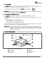
1
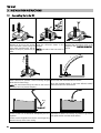
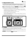
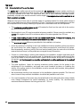
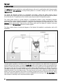
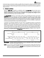
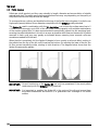
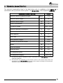
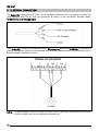
INSTALLATION AND OPERATING INSTRUCTIONS
¬ SPIDER KIT
CGM-04/392
ER-0170/1996
Thank you for choosing a DOMUSA product. From the range of DOMUSA
products you have chosen the Spider Kit. With suitable installation and
connected to a pellet boiler, this accessory will provide the ideal level of
comfort for your home.
This manual forms an essential part of the product and it must be
supplied to the user. Read the warnings and recommendations in the
manual carefully, as they contain important information on the safety, use
and maintenance of the installation.
This accessory must be installed by qualified personnel only, in
accordance with current legislation and following the manufacturer’s
instructions.
Start-up of these products and any maintenance operations must only be
carried out by DOMUSA Official Technical Assistance Services.
Incorrect installation of this appliance could result in injury or damage to
people, animals or property, and the manufacturer will hold no liability in
such cases.
CONTENTS
Page
1
SAFETY WARNINGS .....................................................................................................................................................2
2
LIST OF COMPONENTS...............................................................................................................................................3
3
INSTALLATION INSTRUCTIONS ...............................................................................................................................4
4
OPERATION ....................................................................................................................................................................8
5
TECHNICAL CHARACTERISTICS............................................................................................................................ 11
6
ELECTRICAL CONNECTION .................................................................................................................................... 12
1.1
1.2
3.1
3.2
3.3
3.4
4.1
4.2
FUEL WARNINGS .......................................................................................................................................................................... 3
ASSEMBLY AND INSTALLATION WARNINGS ............................................................................................................................... 3
ASSEMBLING THE SPIDER KIT ..................................................................................................................................................... 4
DIMENSIONAL CHARACTERISTICS OF THE MAIN SILO ............................................................................................................... 5
FILLING THE SILO ......................................................................................................................................................................... 5
CHARACTERISTICS OF THE SUCTION HOSE................................................................................................................................. 6
OPTIMUM CYCLE TIMES............................................................................................................................................................... 9
PELLET REMOVAL.......................................................................................................................................................................10
1
Spider
1
SAFETY WARNINGS
Carefully read this instruction manual and keep it in a safe, easily-accessible place. DOMUSA will not
be liable for any damages caused by failure to follow these instructions.
To guarantee optimum functioning of this kit and a long lifetime, the installation and maintenance
must be carried out by qualified personnel authorised by DOMUSA. The installer is responsible for any
devices or controls not supplied with the kit.
This appliance must only be used for the purpose for which it has been expressly designed. Any other
use is considered unsuitable and therefore hazardous. The manufacturer shall not be considered liable
under any circumstances for damage caused by unsuitable, erroneous or irrational use.
The Spider Kit is specifically designed for extracting 6 mm diameter pellets from a main silo and, in
combination with a pneumatic “Kit Aspiration” system, conveying them to a Bioclass boiler reserve
tank.
During installation or before any servicing, the following indications must be observed to prevent
personal injury or material damage:
• Remove all the packaging and check all the contents are included. In the event of any doubt, do
not use the kit. Contact your supplier. Keep the packaging elements out of reach of children, as
they can be dangerous.
• Unplug the Spider Kit from the mains power supply before any servicing and during installation.
• For safety reasons, another person should always be present when you access the pellet store. If
access to the store is difficult, we recommend a second person waits outside to guarantee the
safety of the person entering the store, and who can let them out in case of hazard without
endangering their own life.
• Before entering the pellet store, ensure it is correctly ventilated (there may be a lack of oxygen or
concentration of unknown gases).
• Always wear a protective mask (standard mask) inside the pellet store for protection from
airborne dust.
• Keep children away while you are working in the pellet store.
• If the pellet store is flooded there is no risk of contamination of the groundwater, the soil and/or
the building, although the tank and pellet removal system could be damaged.
• When you no longer wish to use this kit, disable all parts that could be a potential source of
hazard.
2
1.1
Fuel warnings
The Spider Kit is exclusively designed and intended to be used for pneumatic removal of wood
pellets with a diameter of 6 mm and a maximum length of 30 mm.
The wood pellets used must comply with the DINplus quality standard.
IMPORTANT: The pellets are highly hygroscopic. In case of contact with water or damp walls, they
will swell and rot and will be unfit for use.
1.2
Assembly and installation warnings
The Spider Kit must only be installed by authorised sufficiently qualified personnel.
The following regulations and guidelines must be complied with for assembly and use of heating
installations:
• Legal regulations on accident prevention.
• Legal regulations on environmental protection.
• Professional association standards for the sector.
As regards assembly and use of this kit, the standards and stipulations applicable in the particular
country and/or region in which it is installed must be observed.
IMPORTANT: The plastic pellet conveyor hose must be earthed to prevent any danger of the silo
catching fire due to sparks generated by accumulation of electrostatic charge
during the Spider kit’s functioning causing combustion and/or possible
deflagration of the pellets.
2
LIST OF COMPONENTS
3
8
4
2
5
1
6
7
1.
2.
3.
4.
Suction hose connection socket.
Motor casing.
Power cord.
Fixed plate.
5.
6.
7.
8.
Rotary plate.
Springs.
Earth connection.
Grip ring
3
Spider
3
INSTALLATION INSTRUCTIONS
3.1
Assembling the Spider Kit
Fit the hose with an interior
diameter of 50 mm to the suction
hose connection socket using the
hose clamp supplied with the kit.
Tighten it firmly to prevent any air
leaks.
Earth the copper wire on the hose Electrically connect the motor,
using the connector shown in the following the instructions given in the
diagram
diagram in the “Electrical connection”
section.
NOTE: Both ends of the hose must be
earthed.
10 cm
L
Attach the electrical cable to the suction hose using Adjust the length of the suction hose to ensure the Spider
plastic cable ties to prevent it from becoming tangled Kit can reach the areas furthest from the silo.
while the kit is functioning.
When the required length (L) has been defined, suitably
NOTE: We recommend fixing the cable to the hose at fasten the hose to the silo structure.
intervals of 10 cm to prevent tangling.
Ring
Fill the silo with pellets, keeping the Spider Kit outside Place the Spider Kit in the silo, on top of the pellets. It is
the silo so that it is not dented or damaged by the flow important to centre it as correctly as possible to guarantee
even pellet suction over the whole surface.
of pellets.
To take out the Kit Spider from the silo, use the grip ring
placed in the top of the motor casing.
4
3.2
Dimensional characteristics of the main silo
The main pellet silo must be constructed by sufficiently trained personnel and must comply with all
the national and regional regulations, standards and laws for this sector applicable at the time of
construction, particularly those referring to fire safety, boiler rooms and building safety.
For the Kit to function correctly, it must be connected to a pneumatic suction system. The Spider
Kit has been specially designed for connection to the Kit Aspiration system supplied by DOMUSA.
Construction of the main pellet silo must comply with the following size requirements for the
Spider Kit to function in combination with the Kit Aspiration system:
• The Spider Kit has been designed to cover a maximum circular area of 2 metres in diameter.
• The optimum silo size is a maximum of 2 x 2 metres. Providing it complies with these
dimensions, it may be square, rectangular or circular.
• The minimum permitted silo dimensions are 0.5 metres x 1 metre.
• A minimum height of 0.5 metres is recommended.
• There are no requirements with regard to maximum silo height, although it must be low
enough to allow for suitable filling.
If a silo larger than the above-mentioned sizes is required, we recommend constructing it with
tilted sides, as shown in the picture below.
2m
2m
3.3
Filling the silo
It is recommendable to remove the Spider Kit before filling and keep it outside the silo during the
filling process, to prevent it from being dented or damaged by the flow of pellets.
When the silo is full, stand the kit on the pellets again in the centre of the silo if possible, to ensure
uniform suction over the entire surface.
IMPORTANT: Correct functioning of the Spider Kit is only guaranteed if the wood pellets used as
fuel comply with the DINplus quality standard.
5
Spider
3.4
Characteristics of the suction hose
The Spider Kit for pellet removal and the pneumatic Kit Aspiration conveyor system, working in
combination, are specially designed to function with an installation consisting of a plastic hose with
an interior diameter of 50 mm. This hose must also have a static electricity discharge system,
preferably a copper wire wound around its entire length. This copper wire must be earthed at all
the hose joints and ends.
Whatever the type of hose used, it must be made of a suitable material for wood pellet transport
and it must always have an interior diameter of 50 mm. The following recommendations must also
be complied with for correctly installing the Spider Kit in combination with the Kit Aspiration:
• The maximum permitted hose length is 30 metres for flow from the main silo to the suction
pot and 30 metres for return.
• Bend angles of over 45º must be avoided wherever possible. If these cannot be avoided, any
curves with angles of over 45º must have a radius of curvature greater than 125 mm.
• If rigid plastic tubing is used, do not use standard 90º elbows. If these are necessary, the
curves constructed must have a minimum radius of 125 mm.
• The maximum height difference permitted for the installation is 6 metres.
• Avoid any splicing or coupling in the hose installation wherever possible, as this may narrow
the circuit which can cause clogging of the pellets conveyed and could block the system.
Most importantly, avoid any joints in the hose section leading from the main silo to the boiler
reserve tank suction pot, as the pellets are conveyed through this section.
• If there is no alternative to splicing and extending the installation, straight rigid tubing with
an interior diameter of 50 mm must be used. It is preferable for any splicing and joining of the
hose to be made in the pneumatic suction system return section, as only air is conveyed in
this section. All the hose sections must be earthed at all coupling points and at the ends of
the hose.
• The most significant factor for ensuring maximum suction power for the system is the
airtightness of the installation, and great care must therefore be taken on installing the
tubing. All coupling points in the installation must be secured with brackets, taking special
care to prevent leakage.
• We recommend avoiding hose crossover in the installation wherever possible. The flow and
return hoses of the pneumatic installation should be laid parallel to each other.
• For correct assembly of the hoses, they should be fixed to the walls and/or floor using suitable
hose clamps throughout the entire installation, to ensure stability. The recommended
maximum distance between the fixing points is 80 – 110 cm.
6
Some of the above recommendations are shown in the figure below:
KIT ASPIRATION
KIT SPIDER
MAIN SILO
RESERVE TANK
IMPORTANT: At each end of the pellet suction and air return hose, the copper cables must be
connected to the earth connection terminals provided for this purpose.
IMPORTANT: DOMUSA will hold no liability for any malfunctioning of the Spider Kit in
combination with the Kit Aspiration if the installation does not comply with the
above recommendations.
7
Spider
4 OPERATION
The Spider Kit removes pellets to a main pellet store or silo and, in combination with the pneumatic
suction system (Kit Aspiration), conveys these pellets to a smaller storage unit near the boiler
(Reserve Tank).
The Spider Kit basically consists of a pneumatic connection, where the pellet suction hose is
connected, and a motor that turns a mobile plate on the underside of the kit and removes the pellets
from the main silo. The pellets are then sucked up by the pneumatic Kit Aspiration system.
The rotary plate moves in circular fashion in symmetrical rotation cycles, alternating between
clockwise and counter-clockwise movement to prevent the hose from winding onto the kit. At the
same time, the suction system functions in cycles of a fixed duration to fill the suction pot in the
Bioclass boiler reserve tank. These suction pot filling cycles and the Spider Kit rotation cycles are
governed by the Kit Aspiration electronic control system.
The figure below shows a functional diagram of the Spider Kit installed in combination with a Kit
Aspiration:
General system operation is as follows: when the level sensor detects a low pellet level, the electronic
control starts up the suction unit and the Spider Kit motor, which begins to suck up the pellets from
the silo or main store and convey them to the suction pot in the upper part of the boiler reserve tank.
The suction unit runs for a set duration (a cycle), while it fills the suction pot. When the cycle is
complete, the suction unit stops and the hatch on the underside of the suction pot opens, emptying
the pellets inside it into the reserve tank. If the level sensor continues to detect no pellets when the
suction pot has been emptied, the suction unit starts up again and runs for another full cycle. When
the sensor detects pellets, the electronic control disables the functioning of the Kit Aspiration and
then remains on standby until it requires activation again.
8
If the level sensor continues to detect no pellets after 8 consecutive cycles, the electronic control
blocks the system functioning and the pilot light on the side of the control will come on to indicate a
system anomaly. To unblock the system, disconnect the electronic control from the mains supply and
then reconnect it.
4.1
Optimum cycle times
When the Spider Kit is installed in combination with the Kit Aspiration, the cycle time can be
adjusted using the adjustment screw on the side of the electronic control. This screw is used to
optimise the filling time for the suction pot in the upper part of the reserve tank, adapting it to the
different characteristics of each pneumatic installation. The adjustable time range is from a
minimum of 27 seconds per cycle to a maximum of 187.
The Kit Aspiration electronic control starts up each cycle by activating the suction unit and the
Spider Kit motor at the same time, turning the rotary plate and starting up the pellet suction
process from the main silo. When the cycle is complete, in order to prevent excess pellets
remaining in the hose installation and causing obstruction at the start of the next cycle, the control
stops the Spider Kit functioning 7 seconds before suction unit operation is disabled. This means the
suction unit continues taking in only the pellets that remain in the hose installation, emptying the
hose and preventing obstruction when the next cycle begins.
In general, we recommend adjusting the cycle time to its maximum setting, by turning the
adjustment screw clockwise as far as it will go. If the installation settings are causing the Kit
Aspiration to fill up some time before the end of each cycle, we recommend reducing the cycle
time for closer regulation, so that it coincides with each filling of the suction pot. It should also be
observed that the amount of pellets taken in on each cycle may vary considerably depending on
vacuum cleaner's filter maintenance, pellet quality and the main silo emptying level at any given
time, and it is therefore preferable to set long cycle times. The diagram below shows the
functioning cycles governed by the Kit Aspiration electronic control:
IMPORTANT: Thorough periodic maintenance of the Kit Aspiration’s filter is vital to ensure
sufficient uniform pellet suction flow.
NOTE: If you choose to install the Spider Kit with a control and suction system other than the Kit
Aspiration supplied by DOMUSA, we recommend adjusting its functioning to the cycle
types and times described above. DOMUSA does not guarantee correct functioning of the
kit if other cycle types and times are used.
9
Spider
4.2
Pellet removal
Pellets are a bulk product and they vary naturally in length, diameter and accumulation of volatile
material and dust. The pellet removal process described here may vary depending on the quality of
the pellets used and on the particular silo design.
To ensure optimum, uniform and durable functioning of the Spider removal system, it is vital to use
high quality wood pellets of 6 mm diameter, compliant with the DINplus quality standard.
The Spider Kit, used in combination with the Kit Aspiration, can cover a silo surface area of up to 2
x 2 metres and can empty up to 80% of the silo’s total volume capacity, with suitable maintenance
of the suction system filter. It is also recommended to periodically inspect the silo emptying level,
ensuring the pellet distribution in the silo is as even as possible at all times, as the amount of pellets
removed in each cycle may vary greatly as indicated above, meaning more removal cycles are
sometimes needed to fill the tank.
When the silo is completely full, the Spider Kit begins to form a cavity or a funnel effect, sucking in
the pellets from the top of the silo until it reaches the bottom. On reaching the base of the silo, the
kit then moves towards the sides, rotating in both directions. The diagram below shows how the
Spider Kit removes the pellets:
IMPORTANT: Correct functioning of the Spider Kit can only be guaranteed if the wood pellets
used comply with the DINplus quality standard.
IMPORTANT: It is important to position the Spider Kit in the centre of the silo and ensure there
are pellets underneath and around it, to guarantee even coverage of the entire
surface.
10
5
TECHNICAL CHARACTERISTICS
The technical characteristics listed in the table below refer to installation of the Spider Kit in
combination with a pneumatic suction system – the Kit Aspiration – both supplied by DOMUSA.
TECHNICAL CHARACTERISTICS
Maximum amount of pellets conveyed (*) (**)
VALUE
Kg/min.
3-6
Maximum suction length (*)
m
30
Maximum suction height (*)
m
6
mm
50
Connection voltage
-
230 V~ 50 Hz
Maximum electricity consumption
A
0.15
Maximum electric power
W
10
Motor capacitor
µF
1
Motor class
-
Class B
Motor protection degree
-
IP 40
Threaded joint protection degree
-
IP 60
Weight
Kg
5
Spider Kit diameter
mm
625
Spider Kit height
mm
230
ATEX equipment group
-
II
ATEX equipment category
-
300D T100
Suction hose diameter
(*)
This value only refers to installations made in combination with the Kit Aspiration optionally
supplied by DOMUSA.
(**) This value will vary depending on the amount of dirt on the vacuum clener's filter, the
maintenance of the Kit Aspiration pneumatic suction system, the length of the pneumatic
installation and the quality of the wood pellets.
11
Spider
6
ELECTRICAL CONNECTION
The Spider Kit is designed for a 230 V~, 50 Hz electrical connection. For it to function correctly, the
cable supplied with the kit must be connected as shown in the connection diagram below.
Remember to earth the appliance.
If the Spider Kit is installed in combination with a Kit Aspiration supplied by DOMUSA, the indications
given in the diagram below must be followed for correct electrical connection to the terminal strip of
the Kit Aspiration’s electronic control:
NOTE: The power supply must be connected so that the kit can be totally isolated and disconnected
in order to safely carry out any maintenance operations.
12
NOTES:
..............................................................................................................................................................................................................
..............................................................................................................................................................................................................
..............................................................................................................................................................................................................
..............................................................................................................................................................................................................
..............................................................................................................................................................................................................
..............................................................................................................................................................................................................
..............................................................................................................................................................................................................
..............................................................................................................................................................................................................
..............................................................................................................................................................................................................
..............................................................................................................................................................................................................
..............................................................................................................................................................................................................
..............................................................................................................................................................................................................
..............................................................................................................................................................................................................
..............................................................................................................................................................................................................
..............................................................................................................................................................................................................
..............................................................................................................................................................................................................
..............................................................................................................................................................................................................
..............................................................................................................................................................................................................
..............................................................................................................................................................................................................
..............................................................................................................................................................................................................
..............................................................................................................................................................................................................
..............................................................................................................................................................................................................
..............................................................................................................................................................................................................
..............................................................................................................................................................................................................
..............................................................................................................................................................................................................
..............................................................................................................................................................................................................
..............................................................................................................................................................................................................
..............................................................................................................................................................................................................
13
POSTAL ADDRESS
FACTORY AND OFFICES
Apartado 95
Bº San Esteban s/n
20730 AZPEITIA
20737 ERREZIL (Guipúzcoa)
Tel: (+34) 943 813 899
Fax: (+34) 943 815 666
www.domusa.es
DOMUSA reserves the right to make modifications of any kind to its product
characteristics without prior notice.
*CDOC000786*
CDOC000786
05/13