1
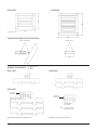
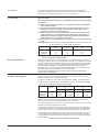
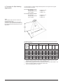
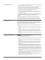
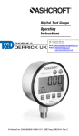
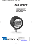
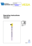
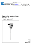
Installation and Operating Instructions
Models Covered:
Fax: +44 (0)191 477 5371
QXD1500
Email: [email protected]
QXD3000Website: www.heattracing.co.uk
www.thorneanderrick.co.uk
Tel: +44 (0)191 490 1547
QXD4500
IMPORTANT
08/50866/2 Issue 2
∗∗
These instructions should be read and carefully retained by the user.
∗∗
The installation of these appliances must always be carried out by a competent
electrician and be in accordance with the current wiring regulations and relevant
Building Regulations.
∗∗
The radiated heat from the heater is considerable and must be taken into account
when locating the heater. Ensure that the heater is not used in close proximity to
the skin or eyes.
∗∗
Always isolate the heater from the supply before undertaking any maintenance
work on the appliance.
∗∗
The QXD range of heaters are designed for internal use only. They are not rated as
flame-proof and must not be used when flammable dusts, gases, or vapours, etc.
are likely to be present in the atmosphere. If in doubt, advice should be sought
from the Health and Safety Executive inspectors or local fire officers.
∗∗
Quartz lamps are extremely fragile and must be handled with extreme care at all
times. Avoid touching the surface of the quartz sleeve with bare fingers. If the
sleeve is accidentally touched remove the finger print with a soft cloth moistened
with methylated spirits.
∗∗
This heater must not be located immediately above or below a fixed socket outlet
or connection box.
∗∗
The life expectancy of the halogen lamps in normal operating conditions is over
3000 hours.
∗∗
The heater must be installed in a location that is free from vibration.
WARNING – THIS APPLIANCE MUST BE EARTHED.
SPECIFICATIONS
The Dimplex QXD range is available in 1,2 and 3 lamp models with outputs of 1.5kW,
3.0kW and 4.5kW respectively. The three lamp models are supplied as dual voltage units
and are suitable for use on 230-240V and 415V 3N supplies.
General Data:
Model No.
No. of Lamps
Rating
(kW)
Voltage
(V)
Weight
(kg)
QXD1500
QXD3000
QXD4500
1
2
3
1.5
3.0
4.5
230-240
230-240
230-240
3.7
4.3
5.8
Material and Finished
Body Casing – Low carbon steel, powder coated.
Reflectors – 1080 (SIA) 99.8% Alum. Electrochemically brightened specular finish.
DIMENSIONS
QXD1500/1500ND/1500G
All dimensions in mm
QXD3000
QXD4500
All dimensions in mm
UNIVERSAL BRACKET MOUNTING
4 FIXING HOLES
ANGLE ADJUSTMENTS
WIRING DIAGRAMS
QXD1500
G/Y = GREEN/YELLOW
R = RED
B = BLACK
QXD3000
QXD4500
LINKS MUST
BE FITTED
LINKS MUST
BE REMOVED
HEATER WIRING
AS OPPOSITE
CABLE A
LL MODELS 2.5MM2
SILICONE INSULATED
(a) External connections for 230/240V 1pH
(b) External connections for 415V 3N
1. Location
The siting of the heater(s) should be such as to allow an even and uninterrupted
distribution of radiation to the area(s) to be heated. Heaters are most effective when the
beam angle is inclined down at an angle of 30º to 45º to the vertical.
2. Mounting
IMPORTANT
When deciding upon the best location, consideration must be given to the following
requirements.
(a) Avoid structures liable to vibration, e.g. crane gantries, which could otherwise
adversely affect lamp life.
(b) The lamps are designed to operate within 5º of the horizontal plane. It is very
important to ensure that the heater is mounted horizontally, otherwise the
operating life of the lamp could be impaired.
(c) Allow a minimum of 0.5 metre clearance between the top of the heater and the
ceiling. (Dimension ‘C’ on the appliance rating label.) Allow a minimum of 1.5
metre clearance between the edge of heater and the adjacent wall facing that
edge. (Dimension ’B’ on the appliance rating label.)
(d) Ensure appliance is mounted the correct way up so that it can be tilted down but
not up.
Mounting height: Allow the following mounting height between the base of the heater and
the floor. (Dimension ‘A’ on the appliance rating label.)
Model No.
Rating
(kW)
Min. Height
(m)
Recommended Height
(m)
QXD1500
QXD3000
QXD4500
1.5
3.0
4.5
2.1
2.5
3.0
2.5
2.5-3.5
3.5
Note: If more than one heater is to be installed, ensure that the lamps of adjacent
heaters are more than 3.5 metres apart.
Mounting Brackets
Heaters are supplied with a universal bracket which may be fixed through the mounting
holes to any suitable structure. The bracket allows the heater to be inclined to the required
angle from the vertical and permits the heater to be swivelled laterally. It is recommended
that when inclined from the vertical and swivelled care is taken to ensure that the lamps
are still horizontal. WARNING – THESE HEATERS ARE DESIGNED TO BE WALL
MOUNTED ONLY – THEY MUST NOT BE CEILING MOUNTED. THEY MUST NOT BE
MOUNTED IN A ROOM CONTAINING A BATH OR SHOWER.
DO NOT MOUNT HEATERS CLOSER THAN 3.5 METRES FROM CURTAINS OR
SIMILAR SOFT FURNISHINGS.
3. Electrical Supplies
Wiring to the heater must be installed in compliance with the requirement of the wiring
regulations and any local or insurance regulations.
All heaters are suitable for use on 230-240V single phase supplies. The 4.5kW model is
supplied as a dual voltage unit and is also suitable for use on 415V three phase supplies.
Heaters must be protected by fuses to the following rates:
Model No
Input Rating
(kW)
QXD1500
QXD3000
QXD4500
1.5
3.0
4.5
Current Rating
(A)
Fuse Rating
(A)
230-240V
415V
230-240V
415V
6.25
12.5
18.75
6.25/Ph
10
13
20
10/Ph
Wiring between the heater and the spur outlet or isolation switch must be in a heat
resisting cable (e.g. butyl rubber or high temperature PVC insulated). Sufficient slack
cable must be left to allow for angular adjustment of the heater body.
An all-pole isolating switch with a minimum separation of 3mm in each pole must be fitted
adjacent to the heater to facilitate local isolation.
If miniature circuit breakers are to be used, to avoid ‘nuisance tripping’ due to the high in
rush at switch on, a type 3 or ‘C’ rated MCB with a tripping coefficient of 7-10 times rated
current should be used. Any other switching device should be Tungsten lamp load rated.
4.5kW heaters must be connected in accordance with the instructions. When connecting
to 415V three phase supplies the links must be removed from the terminal block. When
using the heater on 230-240V supplies the “Danger 415V” notice should be removed from
the terminal cover.
* Always ensure that the cable grip is tightened. *
4. Coverage for Spot Heating
Applications
The area heated by a Quartz Halogen Heater depends on the height and the angle at
which the heater is mounted.
For 30° Heater Mounting Angle:
Area Covered Average Width of Beam Throw of Beam = (Height)² x 2.66
= Height x 2.0
= Height x 1.33
For 45° Heater Mounting Angle:
Area Covered Average Width of Beam Throw of Beam = (Height)² x 5.72
= Height x 2.2
= Height x 2.6
*Note:
Area covered, width and throw of beam are
measured at floor level.
The table below indicated throw and spread
measured 1 metre above floor level which may
be a more appropriate measurement for some
applications.
The following tables show the recommended mounting heights for three typical average
intensity requirements:
Average
Radiant
Intensity
on Heated
Area
(W/m²)
QXD1500
Height
(m)
Throw
(m)
QXD3000
QXD4500
Spread
(m)
Height
(m)
Throw
(m)
Spread
(m)
Height
(m)
Throw
(m)
Spread
(m)
Angled 30° from vertical
150
2.9
2.5
3.8
3.7
3.6
5.4
4.4
4.4
6.7
200
2.7
2.2
3.3
3.4
3.1
4.7
3.9
3.8
5.8
250
2.5
2.0
3.0
3.1
2.8
4.2
3.6
3.4
5.2
Angled 45° from vertical
150
2.3
3.4
2.9
2.9
4.9
4.2
3.3
5.6
5.0
200
2.1*
2.9
2.4
2.6*
4.1
3.5
3.0*
5.2
4.4
ote
N
1. Intensity is average intensity in W/m² based on Wattage of heater and area covered
and measured on a horizontal plane 1m above the floor level.
2. Heater mounting heights are in metres and are above floor level. Those marked ‘*’ are
minimum mounting heights for the particular heater model.
3. Throw and spread figures are in metres.
5. COMMISSIONING
1. Checks on the electrical installation should include earth continuity and insulation tests
and must be undertaken by a competent person.
2. Ensure that all the electrical connections at the lamps and the terminal rails have been
made correctly, that they are tight and that there is no loose or frayed wire.
3. Replace and secure the terminal cover and replace and secure the front panel.
4. Check that the mounting bracket is securely fixed in the vertical position such that the
lamps remain in a horizontal plane at all angles of heater displacement.
5. Roughly align the heater(s) and tighten the adjusters.
6. Switch on the heater(s) and check that the lamp(s) are all operating. If time or
temperature controls are fitted check these for correct and safe operation by reference
to the supplier’s instructions.
7. Make any adjustments that are necessary to give an even spread of heat over the
required area. This may be done simply by perception of the heating effect or by using
the distribution of visible light either at night or by darkening the room.
Hand over
Hand over these instructions and make sure the user is familiar with all aspects of
operation and safety including the need for regular cleaning and an annual inspection.
In the event of the premises being unoccupied then leave heater(s) switched off and
isolated from the electrical supply. Leave instructions adjacent to the electricity meter.
6. MAINTENANCE
Since the Dimplex Quartz Heater contains no moving parts little maintenance is required
beyond cleaning and lamp replacement. It is however, essential that the heater is not
operated with accumulation of dust or dirt on the lamp(s) or reflector(s) as this can cause
a build up of heat and eventual damage. For this reason the heater must be inspected
regularly depending upon conditions and at least at yearly intervals.
Before undertaking any maintenance work on the heater due attention must be paid to the
following:
1. Always disconnect the heater from the electricity supply before attempting to work on
or near it.
2. Always ensure a safe means of access using an access tower or properly supported
ladder.
3. Some types of quartz lamps run with an internal pressure in excess of atmospheric
pressure and while construction is very strong there is a slight risk of shattering. If it is
necessary to examine a bare lamp whilst in operation then a protective screen must
be used.
4. Allow adequate time for the lamps and body casing to cool before attempting to work
on the heater.
7. LAMP REPLACEMENT
WARNING. BEFORE UNDERTAKING THIS TASK ENSURE THE HEATER IS
DISCONNECTED FROM THE ELECTRICITY SUPPLY.
1. Detach heater from its mounting position.
2. Unscrew the front panel by loosening the corner fixing screws, and then lift front panel
clear.
3. Disconnect the wires to the old lamp by removing the lock nuts retaining the terminal
ends adjacent to the lamp clips. Do not slacken the screws as this could disturb the
internal wiring.
4. Remove the lamp by gently releasing the ends from the spring clips. Keep the lamp
secure and do not twist the ends or apply undue force. IMPORTANT - Release and
retain the high temperature cable ties from the element wires. (These must not be
substituted).
5. Before removing the new lamp(s) from its protective packing it is important to be
aware that quartz lamps are fragile and must be handled with care at all times. Avoid
touching the surface of the quartz sleeve with bare fingers. If the sleeve is accidentally
touched remove the finger print with a soft cloth moistened with methylated spirit.
6. Hold the lamp firmly but gently at each end and offer up to the spring mounting clips.
The wire leads should face towards the front of the heater. Push the lamp fully into the
clips taking care to keep it square. Do not twist the ends or apply undue force. If either
end of the lamp will not easily engage in the spring clips remove the lamp and gently
ease the spring.
7. The wire from each end of the lamp must be connected to the threaded connector ON
THE SAME CLIP AS THE LAMP END. With the outside not loosened, insert the spade
between the two outside nuts and tighten firmly.
8. When the lamp has been fitted check that the electrical connections have been
correctly made. Re-use the same cable tie to tether the element wires in place. Re-fit
the front panel, checking that wires are not trapped.
INSPECTION AND CLEANING
1. Check that all the lamps are functioning. If any thermostatic or time controls are fitted
ensure that the supply is ‘on’ before checking lamps. Any failed lamps should be
replaced (see lamp replacement). Remove any accumulated dirt and check wiring and
connections.
2. Clean the lamp(s) and reflector(s) using a mild detergent solution and soft cloth.
Do not use any abrasive or caustic cleaners. Dry with a soft cloth. Avoid touching
either, the quartz lamp sleeve or the aluminium reflector with bare fingers. If they
are accidentally touched remove any finger prints using a soft cloth moistened with
methylated spirit.
3. Check that the lamp(s) are properly located in the spring retaining clips and that they
have not been disturbed by cleaning. The lamps should be pushed fully back into the
clips for applying light pressure on the end caps only.
SAFETY IN OPERATION
The heater is operated by simply switching on the electrical supply, or, if used in
conjunction with a control system, then the supplier’s instructions must be observed.
ALWAYS disconnect the heater from the supply before attempting to work on or near it.
NEVER operate the heater with a high accumulation of dust or dirt on the lamp(s) or
reflector or with a damaged or corroded reflector.
This appliance is not intended for use by children or other persons without assistance
or supervision if their physical, sensory or mental capabilities prevent them from using it
safely. Children should be supervised to ensure they do not play with the appliance
NEVER use the heater outside or in contact with water.
NEVER use the heater where flammable dusts, gases or vapours, etc. are likely to be
present in the atmosphere.
NEVER operate the heater in close proximity to the skin or eyes.
NEVER allow materials which could be damaged or ignited by the radiated heat to be
placed in close proximity to the heater.
NEVER cover the heater – even when it is switched off.
ALWAYS refer to these instructions before attempting to dismantle the heater.
AFTER SALES SERVICE
Your Dimplex Quartz Heater is guaranteed for one year from the date of purchace. We
undertake to exchange or repair free of charge within this period, any part found to be
defective due to a manufacturing fault.
Should you require after sales service, please get in touch with the supplier through whom
you purchased the appliance, or the contact number on your Warranty leaflet.
Please do not initially return a faulty appliance or part of an appliance as this may result
in transit damage and/or delay in providing service. Let us know your difficulty quoting the
model number and series letter of the appliance. We will then take the appropriate action.
Tel: +44 (0)191 490 1547
Fax: +44 (0)191 477 5371
Email: [email protected]
Website: www.heattracing.co.uk
www.thorneanderrick.co.uk