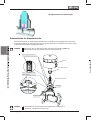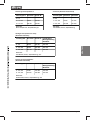
1
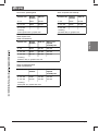
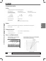
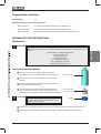
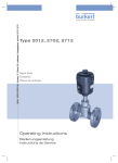
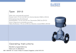
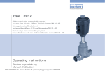
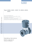
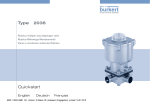
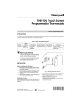
Type2012
Globe control valve, pneumatically operated
Actuator sizes 175 mm and 225 mm
Nominal diameters DN 65, DN 80, DN 100
Kolbengesteuertes Geradsitzventil
Antriebsgrößen 175 mm und 225 mm
Nennweiten DN 65, DN 80, DN 100
Soupape de réglage à tête droite commandée par piston
Tailles de mécanisme 175 mm et 225 mm
Diamètre nominal DN 65, DN 80, DN 100
Operating Instructions
Bedienungsanleitung
Instructions de Service
We reserve the right to make technical changes without notice.
Technische Änderungen vorbehalten.
Sous réserve de modifications techniques.
© 2000 - 2010 Bürkert Werke GmbH
Operating Instructions 1012/08_EU-ML_00804396 / Original DE
Piston controlled flat-seat valve
Actuator sizes 175 - 225 mm,
Nominal diameters DN 65, DN 80, DN 100
CONTENTS
Symbols ................................................................................................................................................................................................................................................... 2
Safety notes ....................................................................................................................................................................................................................................... 2
Scope of delivery ........................................................................................................................................................................................................................ 2
Warranty conditions ............................................................................................................................................................................................................... 2
TECHNICAL DATA ................................................................................................................................................................................................................................. 3
Construction ...................................................................................................................................................................................................................................... 3
Media ............................................................................................................................................................................................................................................................ 3
Temperatur range ....................................................................................................................................................................................................................... 3
Control and medium pressure ................................................................................................................................................................................ 3
COMMISSIONING ................................................................................................................................................................................................................................... 4
Installation of the valve ..................................................................................................................................................................................................... 4
Pneumatic installation ........................................................................................................................................................................................................ 5
MAINTENANCE .......................................................................................................................................................................................................................................... 5
Replacement of the valve seat ................................................................................................................................................................................ 5
Spare parts sets for standard valves ............................................................................................................................................................ 5
2012 big - 1
english
GENERAL NOTES ................................................................................................................................................................................................................................. 2
GENERAL NOTES
Symbols
The following symbols are used in these operating instructions:
marks a work stept that you must carry out
english
ATTENTION!
NOTE
marks notes on whose no-observance your health or the functioning of the device will
be endangered.
marks important additional information, tips and recommendations.
Safety notes
Please observe the notes in these operating instructions together with the conditions of use and
permitted data that are specified in the data sheets of valve, in order that the device will function perfectly
and remain operable for a long time:
• Keep to standard engineering rules in planning the use of and oprating the device!
• Installation and maintenance work are only allowed by specialist personnel using suitable tools!
• Observe the current regulations on accident prevention and safety for electrical devices during
operation and maintenance of the device!
• Switch off the supply voltage in all cases before intervening in the system!
• Note that in systems under pressure, piping and valves may not be loosened!
• Take suitable precautions to prevent inadvertent operation or damage by unauthorized action!
• On non-observance of these notes and unauthorized interference with the device, we will refuse all
liability and the warranty on device and accessories will become void!
Scope of delivery
Immediately after receipt of a shipment, make sure that the contents are undamaged and match the
scope of delivery stated ont he packing slip. If there are discrepancies, please contact immediately your
Bürkert subsidiary or our customer service:
Bürkert Fluid Control Systems
Service Department
Chr.-Bürkert-Str. 13-17
D-74653 Ingelfingen
Tel.: +49 (0)7940 / 10 91 111
Fax: +49 (0)7940 / 10 91 448
E-Mail: [email protected]
Warranty conditions
This document contains no warranty statements. In this connection we refer to our general sales and
business conditions. A prerequisite for validity of the warranty is use of the device as intended with
observance of the specified conditions of use.
ATTENTION!
2 - 2012 big
The warranty covers only faultless condition of valve Type 2012. No liability will be
accepted for consequent damage of any kind that may arise form failure or
malfunctioning of the device.
TECHNICAL DATA
Construction
2/2-way piston controlled valve with flat-seat housing
Control function B
(open in rest position)
Control function I
(double-acting actuator)
Actuator material
PA
Housing material
stainless steel 316L
Seal materials
PTFE
NBR, FKM and EPDM on request
english
Control function A
(closed by spring force
in rest position)
Media
Liquid and gaseous media that do not attack the housing and seal materials.
Control medium:
air
Temperatur range
Medium temperature:
-10°C to 180°C, with PTFE seal
Ambient temperature:
-10°C to 50°C
Control and medium pressures
Actuator diameter
225
PPilot / PMedium [bar]
65
4,5 / 0 - 16
-
80
4,5 / 0 - 10
3,3 / 0 - 16
100
4,5 / 0 - 7
4,8 / 0 - 16
16
Medium pressure [bar]
175
DN
DN 80
Control function B and I (only drive size
175), input flow under seating
DN 65
Control function A, input flow
under seating (standard)
DN 100
14
12
10
8
6
4
2
0
0
1
2
3
4
5
6
Control pressure [bar]
ATTENTION!
The max. permissible control pressure is 6 bar.
2012 big - 3
COMMISSIONING
english
Installation of the valve
Installation in any position, but preferably with the actuator above.
Observe the flow direction!
Clean piping form contamination!
Before attaching the valve housing, make sure the piping is
aligned!
If the housing is to be welded on, make absolutely sure that the
actuator is removed beforehand.
Procedure:
1. Remove the pneumatic supply and the elctrical connection
(if a pilot valve is attached).
2. Control function A: Pressurize the lower control
connection of the actuator with compressed air (6 bar), so
that the valve disk is lifted from the valve seat and is not
damaged.
Control functions B and I: With control functions B and I,
no compressed air must be applied for this purpose.
3. Remove the actuator int he open valve position by
unscrewing the threaded nipple (SW70) from the housing.
ATTENTION!
lower
control port
actuator
screw
(SW65)
threaded nipple
(SW70)
housing
Do not unscrew the screw /SW65) above the threeaded nipple.
4. Before reinstalling the actuator (in the open valve position), grease the nipple thread with stainless
steel lubricant, e.g. Klüberpaste UH1 96-402 from Messers. Klüber and replace the graphite seal if
necessary.
ATTENTION!
For special application such as for oxygen and analysis, use only the approved
lubricants.
5. Aligning the actuator:
After tightening the housing nipple (SW70) (observe torque), the actuator can be aligned as
required.
For this purpose, unsccrew the screw (SW65) above the threaded nipple ca. a halfthen retighten
the screw with a torque of 100 ±5 Nm.
ATTENTION!
During this operation, the valve must also be in the open position.
Tightening torques for the threaded nipple (SW 70)
DN
Tightening torque
[Nm]
NOTE
4 - 2012 big
65
80
100
100 ± 5
120 ± 5
150 ± 5
For applications in aggressive media, we recommend attaching all free pneumatic
connections to a pneumatic hose whose other end lies in a neutral atmosphere.
Pneumatic installation
air
Control medium:
Direct connection to the piston control valve
- control function A:
at the lower connection of the actuator with G ¼“ thread
- control function B:
at the upper connection of the actuator with G ¼“ thread
- control function I:
at the upper and lower connections of the actuator with G ¼“ thread
MAINTENANCE
ATTENTION!
english
Repairs
Repairs to the actuator may only be carried out in the factory.
Contact your Bürkert branch or our Customer Service:
Bürkert Fluid Control Systems
Chr.-Bürkert-Str. 13-17
Service Department
D-74653 Ingelfingen
Tel.: +49 (0)7940 / 10 91 111
Fax: +49 (0)7940 / 10 91 448
E-mail: [email protected]
Replacing the valve seat
Unscrew the old housing seat unsing the special tool and
a screwdriver.
Special tool
Clean the tread and sealing surface inthe housing with
compressed air.
Select the correct tool insert and screw it into the tool.
Push the new seat onto the tool, lubricate the thread with
high temperature resistant lubricant, e.g. Klüberpaste
UH1 96-402 from Messrs. Klüber.
ATTENTION!
Tool insert
(to match seat size)
Valve seat
For special applications such as for oxygen and
analysis, use only the approved lubricants.
Place the attached seat by hand in the housing thread and screw it in.
Tighten to the specified torque using a torque wrench.
2012 big - 5
english
Tightenning torques for seat assembly
Spare parts sets for standard valves
Spare parts availbable are a set of seals (packed gland), a valve set, a valve set plus seat and a set of
seals (pendulum disk). For disassembly of the actuator from the housing, one must proceed as described
under the item Installation.
NOTE
Before removal or opening of the device, always interrupt the supply of medium and relieve
the pressure in the piping.
set of seals, packed gland
actuator
screw SW 65
set of seals, pendulum disk
(DN80; DN100)
threaded nipple SW 70
valve set
Valve set plus
seat
NOTE
6 - 2012 big
Spare parts sets for special versions are available on request (e.g. oxygen or analysis
versions, etc.)
Set of seals, packed gland
Valve set (PTFE seal material)
Actuator size
Nominal
diameter
Order no.
Actuator size
Nominal
diameter
Order no.
∅ 175
DN 65
155 483
∅ 175
DN 65
155 491
∅ 175, 225
DN 80
155 484
∅ 175, 225
DN 80
155 492
∅ 175, 225
DN 100
155 485
∅ 175, 225
DN 100
155 493
containing:
packed gland module, graphite seals
containing:
pendulum disk, pin, graphite seal
Actuator size
Nominal
diameter
Order no.
Order no. of
required
assembly tool
∅ 175
DN 65
155 487
655 562
∅ 175, 225
DN 80
155 488
655 563
∅ 175, 225
DN 100
155 489
655 564
english
Valve set plus seat
(PTFE seal material)
containing:
pendulum disk, pin, graphite seal, seat
Valve set, pendulum disk
(PTFE seal material)
Actuator size
Nominal
diameter
Order no.
Order no. of
required
assembly tool
∅ 175, 225
DN 80
155 494
679 207
∅ 175, 225
DN 100
155 495
679 207
containing:
sealing disk, pin, graphite seal, seat
2012 big - 7
english
NOTES:
8 - 2012 big
Kolbengesteuertes Geradsitzventil
Antriebsgrößen 175 und 225 mm,
Nennweiten DN 65, DN 80, DN 100
INHALT:
ALLGEMEINE HINWEISE ...................................................................................................................................................................................................... 10
Darstellungsmittel .................................................................................................................................................................................................................. 10
Lieferumfang .................................................................................................................................................................................................................................. 10
Garantiebestimmungen .................................................................................................................................................................................................. 10
TECHNISCHE DATEN .................................................................................................................................................................................................................. 11
Aufbau ..................................................................................................................................................................................................................................................... 11
Medien ..................................................................................................................................................................................................................................................... 11
Temperaturbereich ................................................................................................................................................................................................................ 11
Steuer- und Mediumsdruck ...................................................................................................................................................................................... 11
INBETRIEBNAHME .......................................................................................................................................................................................................................... 12
Einbau des Ventils .................................................................................................................................................................................................................. 12
Pneumatische Installation .......................................................................................................................................................................................... 13
INSTANDHALTUNG UND WARTUNG ................................................................................................................................................................ 13
Reparaturen ..................................................................................................................................................................................................................................... 13
Austausch des Ventilsitzes ....................................................................................................................................................................................... 13
Ersatzteilsätze für Standardventile ............................................................................................................................................................... 14
2012 big - 9
deutsch
Sicherheitshinweise ............................................................................................................................................................................................................ 10
ALLGEMEINE HINWEISE
Darstellungsmittel
In dieser Betriebsanleitung werden folgende Darstellungsmittel verwendet:
markiert einen Arbeitsschritt, den Sie ausführen müssen
ACHTUNG!
HINWEIS
kennzeichnet Hinweise, bei deren Nichtbeachtung Ihre Gesundheit oder die Funktionsfähigkeit des Gerätes gefährdet ist
kennzeichnet wichtige Zusatzinformationen, Tipps und Empfehlungen
Sicherheitshinweise
deutsch
Bitte beachten Sie die Hinweise dieser Betriebsanleitung sowie die Einsatzbedingungen und zulässigen
Daten, die in den Datenblättern des Ventils spezifiziert sind, damit das Gerät einwandfrei funktioniert
und lange einsatzfähig bleibt:
• Halten Sie sich bei der Einsatzplanung und dem Betrieb des Gerätes an die allgemeinen Regeln der
Technik!
• Installation und Wartungsarbeiten dürfen nur durch Fachpersonal und mit geeignetem Werkzeug
erfolgen!
• Beachten Sie die geltenden Unfallverhütungs- und Sicherheitsbestimmungen während des Betriebes
und der Wartung des Gerätes!
• Schalten Sie vor Eingriffen in das System in jedem Fall die Spannung ab!
• Beachten Sie, dass in Systemen, die unter Druck stehen, Leitungen und Ventile nicht gelöst werden
dürfen!
• Treffen Sie geeignete Maßnahmen, um unbeabsichtigtes Betätigen oder unzulässige Beeinträchtigung
auszuschließen!
• Bei Nichtbeachtung dieser Hinweise und unzulässigen Eingriffen in das Gerät entfällt jegliche Haftung
unsererseits, ebenso erlischt die Garantie auf Geräte und Zubehörteile!
Lieferumfang
Überzeugen Sie sich unmittelbar nach Erhalt der Sendung, dass der Inhalt nicht beschädigt ist und mit
dem auf dem beigelegten Packzettel angegebenen Lieferumfang übereinstimmt. Bei Unstimmigkeiten
wenden Sie sich bitte umgehend an Ihre Bürkert-Niederlassung oder an unseren Kundenservice:
Bürkert Steuer- und Regelungstechnik
Service-Abteilung
Chr.-Bürkert-Str. 13-17
D-74653 Ingelfingen
Tel.: +49 (0) 7940 / 10 91 111
Fax: +49 (0)7940 / 10 91 448
E-Mail: [email protected]
Garantiebestimmungen
Diese Druckschrift enthält keine Garantiezusagen. Wir verweisen hierzu auf unsere allgemeinen Verkaufs- und Geschäftsbedingungen. Voraussetzung für die Garantie ist der bestimmungsgemäße Gebrauch des Gerätes unter Beachtung der spezifizierten Einsatzbedingungen.
ACHTUNG!
10 - 2012 big
Die Gewährleistung erstreckt sich nur auf die Fehlerfreiheit des Ventils Typ 2012. Es
wird jedoch keine Haftung übernommen für Folgeschäden jeglicher Art, die durch Ausfall oder Fehlfunktion des Gerätes entstehen könnten.
TECHNISCHE DATEN
Aufbau
2/2-Wege-Kolbensteuerventil mit Geradsitzgehäuse
Steuerfunktion A
(in Ruhestellung durch
Federkraft geschlossen)
Steuerfunktion B
(in Ruhestellung geöffnet)
Steuerfunktion I
(doppelt wirkender Antrieb)
Antriebswerkstoff
PA
Gehäusewerkstoff
Edelstahl 316L
Dichtwerkstoffe
PTFE
NBR, FKM und EPDM auf Anfrage
deutsch
Medien
Flüssige u. gasförmige Medien, die den Gehäuse- und Dichtwerkstoff nicht angreifen.
Steuermedium
Luft
Temperaturbereich
Medientemperatur
-10°C bis 180°C, bei PTFE-Dichtung
Umgebungstemperatur
-10°C bis 50°C
Steuer- und Mediumsdruck
Steuerfunktion A, Anströmung
unter Sitz (Standard)
Steuerfunktion B und I (nur Antriebsgröße
175), Anströmung unter Sitz
Antriebsdurchmesser
175
DN
225
PPilot / PMedium [bar]
65
4,5 / 0 - 16
-
80
4,5 / 0 - 10
3,3 / 0 - 16
100
4,5 / 0 - 7
4,8 / 0 - 16
ACHTUNG!
Der max. zulässige Steuerdruck beträgt 6 bar.
2012 big - 11
INBETRIEBNAHME
Einbau des Ventils
deutsch
Einbaulage beliebig, bevorzugt Antrieb nach oben.
Beachten Sie die Durchflußrichtung!
Säubern Sie die Rohrleitungen von Verunreinigungen!
Achten Sie vor Anschluß des Ventilgehäuses auf fluchtende
Rohrleitungen!
Entfernen Sie bei Schweißgehäusen den Antrieb unbedingt vor
dem Einschweißen des Gehäuses.
Vorgehensweise:
1. Entfernen Sie die pneumatische Versorgung und den
elektrischen Anschluss (bei angebautem Vorsteuerventil).
2. Steuerfunktion A: Beaufschlagen Sie den unteren Steueranschluß des Antriebes mit Druckluft (6 bar), damit der
Ventilteller vom Ventilsitz abhebt und nicht beschädigt wird.
Steuerfunktion B und I: Bei Steuerfunktion B und I muß
hierzu keine Druckluft angelegt werden.
3. Entfernen Sie den Antrieb in offener Ventilstellung durch
Losschrauben des Gewindenippels (SW70) vom Gehäuse.
ACHTUNG!
unterer
Steueranschluss
Antrieb
Schraube
(SW65)
Gewindenippel
(SW70)
Gehäuse
Lösen Sie nicht die Schraube (SW65) oberhalb des Gewindenippels
4. Fetten Sie vor Wiedereinbau des Antriebes (in offener Ventilstellung) das Nippelgewinde mit
Edelstahlschmierstoff ein, z.B. Klüberpaste UH1 96 - 402 der Firma Klüber, und erneuern Sie bei
Bedarf die Graphitdichtung.
ACHTUNG!
Verwenden Sie bei spezifischen Anwendungen, z.B. Sauerstoff-, Analyseanwendungen
nur zugelassene Schmierstoffe.
5. Ausrichten des Antriebs:
Nach dem Festziehen des Gewindenippels (SW70) (Drehmomente beachten) kann der Antrieb bei
Bedarf ausgerichtet werden.
Hierfür lösen Sie die Schraube (SW65) oberhalb des Gewindenippels ca. eine halbe Drehung und
bringen dann den Antrieb in die gewünschte Position.
Ziehen Sie danach die Schraube wieder mit 100 ± 5 Nm an.
ACHTUNG!
Das Ventil muss sich hierzu ebenfalls in der geöffneten Stellung befinden.
Anzugsmomente für den Gewindenippel (SW 70)
DN
Anzugsmoment
[Nm]
HINWEIS
12 - 2012 big
65
80
100
100 ± 5
120 ± 5
150 ± 5
Bei Einsatz in aggressiver Umgebung empfehlen wir, sämtliche freien Pneumatikanschlüsse mit Hilfe eines Pneumatikschlauches in neutrale Atmosphäre abzuleiten.
Pneumatische Installation
Luft
Steuermedium
Direkter Anschluß an das Kolbensteuerventil
- Steuerfunkion A:
am unteren Anschluß des Antriebes mit Gewinde G ¼“
- Steuerfunktion B:
am oberen Anschluß des Antriebes mit Gewinde G ¼“
- Steuerfunktion I:
am oberen und unteren Anschluß des Antriebes mit Gewinde G ¼“
INSTANDHALTUNG UND WARTUNG
ACHTUNG!
Reparaturen am Antrieb dürfen nur im Werk durchgeführt werden.
Wenden Sie sich hierzu an Ihre Bürkert Niederlassung oder direkt an unseren Kundenservice:
Bürkert Steuer- und Regelungstechnik
Chr.-Bürkert-Str. 13-17
Service-Abteilung
D-74653 Ingelfingen
Tel.: +49 (0)7940 / 10 91 111
Fax: +49 (0)7940 / 10 91 448
E-Mail: [email protected]
Austausch des Ventilsitzes
Schrauben Sie den alten Gehäusesitz mit Hilfe des
Montagewerkzeuges und einem Schraubenschlüssel aus.
Montagewerkzeug
Säubern Sie Gewinde und Dichtfläche im Gehäuse mit
Preßluft.
Wählen Sie den Werkzeugeinsatz aus und schrauben Sie
ihn in das Montagewerkzeug ein.
Stecken Sie den neuen Sitz auf das Montagewerkzeug,
schmieren Sie das Gewinde mit hoch-temperaturfestem
Schmierstoff z.B. Klüberpaste UH1 96-402 der Firma Klüber.
ACHTUNG!
Verwenden Sie bei spezifischen Anwendungen,
z.B. Sauerstoff-, Analyseanwendungen nur zugelassene Schmierstoffe.
Werkzeugeinsatz
(je nach Sitznennweite)
Ventilsitz
Setzen Sie den aufgesteckten Sitz von Hand in das Gehäusegewinde und schrauben Sie ihn ein.
Ziehen Sie ihn mit Hilfe eines Drehmomentschlüssels auf das angegebene Drehmoment an.
2012 big - 13
deutsch
Reparaturen
Anzugsmomente für Sitzmontage
Ersatzteilsätze für Standardventile
deutsch
Als Ersatzteile stehen ein Dichtungssatz Stopfbuchse, ein Ventilsatz, eine Ventilgarnitur und ein Dichtungssatz Pendelteller zur Verfügung. Zur Demontage des Antriebes vom Gehäuse muß wie unter dem
Punkt Einbau beschrieben vorgegangen werden.
HINWEIS
Unterbrechen Sie vor dem Ausbau oder dem Öffnen des Gerätes immer die
Mediumszufuhr und bauen Sie den Druck im Leitunssystem ab.
Dichtungssatz Stoffbuchse
Antrieb
Schraube SW 65
Dichtungssatz Pendelteller
(DN80; DN100)
Gewindenippel SW 70
Ventilsatz
Ventilgarnitur
HINWEIS
14 - 2012 big
Ersatzteilsätze für Sonderausführungen erhalten Sie auf Anfrage ( z.
B. Sauerstoff-, Analyseausfürungen usw.)
Dichtungssatz Stopfbuchse
Ventilsatz (Dichtwerkstoff PTFE)
Antriebsgrösse Nennweite Bestell.-Nr.
Antriebsgröße Nennweite Bestell-Nr.
∅ 175
DN 65
155 483
∅ 175
DN 65
155 491
∅ 175, 225
DN 80
155 484
∅ 175, 225
DN 80
155 492
∅ 175, 225
DN 100
155 485
∅ 175, 225
DN 100
155 493
Beinhaltet:
Pendelteller, Bolzen, Graphitdichtung
Beinhaltet:
Modul Stopfbuchse, Graphitdichtungen
Antriebsgröße
Nennweite Bestell-Nr. erforderliches
Montagewerkzeug
Bestell-Nr.
∅ 175
DN 65
155 487
655 562
∅ 175, 225
DN 80
155 488
655 563
∅ 175, 225
DN 100
155 489
655 564
deutsch
Ventilgarnitur (Ventilsatz + Sitz)
(Dichtwerkstoff PTF)
Beinhaltet:
Pendelteller, Bolzen, Graphitdichtung, Sitz
Dichtungssatz Pendelteller
(Dichtwerkstoff PTFE)
Antriebsgröße Nennweite Bestell-Nr. erforderliches
Montagewerkzeug
Bestell-Nr.
∅ 175, 225
DN 80
155 494
679 207
∅ 175, 225
DN 100
155 495
679 207
Beinhaltet:
Dichtscheibe, Bolzen, Graphitdichtung, Sitz
2012 big - 15
deutsch
NOTIZEN:
16 - 2012 big
Soupape à tête droite commandée par piston
Tailles de mécanisme 175 et 225 mm
Diamètre nominal DN 65, DN 80, DN 100
SOMAIRE:
REMARQUES GENERALES ............................................................................................................................................................................................. 18
Représentation ............................................................................................................................................................................................................................ 18
Consignes générales de sécurite .................................................................................................................................................................... 18
Fourniture ........................................................................................................................................................................................................................................... 18
CARACTERISTIQUES TECHNIQUES ................................................................................................................................................................ 19
Structure de la soupape ................................................................................................................................................................................................ 19
Fluides ..................................................................................................................................................................................................................................................... 19
Plage de température ........................................................................................................................................................................................................ 19
Pression de commande et de fluide ............................................................................................................................................................ 19
MISE EN SERVICE ............................................................................................................................................................................................................................ 20
Montage ................................................................................................................................................................................................................................................. 20
Installation pneumatique ............................................................................................................................................................................................. 21
MAINTENANCE ET ENTRETIEN ................................................................................................................................................................................ 21
Réparations ...................................................................................................................................................................................................................................... 21
Echange du siège de soupape ............................................................................................................................................................................. 21
Jeux de pièces de rechange pour soupapes standard .................................................................................................... 22
2012 big - 17
français
Clauses de garantie ............................................................................................................................................................................................................. 18
REMARQUES GENERALES
Symboles de représentation
Les symboles de représentation suivants sont utilisés dans cette notice de service:
marque une étape de travail devant être exécutée.
ATTENTION!
REMARQUE
caractérise des instructions dont l'inobservation entraîne des risques pour votre santé
ou met en cause la fonctionnalité de l'appareil
caractérise des informations supplémentaires importantes, des conseils et des
recommandations.
Consignes de sécurité
français
Veuillez tenir compte des consignes de cette notice de service de même que des conditions d'emploi et
données admissibles spécifiées dans les fiches techniques du TopControl ainsi que de la soupape à
méchanisme pneumatique correspondante afin que l'appareil fonctionne parfaitement et reste longtemps
opérationnel.
• S'en tenir aux règles techniques généralement reconnues lors du projet de mise en oeuvre et du
service de l'appareil.
• L'installation et les interventions nécessitées par la maintenance ne doivent être effectuées que par
un personnel qualifié équipé des outils adéquats.
• Respecter les dispositions en vigueur de prévention des accidents et de sécurité pour appareils
électrique pendant le service, la maintenance de l'appareil.
• Toujours couper la tension d'alimentation avant toute intervention dans le système.
• Tenir compte que dans le systèmes sous pression, les conduites et soupapes ne doivent pas être
desserrées.
• Pendre les mesures qui s'imposent pour éviter un actionnement par inadvertance de l'appareil ou une
mise en cause inadmissible de son fonctionnement.
• Assurer un redémarrage défini et contrôlé du processus après une interruption de l'alimentation
électrique ou pneumatique.
• En cas d'inobservation de ces consignes et d'interventions non autorisées dans l'appareil, nous
déclinons toute responsabilité de même qu'elles entraînent l'annulation de la garantie sur l'appateil et
les pièces accessoires!
Fourniture
Contrôler dès réception de l'envoi que le contenu n'a subi aucun dommage et qu'il correspond bien à la
fourniture figurant sur le bordereau d'envoi. En cas de non concordance, s'adresser immédiatement à
votre succursale Bürkert ou à notre service après vente
Bürkert Steuer- und Regelungstechnik
Service-Abteilung
Chr.-Bürkert-Str. 13-17
D-74653 Ingelfingen
Tel.: +49 (0)7940 / 10 91 111
Fax: +49 (0)7940 / 10 91 448
E-Mail: [email protected]
Clauses de garantie
Ce document ne constitue aucun assentiment de garantie. Nous vous renvoyons à cet effet à nos
conditions génerales de vente et commerciales. La condition préalable au consentement de la garantie
est l'utilisation conforme de l'appareil à l'usage auquel il est destiné, compte tenu de l'observation des
conditions d'emploi spécifiées.
ATTENTION!
18 - 2012 big
Les prestations de garantie ne s'étendent qu'à l'absence de défault de la soupape type
2012. Nous déclinons, par contre, toute responsabilité pour des dégâts consécutifs de
toute nature susceptibles de survenir par suite de défaillance ou défaut de
fonctionnement de l'appareil.
CARACTERISTIQUES TECHNIQUES
Structure
Soupape 2/2 voies commandée par piston à tête droite
Fonction de commande A
(fermée en position de repos par
effet de ressort)
Fonction de commande B
(ouverte en position de repos)
Fonction de commande I
(mécanisme à double effet)
Matière du mécanisme
PA
Matière du boîtier
Acier fin 316L
Matières étanches
PTFE
NBR, FKM et EPDM sur demande
Fluides
Fluides liquides ou gazeux qui n'attaquent pas la matière du boîtier et al matière étachne.
air
français
Fluide de commande:
Plage de température
Température des fluides
-10°C à 180°C, avec joint PTFE
Température ambiante
-10°C bis 50°C
Pression de commande et de fluide
Diamètre du mécanisme
225
PPilot / PMedium [bar]
65
4,5 / 0 - 16
-
80
4,5 / 0 - 10
3,3 / 0 - 16
100
4,5 / 0 - 7
4,8 / 0 - 16
16
Pression du fluide [bars]
175
DN
DN 80
Fonction de commande B et I (seulement
taille de mécanisme 175), afflux au dessous
du siège
DN 65
Fonction de commande A, afflux
au dessous du siège (standard)
14
DN 100
12
10
8
6
4
2
0
0
1
2
3
4
5
6
Pression de commande [bars]
ATTENTION!
La pression maximale de commande autorisée est de 6 bars!
2012 big - 19
MISE EN SERVICE
français
Montage de la soupape
Position de montage quelconque, de préférence, mécanisme vers
le haut.
Tenir compte du sens du débit!
Nettoyer les tuyauteries des impuretés!
Avant de raccorder le boîtier de la soupape, veiller à l'alignement
des conduites!
Enlever impérativement le mécanisme avant de souder le boîtier
dans le cas de boîtier à souder.
Manière de procéder:
1. Enlever l'alimentation pneumatique et le raccord électrique
(dans le cad de soupape pilote rapportée)
2. Fonction de commande A: Charger d'air comprimé (6 bars)
le raccord inférieur de commande du mécanisme afin que la
tête de soupape se soulève du siège et ne soit pas
endommagé.
Fonction de commande B et I: Aucun air comprimé ne doit
être chargé à cet effet
3. Enlever le mécanisme en position ouverte de la soupape, en
desserrant le raccord à vis (SW70) du boîtier.
ATTENTION!
Raccord inférieur
de commande
Mécansime
Vis
(SW65)
Raccord à vis
(SW70)
Boîtier
Ne pas desserrer la vis (SW65) au dessus du raccord à vis.
4. Avant de remoter le mécanisme (en position ouverte de la soupape), graisser le raccord à vis avec
un lubrifiant pour acier fin, p.ex. pâte Klüber UH1 96-402 de la maison Klüber, et renouveler le joint
graphite en cas de besoin.
ATTENTION!
Dans le cas d'applications spécifiques p.ex. applications d'analyse, d'oxygène, utiliser
uniquement des lubrifiants agrées.
5. Alignement du mécanisme:
Le mécanisme peut être aligné, si nécessaire, après avoir serré à fond le raccord à vis (SW70)
Veiller au couple de serrage)
A cet effet, desserrer la vis (SW65) au-dessus du raccord à vis d'environ un demi-tour et placer le
mécanisme dans la position souhaitée.
Resserrer ensuite la vis à 100 ± 5 Nm.
ATTENTION!
La soupape doit également se trouver à cet effet en position ouverte.
Couple de serrage pour le raccord à vis (SW 70)
DN
Couple de serrage
[Nm]
REMARQUE
20 - 2012 big
65
80
100
100 ± 5
120 ± 5
150 ± 5
En cas d'utilisation dans un environnement agressif, nous recommandons de dévier
tous les raccordements pneumatiques libres dans une atmosphère neutre à l'aide d'un
tuyau flexible pneumatique.
Installation pneumatique
Fluide de commande:
air
Raccord direct à la soupape commandée par piston
- fonction de commande A:
au raccord inférieur du mécanisme avec filet G ¼“
- fonction de commande B:
au raccord supérieur du mécanisme avec filet G ¼“
- fonction de commande I:
aux raccords supérieur et inférieur du mécanisme avec filet G ¼“
MAINTENANCE ET ENTRETIEN
ATTENTION!
Les réparations du mécanisme ne doivent être faites qu'en usine.
S'adresser à cet effet à votre succursale Bürkert ou directement à notre service
clientèle:
Bürkert Steuer- und Regelungstechnik
Chr.-Bürkert-Str. 13-17
Service-Abteilung
D-74653 Ingelfingen
Tel.: +49 (0)7940 / 10 91 111
Fax: +49 (0)7940 / 10 91 448
E-Mail: [email protected]
Echange du siège de soupape
Dévisser l'ancien siège de boîtier à l'aide de l'outil de
montage et d'une clé à vis.
Outil de montage
Nettoyer le pas de vis et la surface d'étanchéité dans le
boîtier à l'air comprimé.
Choisir l'embout d'outil et le visser dans l'outil de montage.
Mettre en place le nouveau siège sur l'outil de montage,
graisser le filetage avec un lubrifiant résistant aux
températures élevées p. ex pâte Klüber UH1 96-402 de la
maison Klüber.
ATTENTION!
Embout d'outil
(suivant diamètre nominal du siège)
Dans le cas d'applications spécifiques p.ex.
applications d'analyse, d'oxygène, utiliser
uniquement des lubrifiants agrées.
Siège de
soupape
Introduire le siège monté à la main dans le filet du boîtier et le visser.
Le serrer à l'aide d'une clé dynamométrique au couple indiqué.
2012 big - 21
français
Réparations
Couple de serrage pour le montage du siège
Jeux de pièces de rechange pour soupapes standard
Sont disponibles come pièces de rechange, un jeu de joints presse-étoupe, un jeu de soupapes, une
garniture de soupape et un jeu de garnitures tête de soupape oscillante. Pour démonter le mécanisme
du boîtier, il faut procéder comme décrit dans Montage.
REMARQUE
Avant de démonter ou ouvrir l'appareil, couper impérativement l'arrivée de fluide et
supprimer la pression dans le système de conduites.
français
Jeu de joints presse-étoupe
Mécanisme
Vis SW 65
Jeu de joints tête de soupape oscillante
(DN80; DN100)
Raccord à vis SW 70
Jeu de
soupape
Garniture de
soupape
REMARQUE
22 - 2012 big
Vous recevrez sur demande les jeux de pièces de rechange pour les versions spéciales
(p.ex. versions pour analyse, oxygène etc.)
Jeu de joints presse-ètoupe
Jeu de soupapes (matière étanche PTFE)
Taille de
mécanisme
Diamètre
nominal
No. de
commande
Taille de
mécanisme
Diamètre
nominal
No de
commande
∅ 175
DN 65
155 483
∅ 175
DN 65
155 491
∅ 175, 225
DN 80
155 484
∅ 175, 225
DN 80
155 492
∅ 175, 225
DN 100
155 485
∅ 175, 225
DN 100
155 493
Comporte:
module presse-étoupe, joints graphite
Comporte:
tête de soupape oscillante, axes, joint
graphite
Taille de
mécanisme
Diamètre
nominal
No de
Outil de montage
commande nécessaire
No de commande
∅ 175
DN 65
155 487
655 562
∅ 175, 225
DN 80
155 488
655 563
∅ 175, 225
DN 100
155 489
655 564
français
Garniture de soupape (jeu de soupapes+siège)
(matière étanche PTF)
Comporte:
Tête de soupape oscillante, axes, joint graphite, siège
Jeu de joints tête de soupape oscillante
(matière étanche PTFE)
Taille de
mécanisme
Diamètre
nominal
N° de
commande
Qutil de montage
nécessaire
N° de commande
∅ 175, 225
DN 80
155 494
679 207
∅ 175, 225
DN 100
155 495
679 207
Comporte:
Rondelle d'étanchéité, axes, joint graphite, siège
2012 big - 23
français
NOTICE:
24 - 2012 big
www.burkert.com