1
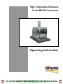
High Temperature Enclosure
for the MP150 Linescanner
Operating Instructions
Rev. B 01/2010
58601
i Tel: (01943) 602001- WWW.ISSLTD.CO.UK - Fax: (01943) 816796 i
WARRANTY The manufacturer warrants this instrument to be free from defects in material and workmanship under normal use and service for the period of two years from date of purchase. This warranty extends only to the original purchaser. This warranty shall not apply to fuses, batteries, or any product which has been subject to misuse, neglect, accident, or abnormal conditions of operation. In the event of failure of a product covered by this warranty, the manufacturer will repair the instrument when it is returned by the purchaser, freight prepaid, to an authorized Service Facility within the applicable warranty period, provided manufacturer’s examination discloses to its satisfaction that the product was defective. The manufacturer may, at its option, replace the product in lieu of repair. With regard to any covered product returned within the applicable warranty period, repairs or replacement will be made without charge and with return freight paid by the manufacturer, unless the failure was caused by misuse, neglect, accident, or abnormal conditions of operation or storage, in which case repairs will be billed at a reasonable cost. In such a case, an estimate will be submitted before work is started, if requested. THE FOREGOING WARRANTY IS IN LIEU OF ALL OTHER WARRANTIES, EXPRESSED OR ILIED, INCLUDING BUT NOT LIMITED TO ANY ILIED WARRANTY OF MERCHANTABILITY, FITNESS, OR ADEQUACY FOR ANY PARTICULAR PURPOSE OR USE. THE MANUFACTURER SHALL NOT BE LIABLE FOR ANY SPECIAL, INCIDENTAL OR CONSEQUENTIAL DAMAGES, WHETHER IN CONTRACT, TORT, OR OTHERWISE. Specifications subject to change without notice. T ABLE OF C ONTENTS 1 SAFETY INSTRUCTIONS..............................................................................................................................1
2 DESCRIPTION..................................................................................................................................................2
2.1.1 High Temperature Enclosure ................................................................................................................2
3 TECHNICAL DATA.........................................................................................................................................3
3.1 AMBIENT TEMPERATURE ..............................................................................................................................3
3.2 PRESSURE ......................................................................................................................................................3
3.3 WATER FLOW ...............................................................................................................................................4
3.4 AIR FLOW......................................................................................................................................................4
3.5 MATERIAL .....................................................................................................................................................4
3.6 WEIGHT ........................................................................................................................................................4
3.7 SCOPE OF DELIVERY .....................................................................................................................................5
3.8 DIMENSION ...................................................................................................................................................6
4 INSTALLATION ..............................................................................................................................................7
4.1 AMBIENT TEMPERATURE ..............................................................................................................................7
4.2 WATER ..........................................................................................................................................................7
4.3 AIR ................................................................................................................................................................7
4.4 PROCESS OPENING .......................................................................................................................................7
4.5 MOUNTING HOLES .......................................................................................................................................8
4.5.1 Enclosure, Standard ..............................................................................................................................8
4.5.2 Enclosure with External Shields ...........................................................................................................8
4.6 MOUNTING THE CABLE CONDUIT ...............................................................................................................8
4.7 MOUNTING THE SCANNER HANDLE ...........................................................................................................9
4.8 GROUNDING THE SCANNER .......................................................................................................................10
4.9 SYSTEM ASSEMBLY......................................................................................................................................10
4.10 INTEGRATED SHUTTER .............................................................................................................................11
4.11 SCANNER AIR PURGE ...............................................................................................................................11
5 OPTIONS .........................................................................................................................................................13
5.1 INTERNAL COLD PLATES ............................................................................................................................13
5.1.1 Connecting a Water Line ....................................................................................................................13
5.1.2 Replacing the Internal Cold Plates......................................................................................................13
5.1.3 Dimensions .........................................................................................................................................14
6 ACCESSORIES................................................................................................................................................15
6.1 EXTERNAL WATER COOLED SHIELD ..........................................................................................................15
6.1.1 Installation ..........................................................................................................................................15
6.1.2 Dimensions .........................................................................................................................................16
6.2 EXTERNAL INSULATING SHIELD.................................................................................................................17
6.2.1 Dimensions .........................................................................................................................................17
6.3 VORTEX COOLER ........................................................................................................................................18
6.3.1 Installation ..........................................................................................................................................18
6.3.2 Dimensions .........................................................................................................................................18
7 APPENDIX .......................................................................................................................................................19
7.1 ENCLOSURE WITH INTERNAL COLD PLATES .............................................................................................19
7.2 ENCLOSURE WITH VORTEX COOLER ......................................................................................................... 20
7.3 ENCLOSURE, FULLY DEVELOPED............................................................................................................... 21
Safety Instructions 1 Safety Instructions This document is part of the operating instructions for the Raytek MP150 linescanner. All tips and notices regarding acceptable operation and safety must be read in addition to the technical information. This document contains important information, which should be kept at all times with the instrument during its operational life. Other users of this instrument should be given these instructions with the instrument. Updates to this information must be added to the original document. The instrument can only be operated by trained personnel in accordance with these instructions and local safety regulations. Acceptable Operation This instrument is intended only as accessory for the Raytek infrared linescanner. The instrument operates reliably in demanding conditions, such as in high environmental temperatures, as long as the documented specifications are adhered to. Compliance with the operating instructions is necessary to ensure the expected results. Unacceptable Operation The instrument should not be used for other purposes. Replacement Parts and Accessories Use only original parts and accessories approved by the manufacturer. The use of other products can compromise the operational safety and functionality of the instrument. Instrument Disposal Disposal of old instruments should be handled according to professional and environmental regulations as electronic waste. Operating Instructions The following symbols are used to highlight essential safety information in the operation instructions: Helpful information regarding the optimal use of the instrument. Warnings concerning operation to avoid instrument damage. Warnings concerning operation to avoid personal injury. High Temperature Enclosure 1 Description
2 Description 2.1.1 High Temperature Enclosure The modular high temperature enclosure system is specifically designed to protect the linescanner from exposure to ambient temperature up to 1090°C (2000°F). While protected in this enclosure, the linescanner can operate comfortably in high temperature processes such as those seen in processing steel and other metals as well as glass and a variety of minerals. Base Plate
Figure 1: Standard Enclosure with Base Plate By design, the high temperature enclosure system is modular in nature. The standard enclosure, while insulated, provides only minimal heat resistance. Additional cooling elements include an external insulation plate, an external water plate, smaller internal water plates and a vortex cooler. Vortex Cooler
Connections for
Internal Cold Plates
External Water
Cooled Shield
External Insulating
Shield
Figure 2: Enclosure with Accessories The enclosure is fabricated from stainless steel and is lined with high performance refractory material for optimum heat resistance performance. The scanner is firmly held in place with four thermally isolated locating columns to facilitate aiming. The enclosure includes an opening for a 2” conduit (opening 60 mm / 2.36 in. diameter) which is the recommended means for conveying the power and communication cables to the enclosure. An integrated shutter shields scanner from process to facilitate removal for service or calibration. The shutter is actuated by an air cylinder. The system is designed in the “normally closed” position so that, in the event that air pressure is interrupted, the shutter will close to protect the scanner. The enclosure was designed with ergonomics in mind to facilitate installation, cabling and maintenance. No tools are required to remove the scanner and a handle is supplied to simplify removal of the scanner even when wearing heavy protective clothing. 2 High Temperature Enclosure
Technical Data 3 Technical Data 3.1 Ambient Temperature The ambient temperature specifies the maximum air temperature at the front plate/shield of the enclosure. Enclosure, Standard 50°C (122°F) Enclosure, Standard + Scanner with Air Purging 80°C (176°F) Enclosure + Vortex Cooler + External Insulating Shield 340°C (650°F) Enclosure + Vortex Cooler + External Water Cooled Shield 590°C (1100°F) Enclosure + Vortex Cooler + External Water Cooled Shield + External Insulating Shield 760°C (1400°F) Enclosure + Internal Cold Plates + Vortex Cooler + External Water Cooled Shield + External Insulating Shield 1090°C (2000°F) In all cases the internal temperature of the enclosure must be below the maximum ambient rating of the linescanner which is 50°C (122°F)! Vortex Cooler 93°C (200°F) Air Filter for Vortex Cooler 49°C (120°F) Oil Filter for Vortex Cooler 49°C (120°F) Conduit 600°C (1112°F) 3.2 Pressure Integrated Shutter 1.5 to 10 bar (22 to 145 PSI) Scanner Air Purge 1.5 to 3 bar (22 to 43.5 PSI) Internal Cold Plates 8.6 bar (125 PSI) External Water Cooled Shield max. 8 bar (116 PSI) Vortex Cooler 5.5 to 6.9 bar (80 to 100 PSI) High Temperature Enclosure 3 Technical Data
3.3 Water Flow Internal Cold Plates min. 1 l/min (0.26 gal/min) External Water Cooled Shield min. 7.6 l/min (2 gal/min) 3.4 Air Flow Scanner Air Purge 100 to 200 l/min (25 and 50 gal/min) Vortex Cooler 1132 l/min (300 gal/min) for heat dissipation of 820 W / 706 kcal/h (2800 Btu/hr) 3.5 Material Enclosure stainless steel 1.4301 (AISI 304) and refractory lining base plate: Aluminum AL 6061‐T6 or equivalent, coating: HART‐COAT® Conduit stainless steel hose: 1.4404 (AISI 316 L) braiding: 1.4301 (AISI 304) Internal Cold Plates Aluminum plates with stainless steel pipes External Water Cooled Shield stainless steel 1.4301 (AISI 304) External Insulating Shield stainless steel 1.4301 (AISI 304) packed with refractory Vortex Cooler stainless steel, type 316 3.6 Weight Linescanner, with air purge 7 kg (247 oz.) Enclosure, without linescanner 21 kg (740 oz.) Internal Cold Plates 1.5 kg (53 oz.) Vortex Cooler 2.3 kg (81 oz.) External Water Cooled Shield 12.4 kg (437 oz.) 4 High Temperature Enclosure
Technical Data External Insulating Shield 10.0 kg (352 oz.) 3.7 Scope of Delivery The enclosure package XXXSYSENC includes the following: • Stainless steel enclosure with base plate and mounting aperture for high performance vortex cooler •
Integrated fail‐safe shutter •
2” cable conduit, 1.5 m long (59 in.) High Temperature Enclosure 5 Technical Data
3.8 Dimension Cable and Air Supply through
High Temperature Enclosure
6 Air IN to Scanner Air Purge
Swagelok – ¼” OD tube
Air IN to Shutter
Swagelok – ¼” OD tube
Cover Plate – assembled, if enclosure
is supplied without Vortex Cooler
Figure 3: Dimensions for Standard Enclosure Installation 4 Installation 4.1 Ambient Temperature In many cases there is a very poor understanding of the actual temperatures at the site where the enclosure is mounted. While process temperatures are typically very well monitored and controlled, there is ambient conditions around the process have no bearing on product throughput or quality and therefore remain unknown. It is recommended to perform considerable testing. In a first step, the enclosure and the entire assembly but without the linescanner installed can be exposed to the expected ambient conditions. The external temperature needs to be measured at the surface. Temperature can be also recorded inside the enclosure at a number of points. 4.2 Water Cooling water will be required, if either the Internal Cold Plates or the External Water Cooled Shield are installed. Although the available cooling equipment is designed to tolerate typical plant cooling water cleanliness levels, as much as is possible, water should be clean and free from gross contaminants. Where concern exists, we recommend that a filter be installed and in all cases, water condition should be monitored periodically. 4.3 Air In general, air lines should be as straight as possible to minimize potential for flow constriction and potential blockage. Similarly, flow restricting fittings such as quick disconnects should be avoided as much as possible. We recommend an external self venting air valve to minimize pressure when uncoupling the linescanner. Air is always required for both the integrated shutter actuator and the air purge for the scanner itself. 4.4 Process Opening Before mounting the enclosure in an application, an opening will need to be fabricated so that the scanner can have a clear view of the process. If this opening is too large, an excessive amount of heat will reach the enclosure and the cooling systems may not have sufficient capacity to remove this heat. On the other hand, if the opening is too small, it may block the field of view between the scanner and the process and result in part of the process being shielded from the scanner during operation. For optimum performance we recommend an opening 381 mm (15”) long and 119 mm (4.7”) wide. Of course, to ensure that the scanner is properly oriented the shorter dimension should be in line with process flow. The scanner has a field of view of 90°. As such, the further the distance from the scanner mounting location, the wider the physical scan line becomes. When mounting the enclosure on surfaces where the wall of the process is very thick, perhaps due to large amounts of insulation, take care to ensure that the opening has sufficient angle so that it does not block the edges of the scanner field of view. High Temperature Enclosure 7 Installation
4.5 Mounting Holes 4.5.1 Enclosure, Standard Depending on the accessories selected there are a number of ways of mounting the enclosure to the process. In this modular system’s most simple configuration, only the enclosure and base plate will be provided. In this case, there are four through holes, 11 mm (7/16”) in diameter, located one on each corner of the base plate. In this case the base plate can be mounted with bolts or studs as desired. Recommended size of customers process opening. Recommended size of customers process opening (not scaled view)
Figure 4: Bottom View of the Enclosure’s Base Plate 4.5.2 Enclosure with External Shields If either the External Insulating Shield or the External Water Cooled Shield is installed, there will be a total of eight through holes which can be used to mount the assembly. In this case, the height of the assembly will increase by 32 mm (1.26 in.) if one shield is used or 64 mm (2.52 in.) if both are used. Take care to use fasteners with sufficient thread length to accommodate this assembly. For further details see Figure 9 Dimensions for the External Water Cooled Shield, on page 16. 4.6 Mounting the Cable Conduit The scanner will always require power and communication cable connections and in some circumstances an additional cable for alarm/trigger functions is also connected. 8 It is strongly recommended to use high temperature cables for the scanner only! The high temperature cables allow a maximum temperature of 180°C (356°F) but need to be ordered separately! High Temperature Enclosure
Installation It is recommended that the high temperature cables will be installed in the conduit. The enclosure is equipped with a large opening, 60.5 mm (2.38 in.) in diameter specifically for this purpose. To further facilitate installation, a 1.5 m (59 in.) stainless steel flexible conduit is supplied with the enclosure (other lengths on request). To assemble, insert the conduit through the opening taking care to ensure that the washer and the nut is on the inside of the enclosure. Washer and Nut Securing
Cable Conduit (view insight box)
Flexible Conduit
Stainless Steel
Figure 5: Conduit Connection 4.7 Mounting the Scanner Handle For ease of insertion and removal of the scanner from the enclosure, a mounting handle is provided. Before installing the scanner into the enclosure, attach the handle to the scanner with the four M3 x 20 fasteners provided. Grounding point
Handle
M3 Fasteners
Figure 6: Handle Assembly High Temperature Enclosure 9 Installation
4.8 Grounding the Scanner To ground the linescanner simply connect the yellow grounding cable to the M3 screw which fixes the blind caps on the back of the scanner (grounding point). To disconnect quickly the linescanner in the field pull out the quick connect pin at the grounding point. 4.9 System Assembly After the opening has been prepared in the process and the mounting studs or bolts have been installed, the enclosure and various cooling accessories should be assembled. In cases where the External Insulating Plate is use, this should always be located closest to the process. The cooling concept is that it is better to prevent the heat from reaching the enclosure by using the insulating plate than it is to try to remove it with either air or water. After mounting the External Insulating Shield and, if ordered, the External Water Shield, the Enclosure and base plate can be lowered onto the studs and the assembly completed with nuts and lock‐washers. Air supply for
air purging
Air supply for
shutter
Figure 7: Enclosure Air Connections Install the flexible stainless steel conduit provided with the enclosure into the conduit opening. Run the power, communication, and if required, trigger cables, leaving approximately 300 mm (12 in.) inside the enclosure for connection to the scanner at a later point in the process. At this point you will be ready to make the cooling water connections as necessary. External air connections can be made to the integrated shutter assembly and the scanner’s air purge. If the Vortex Cooler has been ordered, remove plates from the circular opening in the top of the enclosure and install the Vortex Cooler using the locknut provided. Connect the air as indicated in section 6.3 Vortex Cooler, on page 18. 10 Once all of the cooling facilities are connected, it is strongly recommended that you run the enclosure with all cooling options operational for one hour minimum to reduce the ambient air temperature within the enclosure! After this period, make the electrical and air purge connections to the scanner outside the enclosure and gently lower it into place using the handle provided! High Temperature Enclosure
Installation 4.10 Integrated Shutter The integrated shutter actuator is a pneumatic piston with a normal closed position. Compressed air (or nitrogen) at a pressure of 1.5 bar (22 PSI) is required to open the integrated shutter. External air supply connections are made to fittings on the outside of the enclosure. Looking at the rear of the enclosure, the shutter connection is located at the upper right corner see Figure 7 Enclosure Air Connections, on page 10. Factory air can be connected at this point with a typical 1/4” outer diameter tube. Internal connection to the shutter actuator is pre‐installed. We recommend an external self venting air valve for the purpose of closing the integrated shutter when the linescanner is being replaced. 4.11 Scanner Air Purge The scanner air purge is always required to keep dust and debris from settling on the lens and obscuring the field of view. Required airflow rates are between 200 to 400 l/min (50 and 100 gal/min). The maximum recommended pressure is 3 bar (43.5 PSI). External air supply connections are made to fittings on the outside of the enclosure. Looking at the rear of the enclosure, the air purge connection is located at left‐center, see Figure 7 Enclosure Air Connections, on page 10. Factory air can be connected at this point using a typical compression fitting sized for 1/4” outer diameter tube. Stainless steel braided hoses are provided for connection to the scanner to provide air for the air purge function. If you need to assemble the air‐hose to the scanner in the field, you need to do the following: 1. Disassemble the elbow‐ /T‐fitting. 2. Screw the straight connector into the ISO228 G1/8” (parallel thread‐ RS) of the air purge (2x) taking care to insert the stainless steel gasket for 1/8 in. in between. 3. Insert tubing with pre‐swaged ferrules into the fitting body until the ferrule seats; rotate the nut by hand to the pulled‐up position; tighten ¼ revolution with a wrench. Note the orientation of the Air hose assembly ‐ the T‐fitting will be in front of you. High Temperature Enclosure 11 Installation
To Couple:
Stem
Body sleeve
4. The Air supply hose can be connected to the Instrumentation Quick Connect at the enclosure wall. Align stem with
body. Push stem
into body until it
clicks.
To Uncouple:
Stem
Body sleeve
Pull body sleeve
toward stem.
12 High Temperature Enclosure
Options 5 Options Options are items that are factory installed and must be specified at time of order. The following are available: •
Internal Cold Plates (XXXSYSENCICP) 5.1 Internal Cold Plates A compact and cost‐effective solution where cooling needs are low to moderate, the Internal Cold Plates are aluminum plates with stainless steel tubing through which the cooling water flows. To provide optimum protection, the Internal Cold Plates are mounted directly adjacent to the scanner. Upon shipment, the water connections are all in place and connection to plant cooling water is made outside the enclosure. By this design, if a leak occurs the water will not enter the process through the viewing window. The ergonomic design permits rapid replacement in the event that the plates become fouled due to contaminated cooling water. 5.1.1 Connecting a Water Line The Internal Cold Plates are fabricated such that the piping extends through the wall of the enclosure itself. When the enclosure is viewed from the rear, four 3/8” stainless steel pipes can be clearly seen. Using 3/8” compression fittings connect the factory water supply and check for leaks. The Internal Cold Plates require water flow rates not to exceed 7.6 l/min (2 gal/min), pressure should not exceed 8.6 bar (125 PSI). It is recommended that the water supply and drain to/from the Internal Cold Plates be isolated from the supply for the External Water Shield (if used). This will allow the Internal Cold Plates to be disconnected to facilitate removal without interrupting supply to the External Water Shield. Such an interruption could lead to extremely high temperatures within the enclosure making the working environment uncomfortable and requiring significant cool‐down time before the scanner can be reinstalled. 5.1.2 Replacing the Internal Cold Plates In the event that the Internal Cold Plates should become clogged, we recommend that they be removed and replaced. The cold plated may be removed in‐situ as described below. Removing existing Cold Plates: 1. Isolate both the water supply and drain. 2. On the outside of the enclosure, disconnect the water inlet and outlet connections. 3. Disconnect the air from the linescanner air purge collar by removing the quick connecting fittings. 4. Remove the power and communication fittings from the linescanner, along with the grounding cable, and remove the linescanner from the enclosure using the handle provided. 5. With the scanner removed, four M6 x 25 cap screws become accessible on each side holding the Internal Cold Plates in place. 6. Remove these screws to release the cold plates and remove from the enclosure. The replacement plates can be installed by reversing the directions above. High Temperature Enclosure 13 Options
Remove 4x - M6 x 25
to release Cold Plate
Figure 8: Replacing the Internal Cold Plates 5.1.3 Dimensions A detailed drawing for the assembled enclosure you can find in the appendix 7.1 Enclosure with Internal Cold Plates, on page 19. 14 High Temperature Enclosure
Accessories 6 Accessories Accessories include items that may be ordered at any time and added on‐site. •
External Water Cooled Shield (XXXSYSENCWCS) •
External Insulating Shield (XXXSYSENCIS) •
Vortex Cooler (XXXSYSENCVT) 6.1 External Water Cooled Shield The External Water Cooled Shield is a stainless steel construction with oversize fittings designed for optimum performance at relatively low water pressure but high water flow rates. Internal baffling creates serpentine flow pattern for optimum heat removal. Oversized fittings and flow channels prevent system fouling due to high scale levels typically found in manufacturing facilities. 6.1.1 Installation Inlet water pressure must be limited to a maximum of 8 bar (116 PSI). The flow rate should never be less than 7.6 l/min (2 gal/min). It is highly recommended that a flow meter be installed to monitor the cooling water flow rate. Under no circumstances should pressure be applied unless the External Water Shield is assembled. Without rigid surfaces on either side, there is a risk that the pressure could cause the water shield to deform. For similar reasons, care should be taken to insure that the water inlets and outlets are properly connected and that there is no potential for blockage of the outlets. Optimum performance will be achieved when the cooling water ambient temperature is 25°C (77°F) or lower. The External Water Cooled Shield is equipped with four 3/4” NPT externally threaded pipe fittings. It is important to note that the shield itself is essentially a large thin box divided internally into two isolated, parallel passages. Since there is no connection between the two halves, if the directions are not followed, it is possible to provide water pressure to both fittings on one circuit and drains on both fittings on the other. This error could go unnoticed and would result in severe damage to the External Water Cooled Shield if water pressure were allowed to build beyond the recommended limit. High Temperature Enclosure 15 Accessories
6.1.2 Dimensions Water Inlet 2
Water Inlet 1
Water Outlet 2
Water Outlet 1
Figure 9: Dimensions for the External Water Cooled Shield 16 High Temperature Enclosure
Accessories 6.2 External Insulating Shield The Insulating Shield is a stainless steel envelope with a high performance refractory core. The system is designed so that the Insulating Shield is placed closest to the high temperature process to prevent heat from reaching the enclosure. This lessens the heat load upon the cooling elements such as the water plates and the vortex coolers. The window opening is designed to prevent heat ingress while providing sufficient field‐of‐view. 6.2.1 Dimensions Figure 10: Dimensions for the External Insulating Shield High Temperature Enclosure 17 Accessories
6.3 Vortex Cooler The Vortex Cooler uses the density difference between hot and cold air to separate factory air into a high temperature stream and a low temperature stream which is then directed into the enclosure. The Vortex Cooler is made from stainless steel and supplied with a maintenance unit (particle filter, oil removal filter). The cooler should be mounted on the top only (vertically). 6.3.1 Installation Compressed air lines should be sized to hold pressure drops to a minimum. When installing supply lines, use 1/4” pipe for runs up to 3 m (10 ft). Use 3/8” pipe for runs up to 15 m (50 ft) and 1/2” pipe for runs over 15 m (50 ft). If using compressed air hose, consider 3/8” inner diameter hose to be the same as 1/4” pipe and 1/2” inner diameter hose to be the same as 3/8” pipe. Do not use restrictive fittings such as “quick connects” as they can result in excessive pressure drop. The Vortex Cooler is provided as a kit with a silencer (cold muffler), air filter including manometer and oil removal filter. To insure long trouble‐free operational life, please install each of these components and take all precautions possible to provide clean air to the device. The oil removal filter should be used downstream from the automatic drain filter separator. Filters should be used close to the Vortex Cooler, within 3 to 4.6 m (10 to 14.7 ft) is the best. Maximum temperature rating of filters is 49°C (120°F). The silencer can be easily installed on the cold air discharge inside the enclosure. With this muffler installed, the noise level is less then 75 dBA. Figure 11: Vortex Cooler and Silencer Once the air supply line has been prepared and the filters, etc. have been installed, make the final connection to the Vortex Cooler via the 1/4” NPTF connection on the side of the unit. If the Vortex Cooler is not producing cold air, check the pressure by installing a gauge at the compressed air inlet of the cooler. Large pressure drops are possible due to undersized lines, restrictive fittings and clogged filter elements. 6.3.2 Dimensions A detailed drawing for the assembled enclosure you can find in the appendix 7.2 Enclosure with Vortex Cooler, on page 20. 18 High Temperature Enclosure
Appendix 7 Appendix 7.1 Enclosure with Internal Cold Plates Water OUT – stainless
steel pipe 3/8” OD
Water IN – stainless
steel pipe 3/8” OD
Figure 12: Enclosure with optional Internal Cold Plates High Temperature Enclosure 19 Appendix
7.2 Enclosure with Vortex Cooler Figure 13: Enclosure with Vortex Cooler 20 High Temperature Enclosure
Appendix 7.3 Enclosure, Fully Developed Figure 14: Enclosure with Internal Cold Plates, Vortex Cooler, External Water Cooled Shields, and External Insulating Shield High Temperature Enclosure 21