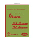
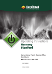
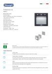
1
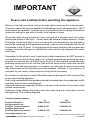
Operating Instructions
Harmony Oil
Stoves
Part No.
Serial Number
© EUROHEAT DISTRIBUTORS (H.B.S) LTD. Sept 2005
1
E & OE Instructions Part number IN1191 Ed A
H11##0205A
IMPORTANT
Please read carefully before operating this appliance
When you first light your stove it will go through what is known as the ‘curing process’.
The paint used on the stove is capable of withstanding a very high temperature, 650°C
and needs to be hardened. To do this your stove needs to be run at a high temperature
(maximum setting for gas and oil stoves) for a number of hours.
During this initial curing process the stove will give off a pungent smell and a blue
haze will be evident in the room. These fumes can activate a smoke detector, if fitted.
The length of time it will take to cure your stove will vary according to the total area of
paint to be cured and the temperature reached; under normal circumstances this will
be between 5 and 10 hours. During this period the room should not be occupied and
windows should be left open to ventilate the room and to help dissipate the smoke
and fumes.
Remember for the stove to cure it must reach a high temperature; do NOT attempt to
cure your stove on a low setting (gas or oil), at these temperatures the stove will never
properly cure and will give off a smell every time it is lit with multifuel stoves follow the
operating instructions for the first few fires and the stove will be cured after the first
high fire. Once the curing process is complete your stove can be used in the normal
way, the process will not normally need to be repeated. However, if you re-paint or fit
new parts to your stove, a short period of curing will be necessary.
Do not store or use petrol or other flammable vapours and liquids in the vicinity of this
or any other heating appliance.
Due to high temperatures the appliance should be located away from pedestrian traffic
and away from furniture and draperies.
Advise all adults and especially children to be alert to the hazard of the stove's high
surface temperatures.
Supervise young children the elderly and infirm when they are in the same room as
the appliance. Fit a suitable fireguard.
Contact telephone numbers:
Euroheat Reception
[email protected]
Euroheat Technical Support
[email protected]
Euroheat Spares Department
[email protected]
Tel
01885 491100
Fax
01885 491101
01885 491117
01885 491105
01885 491126
01885 491106
© EUROHEAT DISTRIBUTORS (H.B.S) LTD. Sept 2005
2
E & OE Instructions Part number IN1191 Ed A
H11##0205A
BEFORE LIGHTING THE STOVE
If being lit for the first time, or after a period of no use, remove the coal effect and ensure the burner is dry.
If the burner has been operating within the past two hours no attempt must be made to re-light the burner or
open the stove door until the stove and catalyser have cooled.
The “Arming Lever” should be set by lifting it upwards, once this has been armed it cannot be disarmed
manually and will only need to be reset if the over level trip has been activated.
If the flue draught is very low when lighting the burner it may be necessary to leave the stove door slightly
ajar until the flame becomes stable, but the stove must not be left unattended until the door is shut. If weather
conditions cause the burner to take too long in establishing sufficient draught the flame may become very
long and yellow as the oil level builds up in the burner. It is advisable to turn the oil control knob to “0” until the
flame is reduced to its normal size and colour before turning the control knob to “2” again. The stove should
not be turned to a setting higher then “2” until the flue has reached its operating temperature (½ to 1 hour
dependant upon flue construction).
Metering stem remote lever. Used
for cleaning
contaminates or air from the metering slot; turn oil control
to maximum position and tap lever sharply 5-10 times.
If the metering stem becomes stuck in the off position,
preventing oil from passing, after a period of non use, it
may be pulled up to free it.
Actuator Pin. Used to control the oil flow rate by means
of remotely operated devices such as a flexitemp.
Arming Lever
6
5
6
Ignition Button
0
2
2
3
3
4
4
5
0
It is normal for there to
be some backlash in
the movement of the
oil control knob.
1
Lighting Position
1
Off Position
ELECTRIC (PUSH BUTTON) IGNITION
To light the stove turn the oil control knob,on the top right hand side of the stove, to position “2”. The ignition
button on the right hand side of the stove pressed and held in until the oil ignites. The indicator light, on the
transformer, will illuminate to show that the ignition system is operating, and the oil will normally light within 1
to 1½ minutes, a popping sound may be heard as it ignites,when the ignition button should then be released.
The electric ignition system works by energizing a heating element positioned in the bottom of the burner. Oil
is drawn towards the element by the capillary action of a stainless steel wire gauze. The oil is heated until
it reaches its ignition temperature. If the burner fails to light after two minutes, do not continue attempting to
light the stove; turn off the oil supply and refer to the fault finding section of the stove installation manual.
© EUROHEAT DISTRIBUTORS (H.B.S) LTD. Sept 2005
3
E & OE Instructions Part number IN1191 Ed A
H11##0205A
LIGHTING THE STOVE MANUALLY
1. The oil supply to the stove should be turned on and the oil metering valve control knob should be turned
off which is indicated as position “0”.
2. Open the front door of the stove and lift out the fuel effect guard, fuel effect (very fragile) and catalyser,
taking care not to disturb the catalyser support ring. Examine the burner bottom for evidence of oil. If the
burner is dry, lighting may proceed. If oil is present no attempt should be made to light the stove until this oil
has been removed.
3. The oil control knob turned to position “1”. Oil will now enter the burner and should be allowed to wet the
burner bottom, a patch the size of a biscuit, (65mm diameter) before the control knob is returned to the “0”
position.
4. A piece of firelighter the size of a sugar cube or a waxed taper should be placed on the burner bottom,
centrally to the oil patch and lit with a long match or spill.
Removing Fuel Effect
Removing Fuel Effect Guard
1
2
1
2
3
4
3
4
5. The catalyser, fuel effect and fuel guard should be replaced, taking great care to install them correctly, the
stove door closed.
6. The oil metering valve should now be turned to position number “2” and the stove left at this setting until
the burner, stove and flue have warmed sufficiently to allow stable burning at higher settings,½ to1 hour
dependant upon flue construction.
Removing Catalyser With Tool Provided
Hook tool
Catalyser
Support Ring
Correct catalyser
positioning within
burner.
© EUROHEAT DISTRIBUTORS (H.B.S) LTD. Sept 2005
4
E & OE Instructions Part number IN1191 Ed A
H11##0205A
EXTINGUISHING THE BURNER
Turning the oil metering control knob to “0” will stop the supply of oil to the burner and cause it to extinguish.
When the oil control knob is turned back to “0” resistance will be felt and then with further pressure it will
“click” off. If the stove is to be left unlit for a period of time, the supply to the stove should be turned off at the
isolation tap.
MONTHLY MAINTENANCE
To ensure the burner is operating efficiently and capable of its maximum output the fuel inlet to the burner will
need to be kept free of carbon deposits by operating the de-coking lever weekly.
De-Coking using De-Coke assembly
This is accomplished by slackening the knurled brass nut a half-a-turn and withdrawing it no more than 35mm
(1½ inches). While rotating the lever insert it fully, then re-tighten the brass nut. if this operation is to be
undertaken with the stove lit, great care must be taken and the glove supplied with the stove MUST be used.
Accessing the De-Coking Assembly
De-Coking Assembly
Knurled Brass
Nut
Maximum 35mm
(1½ inches)
De-Coking using the Allen Key Tool
This operation must only be carried out with the stove TURNED OFF and COLD. The de-coking and inlet pipe
are located behind the lower door and to the right hand or left hand side of the burner pot. Remove the end
cap with the tool supplied with the stove. The tool is then inserted into the inlet pipe rotating it as it is pushed
in towards the burner, until the cardon deposits have been scraped clear of the inlet.
Unscrew the de-coke port end cap with
the tool supplied with the stove.
���������������
Insert the tool into the inlet pipe and rotate
the tool whilst pushing in towards the burner,
until the carbon has been scraped clear.
© EUROHEAT DISTRIBUTORS (H.B.S) LTD. Sept 2005
5
E & OE Instructions Part number IN1191 Ed A
H11##0205A
De-oking using the De-Coking Tool
This operation must only be carried out with the stove TURNED OFF and COLD. The decoking and inlet pipe
are located behind the lower door and to the right hand or left hand side of the burner pot. Unscrew the end
cap of the inlet pipe. The tool is then inserted into the inlet pipe and is pushed in towards the burner, until the
cardon deposits have been scraped clear of the inner surfaces of the inlet pipe.
Remove the cap from the inlet pipe.
Push the tool into the pipe
Scrape the cardon deposits from the inner surfaces
© EUROHEAT DISTRIBUTORS (H.B.S) LTD. Sept 2005
6
E & OE Instructions Part number IN1191 Ed A
H11##0205A
ANNUAL SERVICING
The stove should be serviced annually to ensure the burner is operating correctly, the flue is clear of soot and
the oil metering valve is operating correctly. It is important during the service that the oil control valve and in
line filter are examined for contamination by water or dirt and that all fuel pipes are sound with no evidence of
leaks. Ensure the oil metering stem lever has not become stuck, if it has pull upwards until it moves freely.
CLEANING YOUR OIL STOVE
Before attempting to clean your stove’s glass the stove must be extinguished and allowed to cool, as for
safety reasons it would be foolish to attempt cleaning when the stove is operating or still hot.
THE GLASS
The glass in your stove is specially formulated to withstand the very high temperatures generated within the
stove and proprietary glass cleaners are not recommended as their compositions may contain chemicals that
will weaken or etch into the glass.
First wipe the glass with a dry cotton cloth. Then if need be use newspaper moistened with water to which a little
vinegar has been added will normally remove most staining, but if cleaning becomes necessary too often we
advise you to review your operating procedures to determine whether cleaner and more efficient combustion can
be achieved. However well the stove burns it will become necessary to clean the glass occasionally particularly
after lighting or if the conditions are windy.
THE STOVE BODY
Dusting the stove may be carried out when the stove is at its minimum heat output temperature, using light
strokes of a real bristle paint brush. Thorough cleaning, or any attempt to remove marks on the stove body, must
only be done when the stove is cold. Stoves with an enamel finish should be cleaned with a damp cloth, or very
gentle use of a cleaner recommended for enamel finishes. It should be noted that even approved cleaners will
damage the highly polished finish of the stove if used too vigorously. All traces of the cleaner must be removed
before the stove is lit and no finishing polishes must ever be used, as these will leave unsightly streaks on the
stove when it becomes hot.
Stoves with a cast black finish must never be cleaned with a cloth as the texture of the paint will abrade and
collect lint from the cloth, which will be almost impossible to remove. Vigorous brushing with a stiff bristle
brush will remove all dust, but where the paint is marked, the stains are better obliterated with a spray of
suitable stove paint rather than attempts made to clean them off. Suitable paint may be purchased from a
stove shop or direct from Euroheat.
BRASS FITTINGS
Any proprietary brass cleaner may be used to clean the brass on the stove, but care must be taken to ensure
the polish does not come into contact with the stove enamel or the black cast finish, where it will leave a
stain.
THE BURNER
Together with routine operation of the decoking mechanism, the burner will need cleaning periodically to
ensure efficient burning. The frequency with which it will need cleaning is dependent upon the burner running
time and operating conditions, but the burner should be inspected monthly. The stove must be extinguished
and cold, with the ignition system, if fitted, electrically isolated before attempting to inspect or clean the
burner. If a coal effect is fitted to the stove, it should be withdrawn carefully, taking care not to touch the
“coals”, and put in a safe place; it is fragile. The catalyser should be lifted out, but no attempt must be made
to clean off the red-brown deposit. This deposit is the oxide of a chemical treatment applied to the catalyser
during manufacture and is essential to it performing correctly. The two-part inner ring should be removed for
cleaning, taking note of their positioning on the support pins. Only the burner bowl and fuel inlet pipe remain;
these can be cleaned of all carbon deposits using a suitable hardwood implement or, with great care, a blunt
screwdriver. (Excessive soft carbon or layers of very hard coke may be an indication of incorrectly adjusted
flue draught and your service engineer should be consulted.) When cleaned, the burner components must
be reassembled, taking care to fit the inner ring and catalyser correctly as soon as possible, to minimise the
risk of damage.
© EUROHEAT DISTRIBUTORS (H.B.S) LTD. Sept 2005
7
E & OE Instructions Part number IN1191 Ed A
H11##0205A
ECONOMIC OPERATION
The running cost of your stove is dependent upon many factors, and although it is possible to give the fuel
consumption figures of a stove at any set heat output, these will have little relevance to the actual running
cost of your stove because this will depend so much on the use made of the heat generated. The size
and insulation properties of your home will obviously be a major influence, but consideration given to the
way heat within the property is conserved and by the way in which the stove is operated may lower its fuel
consumption while maintaining acceptable comfort levels. When the stove is turned on to heat a cold house,
the time taken to give an acceptable temperature will depend not only on the volume of air but upon the
cooling effect of the walls and furnishings within the house. These will generate cold draughts of air, creating
a chill factor, and giving the impression of the ambient temperature being lower than it actually is. Leaving the
stove to run continuously at its minimum setting will alleviate this chill factor, and the actual temperature you
find comfortable will be lower. The extra fuel used during continual running will be offset against increased
comfort and lower acceptable ambient temperatures and may in some instances reduce the running costs of
the stove.
A sudden loss of burner capacity may be caused by low fuel levels, dirt (dog hairs) or an air bubble in the
fuel causing the oil metering valve to block. This can be cleared by turning the control knob to maximum and
pressing the metering stem lever on top of the oil valve, smartly, ten times.
Metering Stem remote lever.
Used for clearing contaminates
obstructing the metering
slot; turn oil control to six
then tap lever sharply
5-10 times.
Arming Lever (lift up to arm)
Once armed cannot
be de-armed
Actuator Pin
Used to control the flow
rate by remotely operated
devices such as the Flexitemp.
Euroheat, Efel and Nestor Martin have a policy of continual research and development and reserve
the right to modify its appliances without prior notice.
We make every effort to ensure that the information provided in this document is correct and accurate
at the time of printing. Continued updates occur to adapt documents to customer requirements and
appliance changes. For the latest editions of all Euroheat documentation visit our web site
www.euroheat.co.uk.
We would request that you inform Euroheat of information which you feel is not provided in this
document which would assist other users in the future.
The Euroheat Technical Team
© EUROHEAT DISTRIBUTORS (H.B.S) LTD. Sept 2005
8
E & OE Instructions Part number IN1191 Ed A
H11##0205A