1
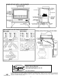
CAST-IRON GAS STOVE
INSTALLATION AND
OPERATING INSTRUCTIONS
For Tiger Stove with V125 Gas Burner
With Coals or Logs (Natural Gas or LPG)
LEAVE THIS DOCUMENT WITH THE HOUSEHOLDER !
TECHNICAL DATA
Natural Gas (G20)
IMPORTANT: It is most important that both the customer
and the installation engineer, not only follow the instructions Gas flow rate (m³/h) 0.52
in this booklet, but must be satisfied that all the following Input (kW)
5
conditions have been complied with.
Burner
This stove must not be used with any solid fuel; it is only
suitable for Natural Gas or liquefied petroleum gas (LPG) Injector
according to the burner unit supplied. Ensure that the local Injector pressure
gas distribution conditions, the gas pressure and the adjust- (high flame)
ment of the stove are compatible. Check that the burner
data plate (attached to the burner unit) corresponds with the
type of gas to be used ie. Natural Gas or LPG.
LPG (G31)
0.19
4.8
P4 48 Co Pilot
NG20/A/400/M9/BE
P4 49 Co Pilot
LP37/A/400/M9/BE
BRAY 82/460
BRAY 92/200
8.0 mbar
20 mbar
The site of the stove, the chimney, the flue and hearth etc., must comply with current Building regulations and Codes of
Practice before the stove is installed. The chimney flue outlet must be correctly positioned to align with the flue outlet on
the stove that you have bought. Connection to the chimney, the job of the installation engineer, is detailed in Section 1
LOCATION AND RECOMMENDED HEARTH SPECIFICATION: Your hearth should protrude at least 150mm (6") in front
of the stove body and be at least 12mm (1/2") thick. In most buildings with solid concrete floors this requirement will be
met by the floor itself. There should be a gap of at least 150mm (6") on either side of the stove, more if possible as the
greater the space the greater the amount of heat being released into the room. If the stove is to be fitted into an existing
opening there should be a minimum of 150mm (6") clearance on both sides, with the back of the flue diverter box 15mm
clear of the rear wall. On all stove installations no combustible material should cover the hearth, or be placed any closer
then 225mm (9") from the stove. This includes carpeting and other combustible floor coverings.
SAFETY REMINDERS: Tiger stoves are efficient appliances giving off convected, conducted and radiated heat. All the
surfaces of the stove - except the controls - are working surfaces and become hot in use. They must not be touched or
have any combustible objects or material placed on or near them. Adequate precautions should always be taken to protect
children, the elderly, the infirm and pets, etc. from coming into contact with the stove.
V125 Flue Spillage Monitoring System: Tiger stoves are fitted with an oxygen depletion sensitive pilot.
SECTION 1 - STOVE ASSEMBLY, INSTALLATION + COMMISSIONING
TO BE CARRIED OUT ONLY BY THE INSTALLATION ENGINEER.
MOST IMPORTANT: Before installing the stove, check that the burner data plate corresponds with the type of gas to be
used, ie. Natural Gas or LPG. Please make sure the customer is familiar with the initial lighting and operating procedures
before leaving the site and that this instruction booklet is left with them. Please check that the following components, delivered in 2 boxes, are included before you start on the assembly:
Box 1: Burner Unit and coal or log set.
Box 2: Stove Body inc. baffle and flue diverter and Allen Key for locking door handle.
STANDARD LEGS: Attach the legs if required. It is suggested that the two
legs with fixing holes be fitted to the back of the stove, for neater appearance. If the hearth is uneven, fit one or more extra washers between any leg
and the stove body to lengthen it.
COOKTOP KIT OPTION (supplied separately): Open the door and remove
the two bolts located to the left and right inside the underneath of the standard top. Remove and discard the standard top, taking care not to damage
the fibre seal. Fit the 'wings' to the cooktop and bolt the whole assembly
back onto the stove body. Do not over tighten.
HI-LEG KIT OPTION (supplied separately): Remove and discard the gas
control access hatch in the right-hand leg. Assemble the left, and right hilegs loosely to the central bridging member. Attach to the underside of the stove using the bolts supplied before fully tightening.
1
•
•
•
•
•
•
•
•
Loosen the locking screw for the door handle, located on side of door handle spindle, using the key supplied. Do not
attempt to open door without loosening the locking screw. The locking screw prevents unauthorised access.
Open door using handle and remove contents packed inside stove, including front fire bar.
Install the Internal Deflector inside the stove body as shown on the accompanying drawings, using the bolts provided.
Install the Diverter Box to the rear of the stove body as shown on the drawings, using the bolts provided
Fit the Flue Closing Plate between the Flue Collar and the top of the stove body, with the opening towards the back, as
shown.
Insert burner through door aperture with the control valve to the right-hand side, and the pilot light to the front..
Manoeuvre burner so that the rear lugs fit over rear base plate, and the front lugs sit on front of the base plate. Secure
with the 2 bolts supplied with the burner.
Fix the stove down to the hearth, through the legs, using the screws and plugs provided.
CONNECTION TO THE CHIMNEY: Before you install the stove make sure the chimney flue outlet is correctly positioned
to align with the flue outlet on the stove and that the chimney is in good condition. If not, a chimney liner must be installed
or a suitable class 2 gas flue used. A draught is necessary to ensure the products of combustion are fully evacuated. The
stove must be installed in accordance with current gas and building regulations applicable. Connect and seal the stove
flue collar to the chimney using full depth of collar. A minimum of 610 mm (2ft) of vertical pipe should be established before the flue direction is changed, unless the stove is to be used with a fanned (powered) flue. The flue must have a minimum height of 3 mtrs (10ft), however to ensure optimum performance we recommend 3.66 mtrs (12ft) or higher. The flue
must be free of obstruction and any dampers must be fixed in a permanently open position. Ensure the chimney is not
closed and that it has been swept prior to the stove being installed. Make sure that rain, birds or any foreign body cannot
get into the chimney to cause damage or a blockage. This problem can normally be overcome by fitting an approved Gas
Cowl. It is essential to the effective running of your stove that the chimney draws properly to allow the products of combustion to escape.
GAS CONNECTION: The gas connection must be property sized to provide the correct gas rate at the required running
pressure at the valve inlet, and the final connection to the stove is to be completed with a suitable 8mm diameter gas pipe.
It is essential that a gas isolation tap is provided upstream of the stove, in a position that is easily accessible.
GAS PRESSURE: Make sure that there is adequate gas pressure and volume to the stove. The relevant pressures are on
the data plate. Ensure that the gas pressure to the stove is maintained when it is operating at the same time as other appliances in the building. The burner gas pressure can be obtained by unscrewing the pressure test nipple on the valve and
applying a suitable pressure gauge i.e. a manometer. Before the coals or logs are placed in position make sure that the
burner is operating correctly. The flame should be fairly even across the burner top.
VENTILATION: Under normal circumstances no additional room ventilation is needed.
COALS OR LOGS LAYOUT: Refer to attached drawings
PRE-LIGHTING CHECKS
1. Ensure all the building work and flue sealing is complete.
2. Ensure the front fire bar is refitted in position.
3. Ensure all the coals or logs are correctly placed.
4. Close and secure the stove door.
5. Check that the stove door is completely sealed
6. Lock the stove door handle with the locking screw using key.
To the installation engineer: Please look at the section on stove lighting and commissioning and go through this with the
customer.
SECTION 2 - OPERATING INSTRUCTIONS FOR THE CUSTOMER
Please go through this section with the installation engineer so that you fully understand all the basic operating and maintenance procedures for your stove. The engineer will be happy to answer your questions and give you any help you may
need.
GENERAL NOTES: This stove is not for use with any solid fuels. It is only suitable for Natural (mains) Gas or LPG (liquid
petroleum gas) when the correct burner is fitted.
PLEASE REMEMBER THAT WHEN THE STOVE IS ALIGHT IT IS VERY HOT - EXCEPT FOR THE CONTROLS- NEVER TOUCH IT WITH YOUR BARE HANDS. The stove must not be touched when it is in operation. However, if you do
need to do so after it has been turned off and before it has completely cooled down (usually after about one hour) please
make sure that you wear stout oven gloves.
Flue Spillage Safety Monitoring Device- A Safety Cut-Off System: All stoves are fitted with an Oxygen Depletion Sensitive Pilot so that should the flue and/or chimney become blocked at any time the stove will automatically cut off. Normally
the pilot can be re-ignited after waiting about five minutes for the sensor to cool down. but in the event of the system tripping, have the flue and chimney checked by your installation engineer.
2
LIGHTING AND CONTROLLING THE STOVE: Remember that the stove is designed to be operated with the door securely closed.
1. Near the stove will be the gas isolation tap. Turn this to the on position.
2. Between the front and rear legs on the right hand side of the stove you will find the burner control knob.
When the stove is first operated it should be run at maximum for several hours to help the painted coating to cure. While
this happens slight fumes and smell may be apparent, which may linger for a week or so. This is normal and quite harmless. You may prefer to keep the room ventilated until the curing process is completed.
A. SWITCHING ON/ IGNITION. Depress the control knob & turn counter clockwise. Gas will flow to the pilot burner. The
piezo igniter will give off a high voltage spark & the pilot burner will light. (More than one attempt may have to be made on
first lighting the fire.) Keep the control knob depressed for approximately 10 seconds, then turn the control knob fully
counter clockwise to release gas to the main burner.
B. CONTROL OF GAS FLOW. Turning the control knob clockwise reduces the gas rate from the maximum to the pre-set
minimum setting. Turning between maximum & minimum does not actuate the piezo igniter. The control valve can only be
set on pilot by depressing the knob & turning it to the pre selected pilot position.
C. SWITCHING OFF WHEN IN PILOT POSITION. Press control knob and turn clockwise to off.
IMPORTANT - Interruption of Supplies. Should the stove burner cut out for any reason you should not try to relight it for at least 5 minutes. If you are then unable to re-light the pilot you should contact your stove supplier or
engineer. During normal operation, for example in the winter months when the stove will be in regular use, we advise that
the pilot is left running continuously as this will allow for quick and easy lighting, while at the same time helping to prevent
condensation. When the stove is not being used for long periods, i.e. in the summer then we advise that the gas supply is
turned off at the isolation tap.
CUSTOMER REMINDER: IT IS A LEGAL REQUIREMENT THAT THE COMPLETE ASSEMBLY, INSTALLATION AND
COMMISSIONING OF GAS FIRED STOVES IS CARRIED OUT BY A PROFESSIONALLY QUALIFIED AND ACCREDITED GAS FITTER. YOU MUST NOT ATTEMPT THIS YOURSELF.
SECTION 3 - MAINTENANCE & SERVICING PROCEDURES
FUME SPILLAGE CHECK: This test must be carried out by the installation engineer, when the stove is first commissioned, and we suggest thereafter every 12 months to ensure that the products of combustion are not spilling into the
room. The test is carried out by running the stove for ten minutes and then holding a smoke match close to the diverter
box to make sure the smoke is drawn up the into the flue way. Do not use a lighted match or a naked flame. The airflow
must be drawn to the chimney with sufficient draught. If the smoke is disturbed then repeat the test a few minutes later.
If the smoke is still disturbed by escaping products of combustion turn the stove off and contact your installation engineer.
SERVICING
For Safety And Efficient Operation servicing should be carried out annually by a qualified installation engineer.
When the stove is cold and the gas supply turned off at the isolation tap the following points should checked:
1. Remove all the coals or logs and clean any dust and debris from the top of the burner unit. Ideally a vacuum cleaner
should be used. but if not a soft brush will do.
2. Check the condition of the coals or logs. Any damaged ones will affect the efficient operation of the stove and should
be replaced with new ones available from your stove supplier.
3. All gas joints should be checked for soundness, and the gas supply and pressure checked as to specification.
4. Check that the pilot jet is correctly set and clear of obstruction.
5. The chimney should also be checked to make sure there are no restrictions or blockages.
6. Finally re-lay the coals or logs and light the stove as described earlier.
PROBLEM SOLVING: It is important that the installation engineer is contacted to rectify any difficulties.
The gas pilot will not stay alight:
1. Ensure there is a gas supply to the property and that the isolation tap is in the "on" position.
2. Hold the control knob in the lighting position for at least 20 seconds once the burner is alight, to ensure adequate
heat operation of the safety thermocouple valve.
3. Make sure that the pilot injector is not obstructed or blocked and that it is free from dust or dirt.
4. Finally ensure that the thermocouple, a very delicate electro-mechanical device, has not become damaged in
any way. If it is damaged a replacement pilot assembly should be obtained and fitted by your installation engineer.
FINAL REMINDERS: It is a legal requirement that the stove is installed by a qualified and accredited installation
engineer. Improper installation, adjustment, alteration, service or maintenance can cause injury and/or damage to
property. If you are in the slightest doubt about any aspect of your stove's performance or you require additional
information then please contact your stove supplier or qualified installation engineer. At the risk of stating the
obvious, please do not store, keep or use petrol or any other flammable liquids, vapours or substances anywhere
near the stove or any other heating appliance.
We hope these instructions have been clear and helpful and you are now able to enjoy the full benefit of your
stove. If you have any queries or have found the instructions not as straightforward as you would like, then
please don't hesitate to call us. Any suggestions for improvements are most welcome. Please keep these instructions safe for future reference.
3
Gallery Group Stoves
www.galleryfireplaces.co.uk
Tel: 0161 703 8157
Designed in England by Glyn Hughes Design. The Tiger Stove is registered design UK3019213, and is fully protected by Copyright ©
and UK Design Right, Glyn Hughes 1999/2005. Assembled in Gao Zhuangzi Village, Tianjin, China from components manufactured in
the USA, UK, Japan and China. The suppliers reserve the right to change any specification without notice. CD&P Act 'right of
recognition' is invoked. Issued g:15/06/05
4
5