1
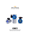
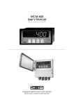
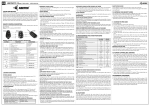
Operating Instructions Mains Water Top-UP Set: Compact Page 1 of 9 Contents Contents .............................................................................................................................. 1 Product Description ........................................................................................................ 2 Components ................................................................................................................ 2 Installation....................................................................................................................... 3 Control Unit ................................................................................................................ 3 Tundish ....................................................................................................................... 3 Level Probe ................................................................................................................. 4 Operation......................................................................................................................... 5 Control Unit Operation ............................................................................................... 5 LEDs ........................................................................................................................... 6 Internal Jumper Settings ............................................................................................. 6 Troubleshooting .............................................................................................................. 7 Specification ................................................................................................................... 9 Control Unit: ............................................................................................................... 9 Level probe: ................................................................................................................ 9 Solenoid valve:............................................................................................................ 9 Page 2 of 9 Product Description Automatic mains water top-up for rainwater tanks with leak detection feature and pump dry-run protection. Components 1 – Ball Valve 2 – 30cm Braided Steel Flexi Hose with Isolation Valve. To mains water feed. 3 – Solenoid Valve 4 – Tundish with Bracket. DN 40 Overflow. DN 50 Outlet. 5 – Control Unit 6 – Level Probe 7 – Schuko (European) Mains Plug. This is supplied in order to allow you to connect a pump to the European style mains socket on the front of the unit. Handling and Storage, Pre-installation. Do not leave outdoors in the rain. It is not waterproof. This is not an armoured or heavy-duty appliance, it will not survive impact and drops, crushing, etc. Do not leave on the floor. If damaged do not use it. Do not store with or upon cement, sand, plaster, etc. These materials will corrode the circuit board (and cause cosmetic damage). Do not install in a location subject to freezing temperatures. This may include outbuildings and uninsulated loft spaces. Page 3 of 9 Installation Control Unit We recommend installation to be carried out by a qualified electrician. The Control Unit must be mounted indoors in a dry place; it can be wall mounted using the supplied fittings. NOTE - It is not a waterproof unit. DO NOT install in a tank turret. We strongly recommends wiring the unit on an RCD protected circuit, in accordance with current best practice and regulatory requirements as defined by BS 7671, current IEE wiring regulations, and Part P of Building Regulations (where applicable). If in doubt consult a qualified electrician. We realize there are a wide variety of pumps supplied in the UK rainwater market, some with 2 pin schuko, and some with 3 pin UK plugs. A 2 pin schuko plug can plug directly into the plug socket on the face of the unit. If your pump has a 3 pin UK plug there are two options available. Change the pump’s plug to a 2 pin schuko plug (one is supplied with this kit) Use an earthed 2 pin schuko to 3 pin UK socket adapter to plug into the Control Unit’s pump socket (not supplied). SAFETY NOTE – European style Schuko plugs are not protected with a fuse, therefore it is vital the controller is installed on a 10A fused outlet to protect both the pump and controller. If in doubt you MUST consult a qualified electrician. Tundish The Tundish acts as an air gap to prevent backflow into the mains water supply, meeting the requirements of BS EN 13076. Please refer to the separate Tundish Installation Sheet for correct installation of the Tundish. If in doubt you should consult an approved and qualified plumber. Page 4 of 9 Level Probe The supplied conductivity Level Probe is used as a minimum water level detector in the rainwater tank. The standard length of cable supplied is 15m 1 To Control Unit (from level probe) 2 Water From Roof 3 Max Water Level (overflow) 4 Floating Intake from pump 5 Calmed Inlet 6 Sediment Layer 7 Level Probe 8 Approx. 0.3-0.4 m (guide only) 9 Minimum Water Level 10 Overflow 11 Sewer Connection Fix the Level Probe in the tank so that it is suspended approximately 0.3 to 0.4 metres above the bottom, depending on the shape of the tank and position of pump inlet. If in doubt you MUST consult an approved and qualified plumber. The height of the Level Probe determines the minimum water level of the tank at which the pump will run. The Level Probe works by conductivity; when the Level Probe’s contacts are immersed in water a circuit is completed and the control unit detects this. Note: The level probe’s cable can be extended to a maximum of 30m. OPERATIONAL ADVICE NOTE – Ensure that the tank is entirely free of debris before installing a pump and this controller. Plastic swarf from manufacturing and other debris will quickly clog any filters and may get caught in the pump’s impellers, prematurely shortening the operational life of the system, and invalidate pump and other component warranties. Maintenance Advice – It is good practice to clean the probe at intervals of three years, or when checking the tank. Page 5 of 9 Operation Control Unit Operation Test button: Pressing this when the Solenoid Valve is closed will momentarily open and close the Solenoid Valve. Stop/Reset button: Closes the solenoid valve and shuts off power to the pump. The Alarm LED will flash. A second press will reset the controller to its usual working state. When the Control Unit is powered up: High Water Level: If the Level Probe is below the water level in the tank then the green LED remains on, there is power to the pump socket (so a connected pump will run) and the solenoid valve is closed (not topping up). Low Water Level: If the water level falls below the level probe a top-up cycle will begin. The green LED flashes and the Solenoid Valve opens to allow mains water to flow through the Tundish into the rainwater tank. During the top-up cycle the pump will be turned off. Once the water level reaches the Level Probe again the pump is again allowed to run. The solenoid valve will remain open for a further minute before closing. The top-up cycle is now complete and the green LED changes from flashing to solid. Self Maintenance: The Control Unit will momentarily open and close the Solenoid Valve three times a week to prevent blockages. This process takes place automatically. Safety Shutdown: During a top-up cycle, if the water level in the tank has not reached the level probe after 30 minutes of topping up, the unit will shut off the pump and close the solenoid. The red alarm LED lights to indicate that there is a leak or blockage in the delivery to the tank, a failure of the tank itself, or a problem with the solenoid valve. Page 6 of 9 LEDs Green - Solid Normal Operation. Solenoid Valve closed. Pumps runs as usual. Water level sufficient. Green - Flashing Top-up cycle in progress. Solenoid Valve open (topping up). Pump switched off during top-up. Safety shutdown. Top up failed. Control Unit stopped manually (stop/reset button has been pressed). Red - Solid Red - Flashing Internal Jumper Settings This can be adjusted to increase the duration of the top-up cycle, and should be set by 3P in advance, or otherwise adjusted by a qualified electrician or electronic technician. The power supply MUST be disconnected before opening the Control Unit, there are hazardous voltages inside. For larger tanks and flow rates the jumper can be moved from the default position 1, to position 2. This position tops up much more water into the tank. In position 2 the pump shut-off delay and alarm delays are also increased accoridngly. If in doubt please consult a qualified electrician or electronic technician. Attention! The Control Unit must only be opened when it has been ensured that there is no power to the unit. Jumper Setting 1 2 Delay before pump shut-off during top-up 15 sec 10 min Top-up duration after level probe is reached 1 min 20 min Safety Shutdown delay 30 min 45 min Jumper setting 1: The pump will turn off 15 seconds after the beginning of a top-up cycle. The Solenoid Valve will close 1 minute after the water level reaches the Level Probe. If the water level doesn’t reach the Level Probe within 30 minutes the unit alarms. Jumper setting 2: The pump will turn off 10 minutes after the beginning of a top-up cycle. The Solenoid Valve will close 20 minutes after the water level reaches the Level Probe. If the water level doesn’t reach the Level Probe within 45 minutes the unit alarms. Page 7 of 9 Troubleshooting Symptom Solid Red LED – Controller has alarmed and shut down Possible Faults Solenoid is blocked Solution Press Reset, then test solenoid by pressing Test button. If solenoid clicks but no water flows, check the supply pipework and flexi-hose for blockages. If supply is clear but solenoid does not function, replace solenoid (call technical support) Solenoid has failed If solenoid does not click, check wiring from solenoid to controller for possible damage. If OK replace solenoid (call technical support) Solenoid functions normally, tundish overflows The supply pipe from tundish to tank is blocked. Clear blockage and retest. Solenoid functions normally, tundish does not overflow but tank does not fill No fault Check tundish to tank pipework by visually looking for top-up water entering the tank. If no water is present, suspect failure in pipework. If water is present suspect tank failure. Press the stop/reset button to reset the controller. Top-up cycle is too frequent causing pump to be shut off during demand for water Too small a top-up time is selected. Follow the Internal Jumper Settings instructions to change the jumper to position 2. Consult a qualified electrician before opening the Control Unit. Top-up cycle activates often, even when no water is drawn Possible tank failure or fault (leak) in supply pipes from pump. Shut down controller and pump and check tank water level periodically (during dry weather). If water level drops, suspect tank failure. Otherwise switch on controller and pump and check for leaks in outlet pipes from pump, and possible leaks of toilet float valves, etc. Controller does not function (no lights) Internal fuse failure Have the controller’s internal fuses checked by a qualified electrician and replaced if necessary. If the unit fails again, contact your supplier for replacement. Controller or associated Have the supply circuit checked by a qualified Flashing red LED – Controller has been stopped manually Page 8 of 9 Pump does not run, top-up and other functions seem ok For all other faults contact your supplier wiring has tripped the mains circuit breaker or RCD electrician. Check circuit breaker is of a suitable rating (16A Type B recommended), also test wiring insulation and earth. If the supply circuit is proved to have no fault, contact your supplier for replacement. Pump failure Unplug the pump and test separately. Controller Damaged The control unit can supply up to 10A at 240v to the pump. It may be damaged if this specification is exceeded. Page 9 of 9 Specification Control Unit: Dimensions (W x H x D): 97 x 163 x 62 mm Weight: 0.5 kg Supply voltage: AC 230-240 V 50 Hz Power consumption: max. 5 VA Internal fuse: 32 mA Pump power outlet socket: AC 230-240 V, max. 10 A Mains Plug Fuse: T 10 A Operating temperature range: Ambient: 0 °C to +40 °C Protection class: II (DIN 57 700) Protection: IP 20 (EN 60529) Noise suppression: According to EN 50081-1 Noise immunity: According to EN 50082-1 Level probe: Supply voltage: AC 6 V Probe current: 1.2 mA Cable length: 15m (max. 30m) Dimensions of probe (L x Ø): 87 x 30 mm Weight: 0.2 kg Principle of operation: Conductivity Medium: Clean water Solenoid valve: Dimensions (W x H x D): 95 x 80 x 100 mm Weight: 0.5 kg Supply voltage: AC 230-240 V 50 Hz Power consumption: max. 5.5 VA Connection cable: 3 m Mounting position: Any Medium: Clean water Nominal pressure: 12 bar Flow rate at 4 bar inlet pressure and open outlet: approx. 50 l/min Function: Closed when de-energised Connection: Inlet: ¾” BSP union nut with in-line filter Outlet: ½” BSP female thread Protection: IP 65 (EN 60529)