1
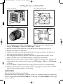
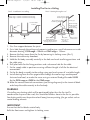
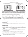
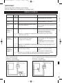
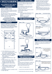
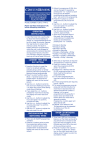
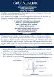
G510 Ins:Layout 1
1/11/12
10:51
Page 1
Installation & Operating Instructions
For Extractor Fans 4” Models: G510, G510PC, G510T, G510HS
For Extractor Fans 6” Models: G242, G242PC, G242T, G242HS
Thank you for purchasing a quality Extractor Fan from GreenBrook. Please read these
instructions fully prior to initial use.
Every effort has been made to ensure that the guidance information on this sheet will
enable the installation of the fan to be carried out safely and correctly.
IMPORTANT
This product should be installed by a competent person and
in accordance with the current IEE Wiring Regulations.
If in doubt, consult a qualified electrician.
When installing fans, switch off mains supply before making any electrical
connections.
1. All fans may be fitted to a wall or window.
2. These fans are double insulated and do not require an earth connection.
3. Fan models without an integral pullcord switch option can be fitted in a ceiling
providing adequate condensation control and suitable ducting runs are used.
4. The fans electrical supply must be connected via a double pole switched fuse
connection unit, having a contact separation of at least 3mm in all poles fitted with a
3 amp fuse. This must be sited outside of a room containing a fixed bath or shower.
5. For best performance, fans should be mounted on a wall as high as possible.
6. Wall mounted fans are not intended for use with ducting beyond 2 metres in length.
7. Extraction fans should not be located in rooms containing open flued appliances, or
where the normal air temperature may exceed 40°C or in an area containing excessive
levels of grease.
8. They must NOT be fitted in a shower cubicle or above a bath, or where there is any
possibility of liquid spray.
INSTALLATION
Select a suitable mounting position for the fan ensuring there are no hidden
obstructions and work out the cable runs.
Please Note: Using long lengths of ducting will reduce the efficiency of the fan,
whenever possible keep the ducting straight and the distances as short a possible.
Warning: Ensure that the mains supply is isolated before making any electrical
connections.
4
G510 Ins:Layout 1
1/11/12
10:51
Page 2
Installing The Fan in an External Wall
Dia 1- Front Cover
Dia 2- Internal Fan Layout
Terminal Block
(To the top)
Cable
Clamp
Fixing
Holes
Cable Entry
Knockout
Fixing
Holes
Fixing
Screw
Dia 3 - Wall Kit
Front Cover Locking Screw
Dia 4 - Installation in an External Wall
Cavity
External
Wall
External
Grille
Fixed
Grill or
Cavity
Shutter
Possible
Cable
Position
Fan
Flexible
Ducting
(G510 100mm)
(G242 155mm)
Inside Diameter Ducting
Interior
Wall
1. Cut a hole through the wall, sized to give a small clearance on inside diameter
ducting: G510 range = 100mm or G242 range = 155mm.
2. Remove the front cover from the fan by loosening its locking screw (Dia.1)
3. Remove the cable entry knockout.
4. Hold the fan body assembly (terminal block to the top) centrally in the hole and
mark two fixing positions and the cable entry.
5. Drill and plug the two fixing positions and chase a groove for the cable. Fix the
cable in position,ensuring sufficient length is left for the connections.
6. Bridge the wall cavity using a length of rigid or flexible inside diameter ducting and
make good the wall surfaces where necessary. G510 range = 100mm or G242 range
= 155mm.
7. Fix the fan body assembly to the wall using pan head screws of a suitable length.
8. Make the correct electrical connections (see wiring diagrams) to the terminal block
and clamp the cable securely to the fan body.
4
W
c
IMPORTANT
Ensure that the fan blades rotate freely.
Refit the front cover and tighten its locking screw. Fit a suitable external grille or gravity
shutter KingShield models G425/G400 for G510 range, and G625/G600 for G242 range
shown in Dia 3.
G510 Ins:Layout 1
1/11/12
10:51
Page 3
Installing The Fan in a Ceiling
Dia 5 - Installation in a ceiling
Dia 6 - Venting through a roof
G510 range = 100mm Inside Diameter Ducting
G242 range = 155mm Inside Diameter Ducting
Roof cowl and
weathering slate
Roof cowl and
weathering slate
Plastic pipe
Possible Cable
Position
(G510 100mm)
(G242 155mm)
Inside dia
flexible ducting
Joist
Fixed Grille
Support
Fan
(G510 100mm)
(G242 155mm)
Inside dia flexible ducting
sloping away from fan
Fan
Fan
Fan
Trap for major
Trap with
water run off condensation
for major
condensation
1. Fit a firm support between the joists.
2. Cut a hole through the ceiling and support sized to give a small clearance on inside
diameter ducting. G510 range = 100mm or G242 range = 155mm
3. Remove the front cover from the fan by loosening its locking screw (Dia.1)
4. Remove the cable entry knockout.
5. Hold the fan body assembly centrally in the hole and mark two fixing positions and
the cable entry.
6. Drill pilot holes for the fixing positions and a clearance hole for the cable.
7. Fix the supply cable in position ensuring sufficient length is left for the electrical
connections.
8. Fix the fan body assembly to the ceiling using pan head screws of a suitable length.
9. Install ducting from the fan spigot either through the roof using a weatherproof
slate and roof cowl, or under the eaves using an external fixed grille model G425
for the G510 range or G625 for the G242 range.
10.Make the correct electrical connections (see wiring diagrams) to the terminal block
and clamp the cable securely to the fan body.
WARNING
If installing any ducting which will be positioned higher than the fan itself, a
condensation trap must be used, this should be fitted as close to the fan as possible.
Fan ducting outlet must be positioned well away from any existing flue gas outlets such as
central heating exhausts
IMPORTANT
Ensure that the fan blades rotate freely.
Refit the front cover and tighten its locking screw.
G510 Ins:Layout 1
1/11/12
10:51
Page 4
Installing the Fan in a Window
Dia 7- Window Conversion Kit
Dia 8 - Installation in a Window
Glass
External
Casing
Internal
Casing
30mm
Clamping
Screws
Fixed
Grill or
Cavity
Shutter
Gasket
Fan Body
Assembly
10mm
Fixing
Screws
Fan
Front Cover
Please Note: This installation requires a window fan and a conversion kit KingShield
models CK4GS or CK4FG for G510 range or CK6GS or CK6FG for G242 range. Fans can
be fitted into most types of glass with varying thickness (including double glazed units)
from 4mm to 28mm. It is advisable to have the hole pre-cut in a new pane of glass by a
professional glazier. If the fan is to be mounted in hermetically sealed double glazing it
will be necessary to obtain a window from a glazing manufacturer.
1. Pre-cut diameter hole in the glass: G510 range =140mm or G242 range =184mm.
2. Remove the front cover from the fan by loosening its locking screw (Dia.1)
3. Undo the clamping screws G510 range = 2 x 30mm or G242 range 4 x 30mm,
positioned top and bottom on the internal casing and separate from the external
casing.
IMPORTANT
Ensure the sealing gaskets are fitted correctly to the edges of the casings.
From the Inside:
1. With the clamping screw holes positioned top and bottom, place the internal casing
and gasket centrally in the hole.
From the Outside:
1. With the louvres/shutters slanting downward, re-locate the external casing and
gasket squarely on to the internal casing.
2. Re-locate and tighten the two (or four) clamping screws sufficiently to create a seal on
the glass.
DO NOT OVERTIGHTEN
3. Fix the fan body assembly to the internal casing (terminal block to the top) using the
two 10mm fixing screws.
4. Fix the cable in position, ensuring sufficient length is left for the connections.
5. Remove the knockout or form a suitable cable entry in the front cover (not
immediately above the overrun timer when fitted).
6. Make the correct electrical connections (see wiring diagrams) to the terminal block
and clamp the cable securely to the fan body.
G510 Ins:Layout 1
1/11/12
10:51
Page 5
IMPORTANT
f
Ensure that the fan blades rotates freely.
Refit the front cover and tighten its locking screw.
WIRING DIAGRAMS
Model
Standard
Wiring
Description
Diagram
For remote switching
9
Operating
Remote switch on - Fan runs
Remote switch off - Fan stops
T
f
O
T
o
Pullcord
Switch
11
Integral pullcord switch
Pullcord switch on - Fan runs
Pullcord Switch off - Fan stops
Overrun
Timer
12
Adjustable (2-30 min) Overrun timer
for remote switching.
Remote switch on - Fan runs
Remote Switch off - Fan overruns for
preset time
e
t
Overrun
Timer
& Pullcord
Switch
12
Integral pullcord switch
As above
- Pull momentary pullcord for about
1 second to activate timer
- Fan overruns for preset time.
Requires no switched live supply when operated by integral momentary
- pullcord switch only
c
2
11
Overrun
Timer &
Humidistat
12
11
Overrun
Timer &
Humidistat
& Pullcord
Switch
12
11
Remote switch on - Fan runs
Remote switch off - Fan overruns for
preset time.
Automatic operation when relative
humidity level in room rises above
70%
Requires no switched live supply when operated by integral humidity sensor
switching only
As above with integral momentary
As above - Pull momentary pullcord
for about 1 second to activate
pullcord switch override.
timer
- Fan overruns for preset time.
Adjustable (2-30 min) Overrun timer
for remote switching. Integral
humidity sensor switching.
Requires no switched live supply when operated by integral humidity
sensor switching and integral momentary pullcord switch only
Dia 10 - Integral Pullcord Switch Operated Models
Terminal L - Live Supply
Terminal N - Neutral Supply
Dia 9 - Standard Models
Terminal L - Live Supply
Terminal N - Neutral Supply
Extractor Fan
Double Pole Switched
Fused Connection Unit
3Amp Fuse Fitted
Pullcord
Switch
Extractor Fan
Double Pole Switched
Fused Connection Unit
3Amp Fuse Fitted
C
f
G510 Ins:Layout 1
1/11/12
10:51
Page 6
Dia 11 - Overrun Timer and Humidistat Models
for Remote Pullcord Switch Operation
Terminal L Terminal T Terminal N -
Extractor Fan
Double Pole Switched
Fused Connection Unit
3Amp Fuse Fitted
Permanent Live Supply
Switched Live Supply
Neutral Supply
Ceiling
Junction Box
PLEASE NOTE
The fan motor has an automatic cut out switch
for protection against overload or misuse.
Pullcord
Switch
+
L
OVERRUN TIMER MODELS
To comply with current building regulations the
overrun timer has been preset for approximately Dia 12- Timer Control
15 minutes. To reduce the overrun time, first
ensure the fan is isolated from the mains supply,
then remove the front cover by loosening its
locking screw and turn the timer control
_
clockwise on the timer board. Adjustable from
T
2 - 30 minutes.
N
HUMIDISTAT MODELS
Upon initial installation, the fan may run continuously for up to 10 days until the relative humidity
has been reduced to an acceptable level. Prevailing weather conditions can also have its effect
and in humid conditions its normal running periods may be extended.
CLEANING
Before cleaning, ensure the fan is isolated from the mains supply. The front cover of the fan may
be cleaned with a damp cloth. The interior of the fan should be cleaned occasionally. To do this,
first remove the front cover by loosening its locking screw, then clean carefully with a dry cloth
if necessary the fan blade may be cleaned with a soft brush.
NOTE: A direct replacement, without a wiring change, need not be notified to your Building
Control Department.
TECHNICAL INFORMATION
Rated voltage:
Load:
IP Rating:
Insulated:
Air Movement:
4” (G510)
6” (G242)
230V AC - 50Hz
G510 - 17W Maximum, G242 - 25W Maximum
IP22
Class II Double
Up to 80 Cubic Metres/Hour (22.2 Litres/Sec)
Up to 230 Cubic Metres/Hour (64 Litres/Sec)
GUARANTEE
Your KingShield 4”/6” Extractor Fan is guaranteed for 12 months from the date of purchase.
This is in addition to your statutory rights.
PLEASE KEEP THESE INSTRUCTIONS
SAFE FOR FUTURE REFERENCE
[email protected]
W W W. G R E E N B R O O K . C O . U K
Issue no: 703032
WEST ROAD . HARLOW
ESSEX . CM20 2BG . UK