1
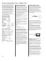
Bruksanvisning & installationsanvisning – Compact 3020
Operating instructions & installation instructions – Compact 3020
Bedienungsanleitung & Installationsanleitung – Compact 3020
Gebruiksaanwijzing & installatievoorschriften – Compact 3020
Käyttöohje & asennusohje – Compact 3020
Bruksanvisning og installasjonsanvisning – Compact 3020
Notice d´emploi & manuel d´installation – Compact 3020
Istruzioni per l’uso e Istruzioni per l’installazione – Compact 3020
Navodilo za uporabu & navodilo za instalacijo – Compact 3020
,QVWUXNFMD2EVãXJLZUD]],QVWUXNFMD,QVWDODFML²&RPSDFW
Instrucciones de manejo e instalación – Compact 3020
A
B
1
min 5
20
16
15
TOP OBEN
14
12
rek. min 320
13
7
8
40
min 4
535
min
2
C
10b
9
D
10a
11
E
40
41a
39
4
min 220 mm
17
6
5
MENU
34
38
19
41b
20
16
Ø 76 mm
42
35
13
12
36
15
37 43
18
14
-
+
12V DC
44
F
28
26
27
23
24
21
25
29
22
71
Please read these instructions carefully before using the boiler for the !rst
time. The operating and installation
instructions for the control panel are
provided separately.
These instructions are approved for the
Alde Compact 3020 boiler !tted in caravans, motor caravans or buildings in
accordance with CE 0402 no. SC0653-13
and have the E5 mark for installation in
vehicles in accordance with ECE R122,
no. 00 001 and R10, no. 04 166.
Installation and repairs may only be carried out by a specialist. Always comply
with national regulations.
BOILER DESIGN
The boiler consists of three eccentrically
mounted pipes (the heat exchanger, the
water jacket for the heating system and,
on the outside, the water jacket for the
hot water). The two outer pipes, and their
ends and connections, are made of stainless steel, while the heat exchanger is
made of aluminium.
The heat exchanger is split into two
hemispheres. The burner is located in
the top half which forms the combustion
chamber, and the "ue gases are expelled
through the bottom half.
The burner unit is mounted on the end of
the heat exchanger. It consists of a combustion fan, burner, solenoid valve and
intake/exhaust gas connections.
Two electric elements are !tted in the
water jacket for the heating system
Their maximum output is 2 or 3 kW
depending on the model.
DESCRIPTION OF FUNCTIONS
Operation using LPG
When LPG operation is selected on the
control panel, the combustion fan starts
up. Once the correct speed is attained, a
signal is sent to the circuit board that the
boiler can be lit. Ignition sparks are sent
from the spark plug at the same time as
the solenoid valve opens to allow gas in.
The burner ignites, and a sensor transmits a signal back to the circuit board
that the boiler is lit, and the ignition spark
stops. The burner keeps burning until the
boiler thermostat or the room thermostat
reaches the set temperature value.
Should the boiler go out for any reason,
the sensor will detect this and a new
attempt is made to start the boiler (for
about 10 seconds).
Operation using the electric heating element(s)
When electrical operation is selected in
one of the power modes on the control
panel, the 12-volt relays on the circuit
board trip, allowing the 230-240 volt
supply to reach the electric elements. The
electric elements are controlled in the
same way as the LPG boiler.
Domestic hot water
When hot water only is required, during
the summer for instance, no settings need
be made; the boiler looks after this function automatically.
The pump will only start once the temperature in the vehicle is lower than the set
temperature (see point 4, control panel).
If the temperature in the vehicle is higher,
the pump will not start.
IMPORTANT INFORMATION
1. Switch off the freshwater pump.
2. Open all water taps.
3. Then open the safety/drain valve by
raising the yellow lever (M) to a vertical
position, or by turning the knob (K) 180°.
4. The heater will now drain directly below
the vehicle through the safety/drain
valve hose. Check that all the water is
emptied out (about 7-10 litres). Leave
the valve in the open position until the
next time the heater is used.
NB" Check that the automatic non-return
valve (N) is open and is allowing air to
enter the heater when it is being drained,
and that the hose is not blocked.
• The boiler must not be started if
there is no ethylene glycol "uid in the
system.
• Ethylene glycol "uid may be heated
even if the hot water heater is not !lled
with freshwater.
• The LPG boiler and electric elements
may be operated simultaneously.
• Always switch off the main isolating
switch for the boiler when the vehicle is
not in use.
• Always drain the hot water heater of
freshwater if there is a risk of frost.
• The LPG boiler must not be in operation when refuelling the vehicle at a
garage or similar.
• When washing the vehicle, take care
not to wash right up against the roof
vent.
Opening the manual
safety/drain valve
THE DOMESTIC HOT
WATER HEATER
Opening the automatic
safety/drain valve
The boiler is !tted with a built-in hot water
heater which can hold approximately 8.5
litres of freshwater. The hot water heater
can produce around 12 litres of 40°C
water per half-hour (at a cold water temperature of 10°C). If the electric elements
are used instead of gas for heating the
water heater, the capacity is slightly reduced.
Always "ush out the heater before it is
used, particularly if it has not been in
operation for some time.
NB" The hot water is not intended as
drinking water or for cooking purposes.
When the heater is in continuous use, it
should be emptied approximately once a
month, to create a new air cushion inside
it. The air cushion is used to absorb pressure surges in the heater.
For emptying specially-adapted
boilers, as well as the vehicle’s general
freshwater system, please refer to the
manufacturer’s instructions.
NB" The hot water heater should
always be drained down completely
when there is a risk of frost and the
vehicle is not in use. The warranty
does not cover frost damage.
Cosed
M
Open
K
N
9
GB
OPERATING INSTRUCTIONS – COMPACT 3020
THE ELECTRIC ELEMENTS
All Compact 3020s are !tted with two
230–240 V electric elements with a
maximum output of 2100 or 3150 watts,
depending on model. The output of the
electric elements is selected on the control panel.
Always check that the input fuse of the
vehicle has the correct amperage in relation to the selected output.
An output of 1050 W requires a 6 amp
fuse.
An output of 2100 W requires a 10 amp
fuse.
An output of 3150 W requires a 16 amp
fuse.
THE CIRCULATION PUMP
A circulation pump is required to circulate
the heated ethylene glycol "uid through
the heating system. There are three types
of circulation pump:
• 12 V circulation pump for !tting in the
expansion tank
• 12 V circulation pump for !tting to the
boiler
• 230–240 V circulation pump for !tting
to the boiler.
If more than one circulation pump is installed, the required circulation pump can be
selected via the control panel. The control
panel’s room thermostat is used to control
the circulation pump, i.e. switching it on or
off, as determined by the heating requirement.
MAINTAINING THE HEATING
SYSTEM
Camping in winter
If camping during the winter, ensure that
the "ue is kept clear of snow and ice, as
the intake air to the LPG boiler enters
through the "ue
Do not start the LPG boiler until the roof
vent is completely free of snow. If a roof
"ue is !tted, a "ue extension (part no.
3000 320) is available for camping in
winter.
The LPG system
The LPG system should be checked regularly by a specialist, who will ensure that
there are no leaks from connections or
hoses.
LPG hoses should be changed as indicated on the date stamp, as they tend to dry
out and crack, and are liable to leak as a
result.
For increased safety, we recommend
!tting an Alde leak detector, type 4071, as
close as possible to the reducing regulator.
AIR CIRCULATION
In order to exploit the water-borne heat
design to the full, it is important that air
can circulate freely under bunks, and
behind backrests and wall-mounted cabinets. If the vehicle has a !tted carpet, for
instance, ensure that the carpet does not
obstruct the air supply to the convectors.
It is just as important that cushions or
blankets do not obstruct the "ow of air
behind backrests and wall cabinets.
Air "ow
Convectors
10
FILLING THE SYSTEM WITH
ETHYLENE GLYCOL FLUID
NB" Any vessels used for handling or
mixing the liquid must be spotlessly clean,
and the pipes in the heating system must
be free of contamination. This is to prevent the growth of bacteria in the system.
The system is !lled through the expansion
tank, either manually or using the Alde !lling pump, which both tops up and bleeds
the system. For manual !lling, unfasten
the circulation pump nut (R) and then lift
the pump (S) out of the tank. Slowly pour
the ethylene glycol mixture into the tank.
Bleed the system. Top up with more "uid
if the level has fallen after bleeding. Bleed
a newly !lled heating system regularly
during the !rst days it is in operation.
Leak detector, type 4071
S
SYSTEM TEMPERATURE
The boiler is set to a system temperature
of 80°C, i.e. the temperature of the ethylene glycol "uid as it circulates through the
heating system.
quality of ethylene glycol mixture as is
already in the system, alternatively use
Alde Premium Antifreeze, which is compatible with most ethylene glycol brands on
the market.
Never allow the heating system to stand
empty of ethylene glycol "uid.
R
The heating system
Regularly check the heating system’s
"uid level in the expansion tank. The level
should be about 1 cm above the minimum
mark, with the boiler cold.
The heating system should be !lled with
a "uid mixture made up from water and
ethylene glycol. For best results, use highquality ready-mixed ethylene glycol (with
inhibitors) intended for use in aluminium
heating systems. The proportions when
using concentrated ethylene glycol are
60% water and 40% ethylene glycol. If the
heating system is likely to be exposed to
temperatures below -25°C, the ethylene
glycol content must be increased, but
should not exceed 50%.
Any vessels used for handling or mixing
the liquid must be spotlessly clean, and
the pipes in the heating system must be
free of contamination. This is to prevent
the growth of bacteria in the system.
The ethylene glycol mixture should be
changed every other year, as certain properties such as corrosion protection deteriorate over time. If Alde Premium Antifreeze is used, the interval for changing
the mixture can be extended to !ve years
under normal operating conditions.
If the "uid level is too low, the ethylene
glycol content must be checked before
topping up. This is to prevent excessive
concentration of ethylene glycol in the
mixture. When topping up, use the same
ABOUT LPG
TROUBLESHOOTING
Depending on how the pipes have been
!tted, air pockets may form when the
system is !lled with ethylene glycol "uid.
If the pipes only warm up a metre or so
from the boiler, even though the circulation pump is operating, this is a symptom
of air trapped in the system.
In a newly !lled system, small air bubbles
can form in the expansion tank, resulting
in a gurgling sound. Switch off the circulation pump for a few seconds to allow the
bubbles to disappear.
Bleed as follows:
If a bleed screw is !tted to the outgoing
pipe of the boiler, open this screw and
leave it open until "uid starts coming out.
If the boiler is !tted with an automatic
bleeder, the boiler will be bled automatically. Start the LPG boiler. The circulation
pump should be switched off. Open the
remaining bleed screws in the system
(please refer to the instruction manual of
the vehicle for their locations).
Leave the bleed screws open until ethylene glycol "uid starts coming out of them,
and then close them. Start the circulation
pump and let it run for a while. See if the
pipes and radiators are heating up around
the vehicle.
If this does not help, you can try the
following method:
Single-axle caravan: Switch off the
circulation pump. Tilt the caravan forwards. Leave it in this position for a few
minutes to allow the air to travel upwards
in the system. Open the bleed screw located at the highest point. Leave it open until
ethylene glycol "uid comes out. Proceed
in the same manner but with the caravan
tilted backwards. Then position the caravan horizontally and start the circulation
pump. See if the pipes and radiators are
heating up around the vehicle.
Motor caravan or twin-axle caravan:
For these, the easiest way to bleed the
system is to park the vehicle on sloping
ground or to raise one end of the vehicle
using a jack. Bleed the system as described above.
The properties of LPG
If the boiler is !tted with a digital control
panel, always start by checking any error
messages.
LPG is a petroleum product. Its full
name is “liquid petroleum gas”. Its main
constituents are the gases propane and
butane. The advantage of propane is that
it remains gaseous at temperatures as low
as -40°C, whereas butane is less effective
below +10°C. For this reason, propane is
used in colder countries.
The cylinders contain LPG in liquid and
gaseous form. When the cylinders are
!lled, the pressure turns the gas into liquid
form. When the cylinder valve is later
opened, the LPG reverts to its gaseous
form.
The risk with LPG is that any leaking gas
may ignite and explode. Since LPG is
heavier than air, any leaking gas will tend
to collect at the lowest point.
LPG contains no toxic substances. However, inhalation of concentrated gas may
have a certain anaesthetising effect, and
can also result in shortness of breath and
symptoms of suffocation. These symptoms quickly disappear once ordinary air
or oxygen is inhaled.
Naturally, it is not advisable to expose
yourself to situations where you risk inhaling either LPG or exhaust gases.
To make it easier to detect a potential leak
of LPG, a substance with a distinctive
pungent odour has been added to it.
Combustion
When LPG is fully combusted, only
carbon dioxide (CO2) and water vapour
are given off, just like in the air we exhale.
A good supply of air is essential to ensure
full combustion.
WARNING: Always make sure the "ue
outlet is well ventilated. It is not a good
idea to inhale the exhaust gases. Make
sure the "ue does not exit into an enclosed area, e.g. an awning.
LPG is very easy on the environment and
does not generate soot once fully combusted.
It can be stored in cylinders for an unlimited period without any deterioration in
quality.
The boiler will not start on gas
1. No LPG?
2. Is the main tap fully open?
3. Check that the type of LPG used is
suitable for the prevailing outdoor temperature. Butane is unsuitable for use
at temperatures lower than +10°C. Use
propane instead.
4. If the boiler has not been operated for
some time, or if the LPG cylinder is
new, it may take longer than normal to
light the boiler.
5. Check that power is being supplied to
the boiler (> 11 V).
6. Check that the fuse for the boiler has
not blown.
7. Check whether the electrical connections on the boiler are secure and tight.
8. If none of the above helps, contact a
9. service workshop.
The electric element is not working
1. Check that power (230–240 V) is being
supplied to the electric element.
2. Check that the relays !tted to the
boiler come on (a slight click can be
heard from the relays when the electric
element is switched on at the control
panel).
3. If none of the above helps, contact a
service workshop.
WARRANTY
Alde’s warranty is valid for one year from
date of delivery and is restricted to defects
of material or manufacture. It is conditional on the boiler having been installed and
operated in accordance with the installation and operating instructions.
The warranty does not cover frost
damage.
NB" Only original parts from Alde are to
be used as spare parts.
Pressure
The LPG burner works at a lower pressure than that in the cylinder. Low pressure (0-50 mbar) and medium pressure
(50 mbar-2.0 bar) are obtained by sending
the LPG through a reducing regulator.
High pressure (above 2.0 bar) is unreduced pressure used mainly in camping
equipment. Low pressure and medium
pressure always result from a reduction in
pressure.
11
GB
BLEEDING THE SYSTEM
INSTALLATION INSTRUCTIONS – COMPACT 3020
These instructions deal with the installation and assembly of the boiler and
expansion tank. Read these instructions carefully before !tting the boiler.
These instructions are approved for the
Alde Compact 3020 boiler •tted in caravans, motor caravans or buildings in
accordance with CE 0402 no. SC0653-13
and have the E5 mark for installation in
vehicles in accordance with ECE R122,
no. 00 001 and R10, no. 04 166.
Installation and repairs may only be carried out by a specialist. Always comply
with national regulations.
TECHNICAL DATA
Measurements/Weight
Boiler height:
310 mm
Boiler width:
340 mm
Boiler length:
510 mm
Weight: 14 kg (without "uid)
Gas:
Propane
Butane
Output Stage 1: 3.3 kW
3.8 kW
Consumption:
245 g/h
275 g/h
Output Stage 2: 5.5 kW
6.4 kW
Consumption:
405 g/h
460 g/h
Pressure:
I3+ 28-30/37 mbar
I3B/P 30 mbar
Volume/Pressure/Temp.
Volume of liquid, radiator water: 3.5
litres
Volume of liquid, domestic hot water:
8.4 litres
Maximum pressure, radiator water:
0.05 MPa
(0.5 bar)
Maximum pressure, domestic hot
water: 0.3 MPa
(3.0 bar)
System temperature: 85°C max.
230–240 V
Output, element: 1 x 1050 W
(2 or 3 kW)
1 x 2100 W
12 V DC
Power consumption: 1 amp (max.)
Fuse:
3.15 amp+/3.15 amp-
12
BOILER INSTALLATION
FITTING A WALL FLUE
The best place for the boiler is in a
wardrobe or storage space, but it can also
be located under the "oor of the vehicle.
If located outside the vehicle, the boiler
should be built into an enclosed space
so that it is protected from water spray,
exhaust fumes, etc. In choosing the location, also bear in mind the need to be able
to remove the service panel (A 1) and that
room should be left for replacement of
components during servicing.
The rating plate on the boiler must be
legible after installation.
The !tting dimensions given in Fig. A are
recommended
minimum dimensions when !tting the
boiler.
The space where the boiler is to be !tted
must be ventilated, with a ventilation area
of at least 70 cm2.
The boiler must be screwed securely to
the "oor through the holes in the !xing
brackets (A 2).
NB" The boiler must not be located in the
passenger area of a vehicle of type M2
or M3.
Fig. A
1. Service panel
2. Holes for !xing with screws
The boiler may only be !tted with the original "ue. The "ue must not be blocked.
In choosing the location, bear in mind that
there must always be adequate ventilation
of exhaust gases into the open air.
The wall "ue should be mounted on as
"at a surface as possible, allowing air to
circulate freely past the "ue. There must be
a minimum lateral distance of 200 mm from
any projecting item.
FITTING A ROOF FLUE
The boiler may only be !tted with the original "ue. The "ue must not be blocked.
The roof "ue should be mounted on a
level surface (a roof pitch of 30º maximum
is however acceptable). No items may be
mounted on the roof within a radius of 200
mm from the "ue.
Mark the hole centre where the "ue is
to be mounted and drill a Ø 76 mm hole
through the roof. Fit the "ue, working
from outside the roof. Seal between the
mounting washer (C 4) and roof (C 5) with
an automotive body sealant, and screw
the "ue securely in place with six "athead
self-tapping screws (C 6).
Fit the "ue, working from outside the
roof. Seal between the mounting washer
(C 4) and roof (C 5) with an automotive
body sealant, and screw the "ue securely
in place with six "athead self-tapping
screws (C 6).
There must be a minimum lateral distance
of 300 mm from a window that can be
opened or a ventilation air intake. The "ue
must not be mounted under a window that
can be opened or a ventilation air intake;
see drawing.
If the "ue is !tted at a distance which is
closer than indicated above, a window
circuit-breaker switch must be installed
that shuts off the LPG gas supply when
the window is opened. To ensure the boiler
works as intended, no item should be !tted
within a radius of 300 mm around the "ue
(not a legal requirement).
Prohibited zone
Window
REMEMBER to always comply with current national regulations.
The distance from the "ue to a ventilation
air intake under the vehicle should be at
least 300 mm (not a legal requirement).
The distance from the "ue to a !lling point
or ventilation for fuel must be at least 500
mm.
Mark up where the "ue is to be located.
Then drill a Ø 83 mm hole through the
outer wall. First !t the gasket (B 7), and
then screw the "ue (B 8) securely in place
with the six "athead self-tapping screws (B
9). If the surface is of contoured type, such
as hammered sheet metal, an automotive
body sealant must be used around the
gasket.
Note that the "ue must be !tted with the
elbow pointing upwards, (the roof "ue is
also marked TOP OBEN). Then !t the
plastic cap (B 10a) and the O-ring (B 10b),
using the two screws (B 11) supplied.
CONNECTION TO THE HEATING SYSTEM
Hose length with roof "ue: min. 2.0 and
max. 3.5 m.
Hose length with wall "ue: min. 0.5 and
max. 2.0 m.
Measure up and cut the required length of
air intake hose (Ø 75 mm). The "ue exhaust
hose (Ø 50 mm) should be cut so that it is
approximately 50 mm longer than the air
intake hose.
Applies to hose lengths over 1 metre in
length. Note that around 20 mm of the hose
length must cover the pipe stub in each
case.
Insert the "ue exhaust hose into the air
intake hose. First !t the "ue exhaust hose
(B,C 12) to the "ue and secure in place with
a hose clip (B,C 13).
Then slide the air intake hose on top (B,C
14) and secure in place with the other hose
clip (B,C 15). After that, !t the hoses to the
boiler in the same way. Secure the hose
with pipe clamps (B 16) at centre-to-centre
intervals of 600 mm, or equivalent.
NOTE" Check the routing of the air intake/
"ue exhaust hose to ensure water cannot
collect in it.
The LPG boiler’s connection pipe to the
heating system (Ø 22 mm) is located on
the side of the boiler. The red marking is
for the outgoing feed pipe (F 21) and the
blue for the incoming return pipe (F 22).
Use the assembly set with automatic
bleeder and automatic circulation stop for
!tting to the boiler. Connect the outgoing
pipe with the rubber T-connector (F 23).
The drain hose from the bleeder (F 24)
must be routed through the "oor of the
vehicle. Cut the hose obliquely at a 30°
angle away from the direction of travel.
NB" If a circulation pump (F 25) is !tted it
must be connected to the return pipe.
The rubber connections must be secured
with band clips. A thin layer of Permatex
Form-a-Gasket no. 3 should be applied
to the joints of the rubber connections to
seal them.
NB" The heating system reaches a high
temperature when running. The heating
pipes should be insulated or enclosed
to prevent any risk of the driver or passengers coming into contact with them
during the journey.
NB" Copper piping must not be used in
the system. It is best to use aluminium
pipes only.
Do not mix different metals, as this can
lead to serious corrosion damage.
FITTING THE EXPANSION
TANK
Fit the expansion tank at least 200 mm
higher than the highest point of the heating
system or boiler. If the expansion tank is
!tted in a wardrobe for example, Alde’s protective housing should be !tted around the
tank to prevent any accidental splashing of
the "uid coming into contact with clothes.
Leave a space of at least 220 mm above
the expansion tank for !lling and servicing
purposes.
Fit the expansion tank using the screws and
grommets (D 16) supplied.
Where a circulation pump is !tted in the
expansion tank, it will be of suction pump
type. Incoming hoses must therefore always
be connected to the pipe underneath the
pump and outgoing hoses to the pipe alongside it (see Fig. D).
The air vent hose (D 17) should be !tted in
a fully vertical position and secured in place
with pipe clamps to prevent creasing of the
hose.
The drain hose (D 18) should be !tted so
that it follows the shortest route from the
expansion tank out through the "oor of the
vehicle. Cut the hose obliquely under the
vehicle at a 30° angle away from the direction of travel.
Once the heating system has been !lled,
the circulation pump should be !tted (D 19)
in the tank, and secured in place with the
nut (D 20).
Then !t the elbow connection with built-in
bleed valve on the outgoing connection
(F 27).
This should be !tted in the same way as
the hose connection. Fit the bleed hose
(G 28) to the valve’s hose stub, and then
pull the hose out through the "oor. Cut the
hose obliquely under the vehicle at a 30°
angle away from the direction of travel.
The hose must not be blocked.
Only use an original Alde valve.
LPG CONNECTION
Remove the protective cap from the gas
pipe on the boiler (F 29).
The LPG installation for the boiler should
be executed using 8 mm pipe connected
to the boiler’s gas pipe with a compression coupling.
When routing the pipe, bear in mind the
need to remove the boiler for servicing
purposes.
The boiler should be connected to an LPG
cylinder with a type-approved reducing
regulator and a pressure of 30 mbar.
NB" Always comply with national regulations for the LPG installation.
CONNECTION TO THE
FRESHWATER SYSTEM
For the hot water heater to function, it
must be connected to the vehicle’s freshwater system.
The freshwater connections are located
on the side of the boiler. The blue marking
is for incoming cold freshwater and the
red for outgoing hot water.
A safety valve must always be connected
to the hot water heater. The safety valves
are available in two different models (see
the section on the domestic hot water
heater). If incoming pressure to the hot
water heater exceeds 0.3 MPa (3 bar), a
pressure reducing valve must be installed. The pressure reducing valve must be
set to a maximum of 0.3 MPa (3 bar) and
have a minimum capacity of 5 dm3/min.
External safety valve with built-in
drain
The safety/drain valve (Alde part no. 3000
473) must be !tted to the cold water hose
entering the heater.
Drill a Ø 16 mm hole in the "oor for the
drain hose, and then screw the safety/
drain valve securely into the "oor.
Fit the hose connection (F 26) on the
incoming nipple.
Connect the safety/drain valve to the hose
connection. NB" The mounting position of
the safety/drain valve must not be higher
than the hose connection.
13
GB
FITTING THE AIR INTAKE/
FLUE EXHAUST HOSE
ELECTRICAL CONNECTION
12 VOLTS DC
Connect the cable (E 34) between the
control panel and the LPG boiler.
NB" If the heating system is empty of "uid,
wait before connecting the 12 V supply to
the boiler. This is to ensure the boiler is
not started up without "uid in the system
by mistake. The cable must not be extended. Only use original Alde cables, which
are available in various lengths.
The 12-volt supply to the boiler must be
routed directly from the battery via the
vehicle’s main switch (E 35) or a separate
switch (the boiler draws about 70 mA
when it is in standby or switched off).
A 5-amp fuse (E 36) must be !tted close
to the battery. The positive and negative
cable between the battery and the boiler
must have a cable section of 1.5 mm2 if it
is equal to or less than 20 metres in length
(10 m for the positive cable and 10 m for the
negative cable). On longer cables, the cable
section should be increased to 2.5 mm2.
If a transformer is used instead of the
battery, it must be of good quality, producing constant direct current as opposed to
pulsating direct current.
The electrical connection from the boiler
to the circulation pump in the expansion
tank must be made using a two-core
cable of at least 0.5 mm2 cross section
(maximum cable length of 6 m). On longer
cables, cable of 0.75 mm2 cross section
should be used. Fit the cable to the twopole contact and connect to the boiler’s
contact (E 38) and to the circulation
pump’s contact (E 39).
NB" Do not clamp 12 V cables or sensor
cables together with 230-240 V cables.
It is best not to position the cables close
to one another. If the cables are bundled
together, there is a greater risk of malfunction during operation.
230-240 VOLTS
The boiler (electric element) must be
connected securely to a 230-240 V supply
and be protected with a 10 A fuse in the
case of a 2 kW electric element and a
16 A fuse for a 3 kW element. The boiler
must be connected to a protective earth.
It must be possible to disconnect the
power to the boiler, either via an easily
accessible plug or via an omnipolar circuit
breaker. The installation must be executed
by a quali!ed person according to current
national regulations. Only original connection cable from Alde should be used.
WARNING: 230-240 V must be kept
separate from 12 V DC.
14
Fig. E
34. Extension cable
35. Switch
36. Main fuse, 5 A
37. Terminal for 12 V in
38. 2-pole terminal on boiler
39. 2-pole terminal on pump
40. Control panel 3010 413/613
41a. Circulation pump, 12 V
41b. Circulation pump, 230 V/12 V
42. Boiler
43. 10-pole terminal block
44. Battery, 12 V
This should be !tted close to the reducing regulator. You can then easily check
whether the installation is leaking simply
by pressing a button.
FILLING THE HEATING
SYSTEM
Miscellaneous
The heating system should be !lled with
a "uid mixture made up from water and
ethylene glycol. For best results, use highquality ready-mixed ethylene glycol (with
inhibitors) intended for use in aluminium
heating systems. The proportions when
using concentrated ethylene glycol are
60% water and 40% ethylene glycol. If the
heating system is likely to be exposed to
temperatures below -25°C, the ethylene
glycol content must be increased, but
should not exceed 50%.
Any vessels used for handling or mixing
the liquid must be spotlessly clean, and
the pipes in the heating system must be
free of contamination. This is to prevent
the growth of bacteria in the system.
The system is !lled via the expansion
tank, either manually or using the Alde
!lling pump, which both tops up and
bleeds the system. When !lling manually,
the "uid must be poured in slowly until
the level is about 1 cm above the MIN
mark on the tank. Bleed the system. Top
up with more "uid if the level has fallen
after bleeding. Bleed a newly !lled heating
system regularly during the !rst days it is
in operation.
For general care of the heating system,
see the user instructions.
INSTALLATION CHECKS
The LPG system
• After installation or servicing, always
check the LPG installation for leaks in
accordance with current regulations.
If there is leak, localise it with leak detector spray or soapy water.
NB" A naked "ame must not be used
when looking for leaks.
• Check that the reducing regulator is at
the right pressure (30 mbar).
For still greater safety, we recommend
that an Alde LPG leak detector be !tted.
The heating system
• The heating system should be checked
for leaks when the entire system is visible,
i.e. before !tting the decorative covers.
Checks can be performed in two ways.
Either leak detection with 0.75 to 1.0 bar
for 15 minutes, maximum of 0.05 bar
pressure reduction, or !ll the system with
"uid and perform a visual check. No "uid
leak is acceptable.
• Check that all hose clips are !tted and
correctly located.
• Check that the bleed and drain hoses on
the expansion tank and the drain tap for
hot water are not blocked.
• Check that "ue and hoses are in position
and that hose clips are !tted and tight.
• Check that the boiler’s servicing log has
had the serial number and installation
date entered in it.
• Check that the year on the boiler’s rating
plate has a cross against it (when installing the boiler or on initial start-up).