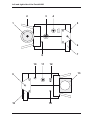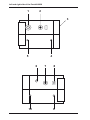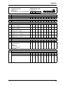
1
Operating Instructions Measurable success by Sewerin equipment Congratulations. You have chosen a quality instrument manufactured by Hermann Sewerin GmbH. Our equipment will provide you with the highest standards of performance, safety and efficiency. They correspond with the national and international guide-lines. Please read and understand the following operating instructions before using the equipment; they will help you to use the instrument quickly and competently. If you have any queries we are available to offer advice and assistance at any time. Yours Hermann Sewerin GmbH Robert-Bosch-Straße 3 33334 Gütersloh, Germany Tel.:+49 5241 934-0 Fax:+49 5241 934-444 www.sewerin.com [email protected] Sewerin Ltd Sewerin USA, LLC Hertfordshire UK Phone: +44 1462-634363 www.sewerin.co.uk [email protected] 13551 W. 43rd Drive, Unit R Golden, CO 80403-7272 Phone: +1 303-424-3611 Fax: +1 303-420-0033 www.sewerin.net [email protected] SEWERIN Sarl SEWERIN IBERIA S.L. 17, rue Ampère - BP 211 67727 HOERDT CEDEX, France Tél. :+33 3 88 68 15 15 Fax :+33 3 88 68 11 77 www.sewerin.fr [email protected] c/ Cañada Real de Merinas, 17 Centro de Negocios „Eisenhower“ Edificio 5; Planta 2 - C 28042 Madrid, España Tel.:+34 91 74807-57 Fax:+34 91 74807-58 www.sewerin.es [email protected] Left and right side of the Portafid M3 2 3 4 5 1 6 7 8 10 11 12 13 9 15 14 Left and right side of the Portafid M3K 1 2 3 5 4 6 10 7 8 9 Operating Instructions PORTAFID® M3 PORTAFID® M3K 11.07.2007 – V1.XXX – 102708 – en For your safety This product may only be operated by appropriately-trained persons who are familiar with the relevant operating manual. It may only be used for its designated purpose, i.e. for industrial and commercial use. Repair work may only be carried out by specialists or by persons who have undergone appropriate training. Any alterations or modifications to the product require the prior approval of Hermann Sewerin GmbH. In the event of unauthorised alterations to the product the manufacturer accepts no liability for damage. Only Hermann Sewerin GmbH accessories may be used with the product. Only spare parts approved by us may be used for repairs. Hermann Sewerin GmbH accepts no liability for damage resulting from non-compliance with the foregoing. The guarantee and liability provisions in the Hermann Sewerin GmbH terms of sale and supply are not extended by the foregoing. We reserve the right to make changes in the context of continued technical development. In addition to these instructions, please comply with generally applicable safety and accident-prevention regulations! Symbols used: CAUTION! This symbol is used to indicate dangers which may either result in hazards for the operators or in severe damage – or even destruction – of the product. Note: This symbol is used to call attention to information and tips which may be helpful and which are exceeding the basic operating procedures. Contents Page 1 PORTAFID M3/M3K models.....................................................1 1.1 Probe systems...........................................................................2 2 Measuring operation................................................................3 2.1 2.2 2.3 2.4 2.5 2.6 2.7 2.8 2.9 Switching on...............................................................................5 Illumination and contrast............................................................7 Alarm signal and volume............................................................7 Alarm-threshold value................................................................8 Switching measuring ranges......................................................8 Zero point adjustment................................................................9 Battery alarm............................................................................10 Switching off.............................................................................10 Pressure reading......................................................................10 3 Charging equipment..............................................................12 4 Inspection, testing and maintenance...................................14 4.1 Testing technique.....................................................................15 5 Adjustment.............................................................................16 6 Technical notes......................................................................22 7 Technical data........................................................................24 8 Accessories............................................................................25 9 Error messages......................................................................26 10 Wearing parts.........................................................................27 Appendix...............................................................................................28 Declaration of Conformity.......................................................................28 Inspection protocol.................................................................................29 1 PORTAFID M3/M3K models 1 PORTAFID M3/M3K models Both gas detectors are suitable for the following purposes: testing underground supply-line piping crossing landfill sites PORTAFID M3 compact device with 0.1 l steel bottle beneath it, for short-term use PORTAFID M3K column device with separate 0.47 l steel bottle and comfortable harness, for an 8-hour day 1 PORTAFID M3/M3K models 1.1 Probe systems Pipes monitoring probes Carpet probe FID Part no.: ZS01-11200 for checking stable surfaces. The sample is drawn into an excrescence in a neoprene mat in contact with the surface with no extraneous emissions. Bell probe FID Part no.: ZS05-10100 for checking unstable and overgrown surfaces. It can be used in confined spaces, e.g. between parked cars or in front gardens. Note: Except with the carpet probe, a probe hose should always be used with a hydrophobic filter 2 Measuring operation 2 Measuring operation Note: Please fold out the PORTAFID M3 illustration inside the front cover. Item Description Function 1 Handwheel opens and closes the fuelgas bottle 2 Stand holds the device in the correct position 3 Cylinder release disconnects the fuelgas bottle 4 Buzzer acoustic warning signal 5 LCD displays gas concentrations and operating status 6, 8 Attachment points for carrying straps 7, 15 Carrying handle transporting the device 9, 14 Attachment points for carrying straps 10 Discharge of gas sample 11 Probe connector connects to the probes described 12 Charger socket connects to chargers 13 Mounting for fuelgas bottle 2 Measuring operation Note: Please fold out the PORTAFID M3K illustration inside the front cover. Item Description Function 1 Fuelgas connection connects to the fuelgas cylinder on the harness 2 Buzzer acoustic warning signal 3 LCD displays gas concentrations and operating status 4, 5 Attachment points for harness 6 Discharge der Gasprobe 7 Probe connector connects to the probes described 8 Charging socket connects to chargers 9, 10 Attachment points for harness 2 Measuring operation 2.1 Switching on Note: When in use the gas detector must always be in the correct position, i.e. with the LCD uppermost . Do not disconnect the PORTAFID M3 fuelgas bottle unless the pressure is less than < 20 bar. PORTAFID M3 open the 0.1 l fuelgas bottle (item 1) by turning to the right PORTAFID M3K open the 0.47 l fuelgas bottle on the harness by turning to the right press the ON/OFF key for about 2 seconds the buzzer (item 4) sounds for about 2 seconds remaining operating hours are displayed in the form of a bar graph (e.g. 5 hours) the built-in pump runs at maximum power the appropriate symbol appears in the LCD (item 5) to enable the pump function to be monitored 2 Messbetrieb only the PORTAFID M3 displays: fuelgas inlet pressure (e.g. 120 BAR) and fuelgas operating time in the form of a bar graph (e.g. 4 hours) display of: fuelgas outlet pressure (e.g. 0,87 BAR) the interval alarm sounds Note: This display appears only if: the fuelgas outlet pressure is outside the set range of 0.95 – 1.10 bar (for how to correct this see “6.0 Technical notes”) the fuelgas bottle is empty (i.e. the cylinder pressure is less than < 10 bar) and needs refilling or replacing. automatic ignition now takes place 2 Measuring operation after ignition wait until the zero point in fresh air has established itself (about 2 – 3 minutes): 0 PPM (after flashing stops) 2.2 Illumination and contrast Repeatedly pressing the Light key switches the LCD illumination on and off after about 4 minutes the illumination automatically switches off simultaneously pressing the Light key and one of the Arrow keys increases or reduces the contrast of the LCD 2.3 Alarm signal and volume Repeatedly pressing the Signal key switches the alarm signal on and off the appropriate symbol appears in or disappears from the LCD (item 5) this enables you to monitor the alarm signal 2 Measuring operation simultaneously pressing the Signal key and one of the Arrow keys increases or reduces the buzzer volume (item 7) 2.4 Alarm-threshold value As long as the Threshold value key is held down the alarm-threshold value (e.g. 10 PPM) flashes in the fullrange analogue display repeatedly pressing one of the Arrow keys while holding down the Threshold value key increases or reduces the alarm-threshold value this value is preserved even when the detector is switched off 2.5 Switching measuring ranges All detectors have an analogue display (above, full range) and a digital display (below); both scales indicate the same concentration (e.g. 70 PPM) the analogue display is a logarithmic scale covering the range: ���������� 0 PPM – 1 ���� %VOL 2 Measuring operation here the display of low concentrations is intensified; the measurement result can be read off from the digital display repeatedly pressing the Zoom key switches between the full and optimum ranges depending on the concentration, switching between the following measurement ranges is automatic: 0 – 10 PPM 0 – 1000 PPM 0 – 100 PPM 0 – 1 %VOL the optimum measurement range in this example is 0 – 100 PPM repeatedly pressing one of the Arrow keys while holding down the Zoom key switches manually to the required display range 2.6 Zero point adjustment If the detector fails to reach its zero point of 0 PPM after flushing with copious fresh air, pressing the Zero point key enables you to adjust it manually the reading display flashes while the adjustment is being carried out measurement cannot be resumed until after the flashing stops 2 Measuring operation 2.7 Battery alarm If the battery symbol appears in the LCD, at least 15 minutes’ operating time remains; after that the detector must be recharged 2.8 Switching off Press the ON/OFF key for about 2 seconds the buzzer (item 4) sounds for about 2 seconds remaining operating hours are displayed in the form of a bar graph (e.g. 5 hours) 2.9 Pressure reading You can display the current cylinder pressure even when the PORTAFID M3 is switched off open the 0.1 l fuelgas bottle (item 1) by turning to the right press the Ignition key 10 2 Measuring operation this displays the: fuel-gas inlet pressure (e.g. 120 BAR) and fuel-gas operating time in the form of a bar graph (e.g. 4 hours) the detector automatically switches off; close the bottle again 11 3 Charging equipment 3 Charging equipment When fully charged the PORTAFID M3 and M3K can be operated for a maximum of 8 hours with the pump running. The gas detectors can be charged in the workshop or in the emergency vehicle. The following connection devices are available: AC/DC adapter M4 100 – 240 V~ Part no.: LD10-10001 Car cable M4 12 V= mounting Part no.: ZL07-10000 with built-in fuse and blade receptacles, for the fix connection to vehicle electrics Car cable M4 12 V= mobile Part no.: ZL07-10100 with built-in fuse and connector for cigarette lighter, for mobile vehicle mounting Car cable M4 24 V= mounting Part no.: ZL09-10000 with voltage transformer and blade receptacles, for the fix connection to vehicle electrics 12 3 Charging equipment Charging Connect the detector (switched off) to a charger and a display of the following type appears: the detector still has 5 operating hours left (= 5 bars) and will take one more hour to be fully recharged the instrument is quickly chargeable and the maximum charging time is approx. 2.5 hours + when it is fully charged all the bars are visible and the number display disappears the detector can be left connected to the charger until the next time it is needed Note: Due to the fast-charging option, the admissible temperature range is 0 °C – +40 °C during charging. Spontaneous discharge If the detector is not connected to the charger when switched off, the nickel-metal-hydride accu spontaneously discharges, thus reducing the available operating hours. After a maximum of 30 days the detector indicator shows that there are no operating hours left, and it must be recharged. 13 4 Inspection, testing and maintenance 4 Inspection, testing and maintenance DVGW work sheet G 465-4 requires detectors to be inspected, tested and maintained. Sensitivity testing may be necessary several times a day, according to G 465-1, depending on the circumstances - particularly with gas detectors used to monitor mains pipes. Inspection must be carried out up to six times a year, depending on frequency of use - and at any rate at least once a year. The following items must be tested: detector condition pump power battery condition zero point intake channel sensitivity (with test gas) Test report Test results must be recorded. A specimen form will be found on the last page of this manual. Servicing and maintenance DVGW work sheet G 465-4 specifies that servicing and maintenance of the detectors may be carried out only by the following persons: the SEWERIN Service or an expert authorised by SEWERIN. Servicing must be carried out at least once a year. The next scheduled date must be entered on the inspection sticker attached to the detector (month/year). After servicing a certificate must be completed. 14 4 Inspection, testing and maintenance 4.1 Testing technique The test case PPM complete is used to check and calibrate the sensitivity and pump capacity within the ppm range. Testing can be effected with carpet or bell probes. Test case PPM complete Part no.: ZP03-12001 test set SPE ppm incl. flowmeter (0 – 80l/h) hard-shelled case, orange coloured, with foam inlet 0.4 l test gas bottle, 10 ppm CH4 (methane) in synthetic air, pressure 100 – 150 bar pressure regulator and manometer test plate for probe testing and connection hoses 15 5 Adjustment 5 Adjustment The PORTAFID M3 and PORTAFID M3K detectors are factoryset to the 10 ppm measuring range. You can adjust each of the ranges using appropriate test gases (one for each range). Testing procedure Connect your detector to the test set. now press this combination of buttons simultaneously First Display - version number/zero point Once the number of available operating hours has been displayed the detector is in adjustment mode: the software version number (e.g. V1.0) is displayed and the pump runs at maximum power the reading display flashes until the zero point of the FID system has been automatically established once the zero point has been set, press the Arrow-up key to move to the next display 16 5 Adjustment 10 ppm adjustment Now release the 10 ppm methane CH4 test gas from the SPE ppm test set. wait until the display has stabilised confirm the adjustment with the ON/OFF key (OK appears in the LCD) turn off the test-gas feed press the Arrow-up key to move to the next display 100 ppm adjustment Now release the 100 ppm methane CH4 test gas from the SPE ppm test set. wait until the display has stabilised confirm the adjustment with the ON/OFF key (OK appears in the LCD) turn off the test-gas feed press the Arrow-up key to move to the next display 17 5 Adjustment 1000 ppm adjustment Now release the 1000 ppm methane CH4 test gas from the SPE ppm test set. wait until the display has stabilised confirm the adjustment with the ON/OFF key (OK appears in the LCD) turn off the test-gas feed press the Arrow-up key to move to the next display 1.00 vol.% adjustment Now release the 1.00 vol.% methane CH4 test gas from the SPE ppm test set. wait until the display has stabilised confirm the adjustment with the ON/OFF key (OK appears in the LCD) turn off the test-gas feed press the Arrow-up key to move to the next display 18 5 Adjustment Vol.% range language By repeatedly pressing the on/off key you can choose between the following displays in the vol.% range: %VOL - concentration display in vol.% (German/English) %GAZ - concentration display in vol.% (French) confirm the display, e.g. %VOL, with the on/off key (OK appears in the LCD) this setting is retained even when the detector is switched off press the Arrow-up key to move to the next display 19 5 Adjustment 10 PPM sensitivity Whether synthetic or fresh air is used for the zero-point adjustment, you must always achieve sensitivity of > 5 ppm when using 10 ppm methane CH4 test gas. To this end you can select from the following amplification ratios in the 10 ppm range by repeatedly pressing the on/ off key switch: 1,0 x 10 PPM - 100 % amplification 1,2 x 10 PPM - 120 % amplification 1,5 x 10 PPM - 150 % amplification (factory setting) confirm the selected amplification (e.g. 1.5 x 10 PPM) with the on/off key press the Arrow-up key to move to the next display 20 5 Adjustment LCD check With this function you can check whether all elements of the LCD are operating normally. confirm the LCD check with the on/off key press the Arrow-up key to return to the first display Leave adjustment mode (possible only in the first display) simultaneously press both Arrow keys to return to normal measuring operation or press the on/off key to switch the detector off 21 6 Technical notes 6 Technical notes Delayed-action indicator To facilitate the comparison of different gas concentrations, the maximum value is displayed by a flashing delayed-action indicator. this remains in the LCD (item 5) for about 4 minutes unless updated by a higher concentration Fine dust filters There are fine dust filters in the screw-on probe connector (item 3) and in most probes. The filters can be cleaned by tapping or blowing to remove the dust. Note: After cleaning the filters must be replaced in the same position as before. Heavily-soiled filters should be replaced by new ones (accessories). Adjusting the outlet pressure PORTAFID M3: the outlet pressure is adjusted on the underside of the detector with an Allen key (supplied). PORTAFID M3K: the outlet pressure is adjusted at the pressure gauge on the harness. 22 6 Technical notes Automatic alarm reset If the alarm threshold is exceeded the acoustic alarm is set off. It can be switched off with the Signal key. After about 2 minutes it is automatically reset. Cleaning No solvents, benzines or similar substances may be used to clean the detectors. Oxygen concentration The detectors are electrically safe to use in an oxygen concentration of up to 21 vol.%. At oxygen concentrations of < 16.0 vol.%, the H2 flame might cease (F 110). 23 7 Technical Data 7 Technical data Detector types PORTAFID M3 PORTAFID M3K Calibration Methane (CH4) Measuring range 0 – 10,000 ppm = 1 vol.% Measurement range definition 10 ppm 100 ppm 1000 ppm 1 vol.% - 1 ppm steps - 2 ppm steps - 20 ppm steps - 0.02 vol.% steps Measuring error ≤1% Measurement system Flame-Ionisation-Detector Pump power > 50 l/h and >150 mbar Alarm threshold 3 ppm (variable) Operating time Electrical: 8 hours Fuel gas: 5 hours (0.1 l) 25 hours (0.47 l) (at 150 bar cylinder pressure) 24 Power supply NiMh-battery, rechargeable Dimensions (W x H x D) and weight PORTAFID M3 270 x 185 x 105 mm/3.800 g PORTAFID M3K (without bottle) 270 x 140 x 105 mm/1.700 g Operating temperature -10 °C to +40 °C Storage temperature -25 °C to +70 °C Humidity range 5 % r.h to 90 % r.h. (non-condensing) Pressure range 900 h Pa bis 1100 h Pa Charging time 2.5 hours Charging temperature 0 °C to +40 °C 8 Accessories 8 Accessories Charging technique AC/DC adapter M4 100 – 240 V~/12 V=, Car cable M4 12 V or 24 V Probe systems carpet probe and bell probe for Network Survey Probe hose with hydrophobic filter and quick connect Plunger bar for making probe holes manually handle insulated to 10 kV working lengths 625 mm, 1025 mm and 1325 mm Testing technique Test case PPM complete Test set SPE ppm System case with foam lining and compartments for accessories Carrying systems PORTAFID M3: cross-straps, PORTAFID M3K: harness 25 9 Error messages 9 Error messages The detectors automatically identify errors and show the error code in the LCD (item 5) Error code Cause and remedy F10 – F14................Adjustment errors in the PPM range, check testgas or repeat adjustment F50 – F56................Component errors, remedy: contact Sewerin service F100........................pump power inadequate, e.g. because ambient temperatures are too low switch detector off and on again, check filters in detector and probes F110.........................flame extinguished excessive gas concentration in the combustion chamber flush out and manually reignite F200........................AC/DC adapter defect F201........................Temperature during charge out of admissible range Note: If any other error codes are displayed, please contact the SEWERIN Service. 26 10 Wearing parts 10 Wearing parts Fine dust filter in the detectors’ probe connectors (item 11 or 7) Hose filter in the carpet probe and probe hose Probe filter inlet in the bell probe Hydrophobic filter in the 1 m, 2 m and 6 m probe hoses Neoprene mat for the carpet probe 27 Appendix 28 Appendix Inspection protocol Calibration: Serial Number : (e.g.: 003 01 0001) PORTAFID® M3 / M3K Methane CH4 15.01.2009 1.0 Device status 1.1 - Status correct (e.g.: Y / N) 1.2 - Remaining operating hours (e.g.: 5 h) 2.0 Pump check 2.1 - Pump error F100 in seal 3.0 PPM measuring range 3.1 Zero point - Fresh air reading 3.2 Test gas 10 ppm CH 4 - Display > 10 ppm 3.3 Test gas 100 ppm CH 4 - Display 90 – 110 ppm 3.4 Test gas 1.000 ppm CH 4 - Display 900 – 1.100 ppm 3.5 Test gas 1.00 vol.% CH 4 - Display 0.90 – 1.10 vol.% 4.0 Alarm function 4.1 - Audible alarm signal (e.g.: Y / N) 5.0 Observations - Housing broken - Repair - Adjustment - Factory inspection - or the like 6.0 Test - Day - Month - Year - Signature 29 11.07.2007 – 102708 – en Hermann Sewerin GmbH Robert-Bosch-Straße 3 · 33334 Gütersloh · Germany Telefon +49 5241 934-0 · Telefax +49 5241 934-444 www.sewerin.com · [email protected]