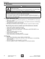
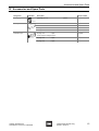
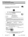
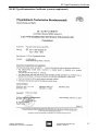
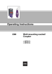
1
Operating Instructions
Wall-Mounted Socket,
Plug
> 8570/11, 8570/12
Contents
1
Contents
1
2
3
4
5
6
7
8
9
10
11
12
13
14
2
Contents ................................................................................................................2
General Information ...............................................................................................2
General Notes Regarding Safety ..........................................................................3
Intended Area of Application .................................................................................4
Technical Data ......................................................................................................5
Transport, Storage and Disposal ...........................................................................9
Assembly .............................................................................................................10
Installation ...........................................................................................................11
Commissioning ....................................................................................................13
Operation .............................................................................................................13
Maintenance ........................................................................................................14
Accessories and Spare Parts .............................................................................15
EC Type Examination Certificate ........................................................................16
EC Declaration of Conformity ..............................................................................18
General Information
2.1 Manufacturer
R. STAHL Schaltgeräte GmbH
Am Bahnhof 30
74638 Waldenburg, Germany
Phone:
Fax:
Internet:
+49 7942 943-0
+49 7942 943-4333
www.stahl.de
2.2 Information Regarding these Operating Instructions
ID NO.:
150646 / 8570601300
Publication Code:
S-BA-8570/11/12-04-en-17/06/2009
We reserve the right to make technical changes without notice.
2.3 Symbols Used
X
Z
X
)
Action request:
Describes actions to be carried out by the user.
Reaction sign:
Describes the results or the reactions to the actions taken.
Bullet
Information sign:
Describes the notes and recommendations.
Warning sign:
Danger from energised parts!
Warning sign:
Danger due to an explosive atmosphere!
2
Wall-Mounted Socket, Plug
8570/11, 8570/12
150646 / 8570601300
S-BA-8570/11/12-04-en-17/06/2009
General Notes Regarding Safety
3
General Notes Regarding Safety
3.1 Safety instructions for installation and operating personnel
The operating instructions contain basic safety instructions which are to be observed
during installation, operation and maintenance. Non-observance can lead to
endangerment of persons, plant and the environment.
WARNING
Risk due to unauthorised work being performed on the device!
Z There is a risk of injury to persons and damage to equipment.
X Assembly, installation, commissioning, operation and maintenance must only be
performed by personnel who are both authorised and suitably trained for this purpose.
Before assembly/commissioning:
X Read through the operating instructions.
X Give adequate training to the assembly and operating personnel.
X Ensure that the contents of the operating instructions are fully understood by
the personnel in charge.
X The national installation and assembly regulations (e.g. IEC/EN 60079-14) apply.
When operating the device:
X Ensure the operating instructions are made available on location at all times.
X Observe safety instructions.
X Observe national safety and accident prevention regulations.
X Only run the device according to its performance data.
X Servicing/maintenance or repair work which are not described in the operating
instructions must not be performed without prior agreement with the manufacturer.
X Any damage may render explosion protection null and void.
X No changes to the devices or components impairing their explosion protection are
permitted.
X Install and use the device only if it is undamaged, dry and clean.
If you have questions:
X Contact the manufacturer.
3.2 Warning notes
Warnings are sub-divided in these operating instructions according to the following
scheme:
WARNING
Type and source of the danger!
Z Possible consequences.
X Measures to avoid danger.
They are always identified by the signalling word “WARNING“ and sometimes also have
a symbol which is specific to the danger involved.
150646 / 8570601300
S-BA-8570/11/12-04-en-17/06/2009
Wall-Mounted Socket, Plug
8570/11, 8570/12
3
Intended Area of Application
3.3 Conformity to Standards
The wall-mounted socket 8570/11 and plug 8570/12 comply with the following directives
and standards:
X
X
X
X
4
Directive 94/9/EC
IEC/EN 60079-0, IEC 60079-1, IEC/EN 60079-7, IEC/EN 60079-11
IEC/EN 61241-1
IEC/EN 60947-3, IEC/EN 60947-4-1, IEC/EN 60309, IEC/EN 60529
Intended Area of Application
The wall-mounted socket 8570/11 and plug 8570/12 are explosion protected electrical
devices.
They serve the connection of portable and fixed electrical devices and the connection of
cable or circuits respectively, in areas where an explosion hazard exists.
They have an area classification for use in Zones 1, 2, 21 and 22.
WARNING
Only use the device for its intended purpose!
Z Otherwise, the manufacturer’s liability and warranty expire.
X The device may only be used under the operating conditions described in these
operating instructions.
X The device may only be used in hazardous areas according to these operating
instructions.
4
Wall-Mounted Socket, Plug
8570/11, 8570/12
150646 / 8570601300
S-BA-8570/11/12-04-en-17/06/2009
Technical Data
5
Technical Data
Socket
8570/11 (16 A)
Explosion protection
Gas explosion protection
ATEX
E II 2 G Ex de IIC T6
Special version with intrinsically safe auxiliary contacts
E II 2 G Ex de [ia] IIC T6
IECEx
Ex de IIC T6
Ex de [ia] IIC T6
Dust explosion protection
ATEX
E II 2 D Ex tD A21 IP66 T80 °C
IECEx
Ex tD A21 IP66 T80 °C
Ambient temperature
- 30 °C ... + 55 °C
- 50 °C on request (internal lubrication with silicone grease)
Certificates
Gas explosion protection
ATEX
PTB 03 ATEX 1227
IECEx
IECEx PTB 05.0023
Dust explosion protection
ATEX
PTB 03 ATEX 1227
IECEx
IECEx PTB 05.0023
Marine certification
GL 26 296 - 05 HH (Germanischer Lloyd)
Number of pins
2 P + ¿, 3 P + ¿, 3 P + N + ¿
Auxiliary contacts
optionally (2 pieces), ON - delayed, OFF- advanced
Rated operational voltage
Main contacts
max. 690 V AC
max. 110 V DC
Auxiliary contacts
max. 500 V AC / 110 V DC
Frequency
0 Hz ... 60 Hz
Voltage tolerance
- 10% ... + 6%
Rated operational current
Main contacts
16 A
Auxiliary contacts
max. 6 A
Rated operational power
Main contacts:
AC 3
690 V
16 A
4 kW
7.5 kW
11 kW
220 V / 230 V / 240 V
380 V / 400 V / 415 V / 500 V
600 V / 690 V
DC1
110 V
16 A
Auxiliary contacts:
AC 15
500 V
max. 1250 VA
AC 15
230 V
max. 1380 VA
AC 12
500 V
max. 3000 VA
DC 13
110 V
110 W
Back-up fuse
without thermal protection
16 A gL
with thermal protection
35 A gL
Operating handle
Actuator is lockable in 0 and I position
150646 / 8570601300
S-BA-8570/11/12-04-en-17/06/2009
Wall-Mounted Socket, Plug
8570/11, 8570/12
5
Technical Data
Material
Enclosure
Polyamide, glass fibre reinforced
Degree of protection
IP66
Type of connection
Screw terminals
Connection cross-section
Main contacts
12 x 1.5 mm2 ... 6 mm2 solid
2 x 1.5 mm2 ... 4 mm2 finely-stranded
Auxiliary contacts
2 x 0.5 mm2 ... 2.5 mm2 solid, finely-stranded
Cable entries
Stopping plug
1 x M 25 x 1.5
Cable gland
1 x M 25 x 1.5
Cable dia. range
7 mm ... 17 mm
Special version
Cable entries on top and rear side.
1 x M25 metal cable gland (see R. STAHL Catalogue, Chapter 12).
Weight
8570/11-3
1.12 kg
8570/11-4
1.35 kg
8570/11-5
1.45 kg
8570/12-3
0.31 kg
8570/12-4
0.38 kg
8570/12-5
0.43 kg
Service life
5000 switching cycles (electrical and mechanical)
Tightening torque
Terminals
max. 1.2 Nm
Connection chamber
cover
max. 1.8 Nm
Plug
8570/12
Further technical data
see sockets 8570/11
Cable connection
Cable dia. range
8 mm ... 20 mm
Tightening torque
Plug enclosure
6
max. 1.0 Nm
Wall-Mounted Socket, Plug
8570/11, 8570/12
150646 / 8570601300
S-BA-8570/11/12-04-en-17/06/2009
Technical Data
Dimension drawings (all dimensions in mm) - subject to alterations
10338E00
8570/11-3..
10333E00
8570/11-4.. and 8570/11-5..
Type
A
B
8570/12-3..
16 A, 2 P + ø
43.5
76
8570/12-4..
16 A, 3 P + ø
49
89
8570/12-5..
16 A, 3 P + N + ø
56.5
92
10337E00
8570/12-..
150646 / 8570601300
S-BA-8570/11/12-04-en-17/06/2009
Wall-Mounted Socket, Plug
8570/11, 8570/12
7
Technical Data
Position of the protective earth (PE) contact
Position: clock-hour position; View: front face of the socket
Example: clock-hour position
06190E00
250 V = 6 o’clock
02395E00
Contact layout and terminal markings
2P+¿
3P+¿
06190E00
8570/11-3..
3P+N+¿
06556E00
8570/11-4..
06555E00
8570/11-5..
Contact layout and terminal markings in the 6 o’clock position (view from the front face of shrouded socket onto the contacts).
8
Wall-Mounted Socket, Plug
8570/11, 8570/12
150646 / 8570601300
S-BA-8570/11/12-04-en-17/06/2009
Transport, Storage and Disposal
Contact layout and identification colour and terminal markings
Number of poles
Frequency [Hz]
Voltage [V]
Identification colour
Position of the PE
contact
8570/..-3..
2P + ¿
50 - 60
110 - 130
yellow
4 o’clock
50 - 60
200 - 250
blue
6 o’clock
60
277
light grey
5 o’clock
50 - 60
480 - 500
black
7 o’clock
> 300 - 500
8570/..-4..
3P+¿
8570/..-5..
3P+N+¿
1)
2)
> 50
green
2 o’clock
DC
> 50 - 110
light grey
3 o’clock
50 - 60
200 - 250
blue
9 o’clock
50 - 60
380 - 415
red
6 o’clock
1)
60
440 - 460
red
11 o’clock
50 - 60
480 - 500
black
7 o’clock
50 - 60
600 - 690
black
5 o’clock
100 - 300 2)
> 50
green
10 o’clock
50 - 60
120/208 - 144/250
blue
9 o’clock
50 - 60
200/346 - 240/415
red
6 o’clock
50 - 60
277/480 - 288/500
black
7 o’clock
50 - 60
347/600 - 400/690
black
5 o’clock
red
11 o’clock
60
250/440 - 265/460
1)
Identification colour and layout in relation to the keyway for the various voltages and frequencies, in accordance with IEC/EN 60309-2
1) Primarily for installation on board ships
2) Frequencies ) 100 Hz lead to increased heating behaviour. This must be compensated for by a max. ambient temperature
of ( 40 °C, temperature class T5 or a reduction of current to 12 A.
6
Transport, Storage and Disposal
Transport
X Shock-free in its original carton, do not drop, handle carefully.
Storage
X Store in a dry place in its original packaging.
X Storage temperature range: - 55 °C ... + 80 °C
Disposal
X Ensure environmentally friendly disposal of all components according to legal
regulations.
150646 / 8570601300
S-BA-8570/11/12-04-en-17/06/2009
Wall-Mounted Socket, Plug
8570/11, 8570/12
9
Assembly
7
Assembly
7.1 Assembly, wall-mounted socket, type 8570/11-...
)
If exposed to the elements, the casing must be provided with a protective
canopy or wall.
Position for use: Hinged cover down, connection chamber up
X Fasten the wall-mounted socket, in a vertical position, to a flat wall, using four screws.
)
The securing holes are elongated. This allows the casing to be adjusted both
vertically and horizontally.
Assembling the auxiliary contacts
11203E00
X Open enclosure.
X Insert the auxiliary contacts into the left or right receptacle (until they engage).
Both can be fitted if necessary.
X Close the casing.
7.2 Assembly, plug type 8570/12-...
)
To prevent dirt from contaminating the contacts, a compatible sealing cap can
be used (see Chapter 12, “Accessories and Spare Parts“).
Position for use: When the plug is disconnected, it must be hung with the pins pointing
downwards.
10
Wall-Mounted Socket, Plug
8570/11, 8570/12
150646 / 8570601300
S-BA-8570/11/12-04-en-17/06/2009
Installation
8
Installation
WARNING
Danger from live parts!
Z Risk serious injury.
X All connections and wiring must be disconnected from the power supply.
X Secure the connections against unauthorised re-connection.
WARNING
Danger of explosion!
Z There is a risk of injury to persons and material damage.
X Choose a suitable conductor, so that the maximum permissible
conductor temperature is not exceeded.
X If using wire end ferrules, fit these in a gastight manner using the
appropriate tool.
X Only use 2-core cables, without screen braiding in intrinsically safe circuits.
Observe the insulating capacity and spacing between intrinsically safe and
non-intrinsically safe circuits, in accordance with IEC/EN 60079-11 and
IEC/EN 60079-14, section 12.
X Only use separately tested cable entry glands and sealing plugs, which
have an EC-Type examination certificate.
X Conductor insulation must reach right to the terminal.
X The conductor must not be damaged (e.g. notched) when stripping the
insulation.
X Always connect the protective earth conductor.
8.1 Installation wall-mounted socket, type 8570/11
)
Two conductors can be clamped under a single terminal. Conductor material
and cross sectional area must be identical.The conductors can be connected,
without special preparatory measures.
Dimensions [mm]
A
B
Main contacts
180
10
Auxiliary contacts
180
6
Auxiliary contacts Ex i
20
6
X Open enclosure.
X Pass the cable through the cable entry into the connection chamber.
X Insert the conductors into the corresponding terminals and clamp them (tightening
torque: see Chapter 5, “Technical Data“). The stripped ends of the wire must be fully
beneath the terminal clamping plate.
X Align the wires (clamped ends must be relieved of strain).
X Tighten the cable gland(s).
X Close enclosures. Tightening torque see Chapter 5 Technical Data.
150646 / 8570601300
S-BA-8570/11/12-04-en-17/06/2009
Wall-Mounted Socket, Plug
8570/11, 8570/12
11
Installation
Installing auxiliary contacts
11202E00
X Open enclosures.
X Pass the cable through the cable entry into the connection chamber.
X Unlock screwless terminals with a slotted screwdriver 0.6x3.5 mm - ISO 2380 (2) and secure
stripped wire ends. The stripped wire ends must be entirely placed under the clamp plate.
X Align the wires (clamped ends must be relieved of strain).
X Tighten the cable entry gland(s).
X Close enclosures. Tightening torque see Chapter 5 Technical Data.
8.2 Installation, plug, type 8570/12-...
11222E00
X
X
X
X
X
X
X
X
X
Screw the cable gland (1) off and remove the dust exclusion plate (2).
Remove the pressure ring (3) and seal (4).
Remove the shell securing screws (5) and remove the plug shell (6).
Insert the cable (max. 4 mm2) through the cable gland (1), pressure ring (3) and
seal (4). If necessary, cut the seal out to match the cable diameter.
Open the strain relief (7) and swivel it by 90°.
Insert stripped cable ends in corresponding terminal and clamp (1.2 Nm). The stripped wire
ends must be entirely placed under the clamp plate.
The stripped ends of the wire must be fully within the terminal clamp.
Swivel the strain relief back into position and fit it to the cable. The clamped end must be
relieved of strain.
Fit the plug shell, insert and tighten screws (tightening torque: see Chapter 5, "Technical
Data").
X Press the seal into the plug shell, apply the pressure ring and screw the cable gland
tight.
12
Wall-Mounted Socket, Plug
8570/11, 8570/12
150646 / 8570601300
S-BA-8570/11/12-04-en-17/06/2009
Commissioning
9
Commissioning
Before commissioning
X
X
X
X
X
X
X
X
X
Check for correct assembly and installation.
Inspect the casing for damage.
Remove foreign objects if necessary.
Clean the connection chamber if necessary.
Check that the cables enter the casing correctly.
Check-tighten all screws, bolts and nuts.
Check-tighten all cable entry glands and sealing plugs.
Observe the mains voltage.
Seal all cable entries, which are not used, with plugs certified in accordance with
directive 94/9/EC and seal all holes, which are not used, with sealing plugs certified in
accordance with directive 94/9/EC.
X Only operate if fully assembled.
10 Operation
)
The wall-mounted socket and plug must only be operated if fully assembled.
10.1 Operation, wall-mounted socket, type 8570/11-...
)
X The wall-mounted socket switch can only be operated if a plug is inserted.
X When the plug is disconnected, lock the hinged cover with the bayonet
ring.
Only type 8570/12 and 8575/12 plugs, manufactured by R. STAHL, must be used.
10.2 Operation, plug, type 8570/12-...
If a short circuit occurs in the circuit, to which the plug is connected, check the function of
the plug.
The plug can be operated together with the following products manufactured by
R. STAHL.
X Wall-mounted sockets 8570/11, 8575/11, 8575/13, 7570/11 and 7575/11
X Flange sockets 8570/15 and 8575/15
X Coupling sockets 8575/14 and 8575/16
The plug fits industrial sockets (compliant with CEE standard).
150646 / 8570601300
S-BA-8570/11/12-04-en-17/06/2009
Wall-Mounted Socket, Plug
8570/11, 8570/12
13
Maintenance
11 Maintenance
WARNING
Danger from live parts!
Z Risk serious injury.
X All connections and wiring must be disconnected from the power supply.
X Secure the connections against unauthorised re-connection.
WARNING
Danger through defective switch contacts!
Z There is a risk of injury to persons and material damage.
X The complete flange socket must always be replaced, if a short circuit occurs
in the switch's main circuit, as the state of the switch contacts of hermetically sealed
devices can not be determined.
11.1 Regular Maintenance Work
X Refer to the corresponding national regulations (e.g. IEC/EN 60079-17) for the type
and scope of tests.
X The maintenance intervals must be chosen, such that the occurrence of deficiencies,
anticipated in the system, can be avoided.
X The plug must be disconnected at regular intervals, to prevent contact corrosion.
The following items must be checked as part of the maintenance schedule:
X Check that no cable connections are loose.
X Inspect the casing for visible signs of damage.
X Check that the permitted temperatures, in accordance with IEC/EN 60079-0, are
adhered to.
X Check that female contacts are clean.
X Inspect seals for damage.
X Check that the device functions correctly.
X Check that surfaces of the plug pins are not damaged.
11.2 Cleaning
X Clean with a cloth, brush, vacuum cleaner or similar items.
X When cleaning with a damp cloth use water or mild, non-abrasive, non-scratching
cleaning agents.
X Never use aggressive cleaning agents or solvents.
X Avoid the ingress of water or cleaning agents into the female contacts.
14
Wall-Mounted Socket, Plug
8570/11, 8570/12
150646 / 8570601300
S-BA-8570/11/12-04-en-17/06/2009
Accessories and Spare Parts
12 Accessories and Spare Parts
Designation
Illustration
Description
Order number
8290/3-M 25 x 1.5
Sealing plugs
1 piece
143524
04840E00
Auxiliary contacts
10341E00
1 NO
150682
1 NC
150680
1 NO, gold contact
150686
1 NC, gold contact
150684
for plug 16 A
Protection caps
3-pole
150496
not for extra-low voltage version
05365E00
150646 / 8570601300
S-BA-8570/11/12-04-en-17/06/2009
for plug 16 A
4-pole
150510
for plug 16 A
5-pole
150520
Wall-Mounted Socket, Plug
8570/11, 8570/12
15
EC Type Examination Certificate
13 EC Type Examination Certificate
13.1 EC Type Examination Certificate (Page 1)
16
Wall-Mounted Socket, Plug
8570/11, 8570/12
150646 / 8570601300
S-BA-8570/11/12-04-en-17/06/2009
EC Type Examination Certificate
13.2 EC Type Examination Certificate (current supplement)
150646 / 8570601300
S-BA-8570/11/12-04-en-17/06/2009
Wall-Mounted Socket, Plug
8570/11, 8570/12
17
EC Declaration of Conformity
14 EC Declaration of Conformity
18
Wall-Mounted Socket, Plug
8570/11, 8570/12
150646 / 8570601300
S-BA-8570/11/12-04-en-17/06/2009
150646 / 8570601300
S-BA-8570/11/12-04-en-17/06/2009