1
Function module
FM443
solar module
For users
6 720 615 870 - 03/2008 GB/IE
Operating Instructions
Read carefully
before use
Contents
1
Safety
1.1
1.2
1.3
1.4
1.5
1.6
2
. . . . . . . . . . . . . . . . . . . . . . . . . . . . . . . . . . . . . . . . 3
About these instructions . . . . . . .
Correct use . . . . . . . . . . . . . . . .
Standards and guidelines/directives
Symbol key . . . . . . . . . . . . . . . .
Please observe these notes . . . . . .
Disposal . . . . . . . . . . . . . . . . .
Product description .
2.1
. . . . . . . . . . . . . . . . . . 3
. . . . . . . . . . . . . . . . . . 3
. . . . . . . . . . . . . . . . . . 3
. . . . . . . . . . . . . . . . . . 4
. . . . . . . . . . . . . . . . . . 5
. . . . . . . . . . . . . . . . . . 5
. . . . . . . . . . . . . . . . . . . . . . . . . . . . . 6
Manual switch positions . . . . . . . . . . . . . . . . . . . . . . . . . . 8
2.1.1 Manual switch (solar circuit 1) . . . . . . . . . . . . . . . . . . . . . 8
2.1.2 Manual switch (solar circuit selection) . . . . . . . . . . . . . . . . . 9
3
The FM443 functions .
3.1
3.2
4
2
. . . . . . . . . . . . . . . . . . . . . . . . . . . . 10
Changing operating mode. . . . . . . . . . . . . . . . . . . . . . . . . 10
Scanning operating values . . . . . . . . . . . . . . . . . . . . . . . . 12
Troubleshooting
. . . . . . . . . . . . . . . . . . . . . . . . . . . . . . . . 14
FM443 function module - Subject to technical modifications.
Safety
1
Safety
1.1
About these instructions
1
This chapter contains general safety instructions that you should
observe when operating the FM443 function module.
Also closely observe the further safety instructions that you will find
in other chapters of these operating instructions. Carefully read the
safety instructions before commencing the following measures.
Severe injury and even death, as well as damage to property and
environmental damage, may follow if you ignore safety
instructions.
1.2
Correct use
You can fit the FM443 function module into control units that are
part of the Logamatic 4000 control system.
1.3
Standards and guidelines/directives
The design and operation of this product conform to European
Directives and the supplementary national requirements.
Its conformity is demonstrated by the CE designation.
You can view the Declaration of Conformity on the internet
at www.buderus.de/konfo or request a copy from your local
Buderus sales office.
FM443 function module - Subject to technical modifications.
3
1
1.4
Safety
Symbol key
Two levels of danger are identified and signalled by the following
terms:
RISK TO LIFE
Identifies possible risks associated with a product that might lead
to serious injury or death if appropriate care is not taken.
WARNING!
RISK OF INJURY/SYSTEM DAMAGE
CAUTION!
Indicates a potentially dangerous situation which could lead to
minor or moderately serious injuries or to damage to property.
USER INFORMATION
User tips for the optimum utilisation and setting of the appliance
plus useful information.
4
FM443 function module - Subject to technical modifications.
Safety
1.5
1
Please observe these notes
The FM443 function module has been designed and built in
accordance with currently recognised standards and safety
requirements.
However, damage to property resulting from inappropriate
operation cannot be completely prevented.
Read these operating instructions carefully before you attempt
to operate the FM443 function module.
RISK TO LIFE
from electric shock.
WARNING!
z Ensure that all electrical work is carried out by an authorised
electrician.
RISK OF INJURY/SYSTEM DAMAGE
from operator error.
CAUTION!
Operator errors can result in injury and/or damage to property.
z Ensure that children never operate the appliance
unsupervised or play with it.
z Ensure that only personnel able to operate the appliance
correctly have access to it.
1.6
Disposal
z Electronic components must not be disposed of with
general domestic waste.
Dispose of old modules correctly through an authorised
disposal site.
FM443 function module - Subject to technical modifications.
5
2
2
Product description
Product description
The FM443 function module is exclusively designed for use
in the modular Logamatic 4000 control system.
Using the FM443 function module, you can regulate one solar
thermal system with one or two solar consumers (e.g. cylinders).
Installing the FM443 function module makes the following
functions available:
6
–
Changing the solar control unit operating mode
–
Requesting operating values from the solar consumers "1"
or "2", from the heat meter and the collector array
–
Scanning the yield over recent days, weeks and years
FM443 function module - Subject to technical modifications.
Product description
2
6
7
8
9
5
10
4
11
3
2
1
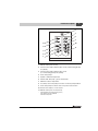
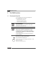
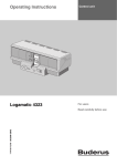
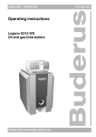
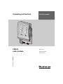
Fig. 1
Front panel – FM443 function module
1
Manual switch (solar circuit 1)
2
"Diverter valve" LED for buffer bypass circuit (central heating backup
via cylinder)
3
"Diverter valve" LED for buffer bypass circuit
(no central heating backup via cylinder)
4
Solar circuit pump 1*
5
Cylinder 1 maximum temperature
6
"Module fault" LED (red) – general module fault
7
Maximum collector temperature
8
Secondary solar circuit pump 2 or transfer or transfer pump enabled*
9
Solar circuit pump 2 or diverter valve 2 in position solar circuit 2*
10 Diverter valve in place of solar circuit 1
11 Manual switch (solar circuit selection)
*
LED constantly ON: Pump running (100 %)
LED "flickers": Pump modulates
LED OFF: Pump OFF
FM443 function module - Subject to technical modifications.
7
2
2.1
Product description
Manual switch positions
SYSTEM DAMAGE
CAUTION!
Incorrect use of switch positions 0 and 3 can damage the solar
thermal system, and may even destroy individual system
components.
z Ensure that the "AUT" switch position is always set.
The various positions of the manual switch have different effects
on the solar circuit or the two solar consumers.
USER INFORMATION
The switches should normally be in the "AUT" position.
Positions 0 and 3 are special settings reserved for qualified
personnel only.
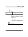
2.1.1
Manual switch (solar circuit 1)
Position
Effect
Solar circuit 1 (solar circuit pump 1) and bypass
(diverter valve) are switched off.
Solar circuit 1 and bypass are in automatic mode –
this is the standard setting.
Manual mode is enabled.
Solar circuit pump 1 is switched on. The bypass is
not being controlled.
Tab. 1
8
Switch positions
FM443 function module - Subject to technical modifications.
Product description
2.1.2
2
Manual switch (solar circuit selection)
Position
Effect
Solar circuit selection is switched off.
The FM443 (solar) function module is in automatic
mode – this is the standard setting.
When there is appropriate solar yield, only solar
consumer "2" (solar circuit 2) is heated.
Automatic changeover is disabled.
When there is appropriate solar yield, only solar
consumer "1" (solar circuit 1) is heated.
Automatic changeover is disabled.
Tab. 2
Switch positions
USER INFORMATION
If the manual switch is not in automatic mode, a message
to that effect appears on the MEC2 programming unit,
and the "Module fault" LED on the module illuminates.
Notify your heating contractor.
FM443 function module - Subject to technical modifications.
9
3
The FM443 functions
3
The FM443 functions
3.1
Changing operating mode
You can change the solar control unit operating mode.
The operating modes are as follows:
–
Manual ON ("Day mode" key)
–
Manual OFF ("Night mode" key)
–
Automatic operation ("AUT" key)
USER INFORMATION
The collector protection is ensured with the "Manual ON"
operating mode ("Day mode" key).
USER INFORMATION
When the flap on the MEC2 programming unit is closed
it will generally indicate to which heating circuit the MEC2
programming unit is assigned. If no heating circuit is assigned
to the MEC2 programming unit, the lowest installed heating
circuit is always shown.
For further details, please see the technical documentation
for your control unit.
Open the flap of the MEC2 programming unit.
Press and hold down "heating circuit".
Turn the rotary selector until "Heating circuit selection – solar"
appears in the display.
Release the "Heating circuit" key.
10
FM443 function module - Subject to technical modifications.
The FM443 functions
3
Different operating modes
Press manual ON ("Day mode" key) to set the solar control
unit to "always on".
Press the "AUT" key to set the solar control to automatic.
Press manual OFF ("Night mode" key) to switch off the solar
control unit.
Operating mode
Input range
Factory setting
Automatic
OFF
ON
Automatic
Manual ON
No control functions are involved when the circuit is running in
this mode; however, the solar thermal system will cut out if either
the collector array or the cylinder(s) exceed(s) the maximum
permissible temperatures.
In constant mode:
–
An undesirable heat transfer from a hot cylinder to a cold
collector array can occur.
–
An undesirable heat transfer from a cold collector array to an
already hot cylinder can occur. The cylinder temperature drops,
so that reheating must start, for example.
USER INFORMATION
The "Manual ON" mode returns automatically to automatic mode
after 30 minutes.
FM443 function module - Subject to technical modifications.
11
3
3.2
The FM443 functions
Scanning operating values
You can view the operating values for your solar thermal system
or of the two solar consumers on the MEC2 programming
unit display.
You can scan the following operating values:
12
–
Collector temperature
–
Solar cylinder 1 operating mode
–
Solar cylinder temperature 1
–
Solar cylinder 1 hours run
–
Solar cylinder 1 heat yield
–
Solar cylinder 2* operating mode
–
Solar cylinder temperature 2*
–
Solar cylinder 2* hours run
–
Solar cylinder 2* heat yield
–
Daily yield: Current
Yesterday
Day before yesterday
–
Weekly yield: Current
One week ago
Two weeks ago
–
Annual yield
*
only if available and selected on the MEC2 programming unit.
FM443 function module - Subject to technical modifications.
The FM443 functions
3
USER INFORMATION
You can only display the solar cylinder heat yield if the heat meter
set (accessory) is built into the solar circuit and connected to the
FM443 function module.
Open the flap of the MEC2 programming unit.
Turn the rotary selector until the required values are displayed.
FM443 function module - Subject to technical modifications.
13
4
4
Troubleshooting
Troubleshooting
RISK TO LIFE
from electric shock.
WARNING!
z Never open the control unit.
z In an emergency, switch off the control unit (e.g. with the
heating system emergency stop switch) or isolate the heating
system from the mains supply by removing the main fuse.
z Arrange for your local heating contractor to rectify any heating
system faults immediately.
All faults in the solar circuit and solar consumers (up to 2) will be
displayed by your MEC2 programming unit.
USER INFORMATION
Fault messages continue to be displayed until the associated
faults have been rectified.
14
FM443 function module - Subject to technical modifications.
Troubleshooting
4
Fault display
Open the flap of the MEC2 programming unit if a fault appears on
the display on your MEC2 programming unit.
USER INFORMATION
Notify your heating contractor if faults occur on the FM443 function
module and are displayed on your MEC2 programming unit.
If there are several faults, turn the rotary selector until the faults
affecting the solar circuit or one of the two solar consumers are
indicated.
The following fault messages can be displayed:
–
Collector sensor
–
Buffer sensor bypass
–
Return sensor bypass
–
Flow sensor hear yield
–
Return sensor hear yield
–
Cylinder 1, bottom
–
Cylinder 2, bottom
–
Flow metering
–
Hysteresis setting
FM443 function module - Subject to technical modifications.
15
Buderus
Cotswold Way, Warndon, Worcester WR4 9SW
Customer service: 0870 421 5933
Technical support: 0870 421 5944
Fax: 01905 753130
www.buderus.co.uk
C & F Quadrant Ltd.
Unit L40 Cherry Orchard Industrial Estate
Cherry Orchard, Dublin 10
Tel.: 01.6305700
Fax.: 01.6305706 / 01.6305715
www.cfquadrant.ie
E-mail: [email protected]
In the UK and IE, Buderus is a brand name of
Bosch Thermotechnology Ltd.
Bosch Thermotechnik GmbH
Sophienstrasse 30-32
D-35576 Wetzlar
www.buderus.de