1
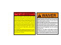
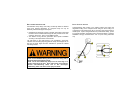
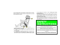
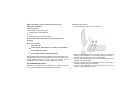
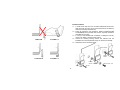
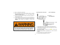
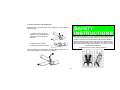
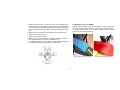
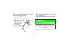
Installation- and Operating Instructions for Racing Harnesses For FE-Models see supplemental Instruction EA 8.2.1 CONTENT WARNINGS AND SEVERALS 1 WAIVER and General Information Rules and Regulations HOMOLOGATIONS Definitions Homologations The asm® Safety System Racing Harness Models ANCHORAGE LOCATIONS AND GEOMETRIES - 3 RESTRAINT INSTALLATION 33 - 56 - 2 3 Initial Harness Adjustment during Installation Wrap systems and Installations 34 33 - 40 4 - 16 5 7 9 4 - 7 - 8 - 16 17 - 28 Belt routing 17 What happens during a frontal impact? 18 - 20 Lap-, Shoulder- and Anti-sub strap routing 21 - 24 24 - 28 Specifics for 5-Point, 6-Point, Formula and HYBRID Models IMPORTANT INFORMATION ABOUT BOLTS AND TORQUES 29 - 32 Bolts and Torques Creating a new Attachment Point About Seats 29 30 - 30 - 31 32 “Flexi Belt™” 41 Double bar [Lap Belt] 42 Bracket and End Loop Installations 43 - 56 OPERATION 57 - 64 Wearing your Racing Harness safe How to release your Racing Harness 57 - 63 64 CARE AND MAINTENANCE 65 - 67 Examples of Wrong Installations ACCESSORIES AND SPARE PARTS / PATENTS / COPYRIGHTS - 67 68 - 70 T H I S M AN U AL C O N T AI N S I M P O R T AN T I N F O R M AT I O N THIS MANUAL CONTAINS IMPORTANT INFORMATION SHOWN AS S H O W N AS WARNINGS deal with important issues about installation, use, misuse or modification of the SCHROTH racing harness. SAFETY INSTRUCTIONS contain important hints to help you to install, use and maintain the SCROTH Racing Harness properly and effectively Ignoring these Warnings will significantly reduce the performance of the racing harness system. This can result in serious personal injury or death during an accident. Always read carefully and follow the information in this manual, especially those highlighted as above. -1- ABOUT THE IMPORTANCE OF THIS MANUAL ! SCHROTH has attempted to make this racing harness manual extensive and comprehensive. We have created it to help the reader understand racing harness installation, use and maintenance, and how it relates to safety in motorsports. Intensive research and experience in motorsports has led us to prepare up-to-date instructions for optimized anchor point locations and racing harness design features. The SCHROTH development of new racing harness configurations should be considered when defining anchorage locations. What was considered acceptable in the early and mid-1990s has changed and evolved as the result of currently available data. Therefore, we ask the drivers, mechanics, teams and race car manufacturers to read and heed the information in this manual carefully. Safe and effective HANS® use also depends on HANS® specific restraint routing and anchor point locations. This harness belt, when properly installed and used according to applicable instructions can minimise injury. The ability of any restraint system to minimise or prevent injuries is directly related to the type and severity of accident. No restraint system can prevent injury or death in every accident. PROFI and HYBRID racing harness belts are NOT designed to be installed into street legal vehicles, and DO NOT meet federal and state vehicle safety regulations. They are designed and tested to be used exclusively in race cars and only in on-track events. Only PROFI-FE asm® models are intent for Rally sport and street legal use and carry either the ECE-R 16 approval label for Europe or sets forth the following language for the USA: “meets the applicable provisions of FMVSS 209”. It will also carry the FIA homologation label. “This article is sold without warranty, express or implied, including but not limited to the implied warranties of merchantability and fitness for a particular purpose, all of which are specifically disclaimed, and no warranty or representation is made as to this product’s capability to protect the user from any injury or death. Racing is dangerous! The user assumes the risk “The sanctioning body regulating the motorsport series in which you are participating may have additional information specific to your chassis. All information in this document is based upon the best knowledge as of June 2004.” -2- R ULES AND Always heed all WARNING and SAFETY INSTRUCTION boxes. Always read and heed all instructions in this manual carefully. Failure to follow WARNING, SAFETY INSTRUCTIONS and all other instructions could result in severe personal injuries and death. R EGUL ATION S This manual contains important information about installation and use of your new harness belt. Read this manual thoroughly and understand the content before attempting installation. Knowledge gained from extensive testing and accident analysis has increased significantly over the past years so it is important to read and follow the instructions given in this manual, even if you have installed harness belts previously. These instructions represent state-of-the-art knowledge at the time of issuance of this manual, the date of which is set forth on its cover. All instructions are in accordance with current FIA, NASCAR, CART, SCCA and other sanctioning body regulations, as individually indicated in the text. Deviating from these instructions may result in rejection from participation in motorsport events. Regulations may change with short notice and may not be incorporated into these instructions at the date of purchase. Keep yourself up-dated about the latest regulations for the motorsport in which you are participating. Latest information can also be obtained from the SCHROTH website www.schroth.com I N T E ND E D U SE , D E FI NI TI O NS AND L ABE LL I NG PROFI and HYBRID racing harnesses, except for PROFI-FE models, and are not approved or intended for use on public roads or off-road. They are designed and approved only for closed circuit race tracks. For legal street use, SCHROTH offers special United States Department of Transportation approved models (FE-models). NEVER use unapproved PROFI and HYBRID racing harnesses on public roads or off-road. The SCHROTH Profi-, Profi-FE and HYBRID models are harness belt systems designed, tested and homologated for adult-sized persons, regardless of age. Webbing stretches during an accident to convert energy and to keep body loads within an acceptable range during survivable crashes. Persons not meeting the minimum weight and body size, as set forth below, may not benefit from this design feature. Severe personal injuries or death may occur. D O Y O U H AV E E X PE RI E N CE I NST ALLI NG R ACI NG H AR N E S SE S ? The installation procedures explained in this manual assume that you have the knowledge, experience and tools required to install racing harnesses. If you do not have the knowledge, experience and/or tools required or do not understand the instructions, do not install the harness belt – have the harness belt system installed by a professional who will be able to do the job correctly. Your safety and the safety of others who will use the harness belt system are at stake! -3- Definitions Persons who weigh less than 40 kg [88 lbs.] or who are less than 150 cm [4‘11“] tall, regardless of age, must NEVER use SCHROTH racing harnesses. Approvals for racing harnesses are granted by sanctioning bodies like FIA, NASCAR and SFI. Some SCHROTH racing harness models are approved by multiple sanctioning bodies and therefore may carry multiple labels. One of these labels should apply to the motorsport in which you are participating. -4- FIA homologated racing harnesses Identification labels, which bear the homologation number and the expiration date may be attached to each individual subassembly of the racing harness not permanently fixed to the buckle. Valid FIA labels may show various homologation numbers depending on the installation of an anti-sub strap [sub = abbreviation of submarining = sliding underneath the lap belt during a frontal impact]. E.g.: (B) = no anti-sub strap [4-point harness] (C) = with anti-sub strap I [5-point] (D) = with anti-sub strap II, F-models and HYBRID [6-point] Racing harnesses manufactured for motorsport in countries, or for racing series that fall under the FIA regulation, must carry the appropriate FIA labels. FIA-labelled belts are valid for five [5] years from last day of the year of manufacture unless regulated differently by the sanctioning body of the motorsport in which you are participating. The last year of FIA validity is indicated on the label. Each separate strap assembly is labelled. not valid after SAFETY PRODUCTS not valid after 2008 2008 FIA B-137.T/98 FIA C-129.T/98 FIA D-130.T/98 FIA C-129.T/98 FIA D-130.T/98 Made in Germany Made in Germany example of a FIA identification label example of a FIA homologation label For homologation number per each model see pages 8ff. -5- NASCAR Approved Racing Harnesses FIA and other sanctioning bodies allow 50 mm (2”) wide HANS specific shoulder straps to be worn only when used with a HANS®. Such shoulder belts are labelled. Racing harnesses approved for use under NASCAR regulations carry the Month/Year of manufacture. They are valid for two years from that date of manufacture. Such models may also carry a FIA label. Note that the extended lifetime of the FIA label DOES NOT APPLY to NASCAR use. The approval for use in the NASCAR series is published in NASCAR bulletins, but such approval is NOT labelled on the restraint. SAFETY PRODUCTS not valid after 2008 SAFETY PRODUCTS not valid after for HANS use only 2008 FIA D-136.T/98 Date of Mfg: July 2006 Made in Germany FIA D-130.T/98 SSP PIN: 46015 Profi III-6H Made in Germany -6- SFI Approved Racing Harnesses Models with SCHROTH asm® Safety System Racing harnesses specifically manufactured for motorsport requiring SFI 16.1 approval are SFI tested and labelled. These racing harnesses MUST be replaced two years after the month and year of manufacture. The date of manufacture is indicated on all three SFI labels – [1] at the lap belt, [2] at the shoulder harness and [3] at the Anti-Sub Strap. The asm® System asm® is the acronym for anti-submarining [submarining = sliding underneath the lap belt during a frontal impact]. This phenomenon is likely to occur in a 4-point harness belt, and is significantly reduced by the patented asm® safety system. Therefore, all SCHROTH racing harnesses sold as 4-point harnesses, and likely to be used as such, are equipped with the asm® system. It consists of an energy converter located in the inboard shoulder belt. As a result, make sure you have purchased left and/or right harnesses, depending upon which side you want to install the harness. Since every accident is different, always keep in mind that PROFI-asm® harness belts, just like other racing harnesses, cannot guarantee against severe injuries, death and other risks during an accident. Recently developed head and neck supports or restraints, however, allow further reduction of head deceleration and neck forces. The SCHROTH asm® safety system cannot substitute for the effectiveness of e.g. a HANS®. The asm® system should never be used with such devices since it provides for a slight rotation of the upper body as well as some shoulder belt slack which are not wanted in conjunction with any head and neck restraints. -7- Profi II-asm® ® • Never wear a harness restraint without asm system as a 4point harness. Submarining may take place during an accident and severe injuries or death may occur. ® • The shoulder belt assembly containing the asm safety system must be on the inboard shoulder strap when the system is installed. Never install on the wrong side of the vehicle. The system will not function properly in an accident and serious injuries or death may occur. ® • Never use a harness belt with asm system in conjunction with any head and neck restraint. The effectiveness of such devices may be impaired by the elongation from the energy converter in ® the asm system. • • • • Lap belt: II stands for 50mm [2”] in width. Flexi-belt™ assembly to allow pull-up and pull-down installation Shoulder belt: 75mm [3"] in width. The asm® safety system reduces the risk of submarining when being used as a 4-point harness. • Never use this asm® system with any head and neck restraint. See WARNING above. Can be up-graded to 5-point or 6-point racing harnesses by choice. [See Anti-sub Strap I and II description.] Homologations: FIA labelled as 4-point, 5-point and 6-point version so any configuration can be used. Approval: FIA B-137.T/98 Models Sfi 16.1 or Sfi 16.5/NASCAR approved racing harness may vary from the drawings shown. However, the changes in brackets or adjusters and adjuster positions from the use of approved racing harnesses, and the varying methods of installation and operation that result, can easily be followed since each racing harness component and its use is described in the appropriate sections of this manual. [See, e.g. the “Brackets” section, explaining the correct installation and operation also of Sfi 16.1 or Sfi 16.5/NASCAR approved racing harnesses.] -8- Anti-sub Strap models I and II I Profi III-5 II I stands for single strap to up-grade PROFI II asm® into 5-point restraint. II stands for dual strap with T-bar to up-grade PROFI II asm® into 6-point restraints Each anti-sub strap model is FIA labelled matching the appropriate homologation numbers on PROFI II asm®. • • • -9- Lap belt: 75 mm [3”] in width Shoulder belt: 75 mm [3"] in width Approvals: FIA C-129.T/98, SFI Profi III-5H • • • Profi II-6 Lap belt: 75 mm [3”] in width, Shoulder belt: 75 mm [3”] lower portion, converting into 50 mm [2”] HANS specific upper shoulder belt section. Approval: FIA C-129.T/98, SFI • • • • • - 10 - T-bar type 6-point racing harness Lap belt: 50 mm [2"] in width, “Flexi Belt™” assembly to allow pull-up and pull-down installation Shoulder belt: 75 mm [3”] in width Approval: FIA D-130.T/98 Profi II-6H • • • • • Profi III-6 T-bar type 6-point racing harness Lap belt: 50 mm [2”] in width, “Flexi Belt™” assembly to allow pull-up and pull-down installation Shoulder belt: 75 mm [3”] lower portion, converting into 50 mm [2”] HANS specific upper shoulder belt section. Approval: FIA D-130.T/98 • • • • • - 11 - T-bar type 6-point racing harness Lap belt: 75 mm [3”] in width, Shoulder belt: 75 mm [3”] in width Approvals: FIA D-130.T/98, SFI for NASCAR approvals see bulletins or Sfi 16.5 labelling Profi III-6H Profi II-6F • • • • • • • • • • T-bar type 6-point racing harness Lap belt: 75 mm [3"] in width, Shoulder belt: 75 mm [3”] lower portion, converting into 50 mm [2”] HANS specific upper shoulder belt section. Approval: FIA D-130.T/98, SFI for NASCAR approvals see bulletins or Sfi 16.5 labelling - 12 - Formula-type [D-ring] 6-point racing harness Lap belt: 50 mm [2"] in width, Shoulder belt: 75 mm [3”] in width Approval: FIA D-136.T/98 Intended for made to measure bucket seats in single seaters and open wheelers Profi II-6FH Profi III-6F Profi II-6FHD • • • • • Formula-type [D-ring] 6-point racing harness Lap belt: 50 mm [2"] in width, Shoulder belt: 75 mm [3”] lower portion, converting into 50 mm [2”] HANS specific upper shoulder belt section. Approval: FIA D-136.T/98 Intended for made to measure bucket seats in single seaters and open wheelers • • • • • - 13 - Formula-type [D-ring] 6-point racing harness Lap belt: 75 mm [3"] in width, Shoulder belt: 75 mm [3”] in width Approval: FIA D-136.T/98, SFI, for NASCAR approvals see bulletins or Sfi 16.5 labelling Intended for made to measure bucket seats in single seaters and open wheelers Profi III-6FH HYBRID II Profi III-6FHD • • • • • • Formula-type [D-ring] 6-point racing harness Lap belt: 75mm [3"] in width, Shoulder belt: 75 mm [3”] lower portion, converting into 50 mm [2”] HANS specific upper shoulder belt section. Approval: FIA D-136.T/98, SFI for NASCAR approvals see bulletins or Sfi 16.5 labelling Intended for made to measure bucket seats in single seaters and open wheelers • • • • - 14 - SCHROTH patented unique 6-point racing harness Lap belt: 50 mm [2"] in width, Shoulder belt: 75 mm [3”] in width, Approval: FIA D-180.T/98 HYBRID II-H HYBRID III HYBRID II-HD • • • • SCHROTH patented unique 6-point racing harness Lap belt: 50 mm [2"] in width, Shoulder belt: 75 mm [3”] lower portion, converting into 50 mm [2”] HANS specific upper shoulder belt section. Approval: FIA D-180.T/98 • • • • • - 15 - SCHROTH patented unique 6-point racing harness Lap belt: 75 mm [3"] in width, Shoulder belt: 75 mm [3”] in width, Approval: FIA D-180.T/98, SFI for NASCAR approvals see bulletins or Sfi 16.5 labelling HYBRID III-H HYBRID III-HD • • • • • SCHROTH patented unique 6-point racing harness Lap belt: 75 mm [3"] in width, Shoulder belt: 75 mm [3”] lower portion, converting into 50 mm [2”] HANS specific upper shoulder belt section. Approval: FIA D-180.T/98 for NASCAR approvals see bulletins or Sfi 16.5 labelling - 16 - A NCHORAGE L OCATIONS AND G EOMETRIES Therefore, it is essential that strap routing be optimised as described in the following graphs. B EL T R OU TIN G The expected restraining function of any seat belt or racing harness can only be achieved by • optimised strap routing around and from the wearer’s body • optimised anchor point locations An occupant can be effectively restrained ONLY by load transfer through the hard points of the occupant’s body. The only accessible hard points are the following: • pelvic • thorax [chest] ] to a limited level only • clavicle [shoulders] - 17 - W H AT H AP PE NS DURING A FRON T AL IMPAC T : W H AT DOES THE DISCUSSION OF FRONTAL IMP AC TS ME AN TO THE OCCUP AN T ?: This data is based on an optimised installation with an upright seating position during dynamic testing. It simulates a 90° head on collision, utilising a 75 kg [165 lb] mass dummy, an impact velocity of 50 kph [31 mph] and a stopping distance of approximately 400 mm [16”] with a maximum deceleration of 30 g [FIA 8854/98 dynamic test requirements]: ¾ The pelvic load, expected to surpass 14 kN [3,100 lb] at each side, will elongate the lap belt and compress the tissue on the pelvis. The pelvis will slide forward by 80 to 100 mm [3”-4”] ¾ The upper torso load is expected to surpass 7 kN [1,550 lb] on each strap, will elongate the shoulder belts, the upper body will roll in, the adjusters will move up the chest by approximately 200 mm [8”] and forward head trajectory will be up to 400 mm [16”] ¾ The pelvic movement combined with the shoulder belt forces will load the anti-sub straps to more than 6 kN [1,320 lb] each in a 5or 6-point racing harness and can be intentionally higher in a F-type model where the anti-sub straps are routed rearwards. In more reclined seating positions, the pelvic load will be reduced to approx. 9 kN [2,000 lb] since the seat pan, designed as a ramp, will take some of the load. Therefore it is essential the seat or chassis manufacturer ensure the seat pan is strong enough not to bend or even collapse under extreme loads. The numbers above seem to be quite high when compared with actual racing accidents. Fortunately, most racing accidents are not 90° head-on collisions. Car deformation is greater than the 400 mm [16”], and modern soft walls also convert impact energy. Therefore, accidents with higher impact speeds are often less severe than the FIA required test set up. However, SCHROTH racing harnesses have been tested to speeds and decelerations surpassing FIA requirements. - 18 - T HIS WILL HAPPEN TO YOUR BODY AND RACING HARNESS : WI THOUT HANS ® SYSTEM WI TH ¾ The forward pelvic movement will lower belt angularity, which can result in submarining. If the initial angle is not with the suggested range, submarining may result in severe internal injuries or death as the belt rides into the soft tissue above the pelvic bone behind which are the liver and kidneys. ¾ The lap belt will slide into the corner of the bucket seat openings, and incorrectly positioned adjusters will interfere with the seat. This may cause the adjuster to loosen the lap belt or cut the webbing, thereby significantly diminishing effective restraint and resulting in serious injury or death. ¾ Lap belts perform best when their anchor points are located adjacent to the seat width. Routing outward will increase the strap load resulting in further elongation. The resultant stress may exceed the structural strength of the racing harness or the anchor points. [E.g. a 45° routing off the body will increase the load by approximately 40% compared to the ideal routing]. The racing harness could therefore come apart, eliminating restraint and resulting in severe injury or death. ¾ A shoulder belt adjuster positioned too high will ride further up and may cut into the occupant’s neck, which could result in severe injury or death. Its rigidity also increases the likeliness of clavicle [shoulder] fractures. ¾ With the expected strap elongation and body compression it is impossible to avoid head impact onto the steering wheel. Extreme head deceleration loads, spine stress and neck tension may occur to cause basal scull and spinal fractures and resultant severe injury or death. HANS ® SYSTEM ¾ The most effective way to reduce the risk of head and neck injuries is by wearing a HANS®. ¾ Extremely long shoulder belts allow for extra elongation and head movement and must be avoided. ¾ Long shoulder belts also provide more slack during the rebound phase so the belts may slide off the occupant’s shoulders or, even worse, off a HANS® if worn. SCHROTH HANS® specific restraints come with lower elongation rates designed for such strap lengths. ¾ Inappropriate installation of the lap and shoulder belts can increase load to the anti-sub straps resulting in groin injuries or anti-sub strap failures resulting in severe injury or death. ¾ Inappropriate anti-sub strap installation can also result in the harness failing to restrain the occupant, with resulting severe injury or death. - 19 - S LED T ESTING WITHOUT S LED T ESTING WITH HANS ® HANS ® - 20 - ¾ Lap belt downward angle should be approximately 60° measured from the horizontal, passing through the occupant’s hip joint. This is the suggested angle for upright seating [15-20° backrest declination]. A higher backrest declination, e.g. 30° – 40°, as is common in open wheel race cars, requires a belt angle of 70° – 80°. ¾ Make sure there are no sharp edges [seat structure, seat mounts, chassis] that may tear or cut the lap belt webbing. Optimal performance of your racing harness requires proper installation and proper use. Heed and obey the following instructions with respect to racing harness geometry and routing. S HOULDER B EL T R OU TING ¾ Shoulder belts must run from the shoulders horizontally or down, at no more than a 20° angle. ¾ In cases where the shoulder belts must be routed down to the chassis floor, support by a roll cage bar or harness guide at the appropriate height is essential to establish the horizontal shoulder strap routing off the shoulder/HANS®. Most racing seats are not designed and tested to carry shoulder belt crash loads from downward installation. Severe injury or death could result. A 45° downward shoulder belt installation is possible with seats that SCHROTH has positively tested to take a load measured during a 50 kph [31 mph] and 28 G impact. Refer to the list of SCHROTH approved racing seats in section “Bolts, Seats and Stuff”. WARNING: 45° downward shoulder belt installation must never be used with HANS®. ¾ For the best restraint of the occupant’s upper torso, anchor points should not be further back than 200 mm [8”] from back of user’s seat. ¾ In the event that the anchor points are further towards the rear of the vehicle [e.g. using a roll cage bar for wrap around attachment] the distance between the strap anchorages will narrow or even cross over as described in following graphs and formulas. ¾ It is especially crucial to follow this strap routing when HANS® is in use. • Bracket installation and operation. • Wearing the racing harness. • Adjusting the racing harness. L AP B EL T R OU TING To achieve optimal restraining function – lap belt strap length must be as short as possible. This requirement can be achieved by following the instructions set forth below: ¾ Distance between the lap belt anchor points should not be greater than the width of occupant’s pelvis or the outer width of the occupant’s bucket seat. The distance of approximately 400 mm [16”] is recommended. If there are choices of several anchor points choose those that come the closest to these recommendations. ¾ Lap belt straps must be routed over the pelvic bone to stay firmly and tightly in the crest between the pelvic bone and the upper thigh. - 21 - - 22 - Formula: Y = Z - [X * 0,50] For wrap around installation, 75 mm [3”] webbing Reduce results if a HANS® specific harness is to be installed by 25 mm [1”] Shoulder belt mountings located more than 8 inches from the back of the user’s seat or angled upwards ar not good restraint practice and are most strongly discouraged. If longer belts are used, the inside edges of the belts should be still closer together at their mounting points, even touching or crossing, but both belt and HANS® performance are severely compromised. P OSITIONING OF Z = [mm] 250 X [mm] Y [mm] 200 150 Z = [inch] 10 X [inch] Y [inch] S HOULDER S TRAP A NCHOR P OINTS 8 6 300 100 400 50 500 0 600 -50 700 -100 800 -150 12 4 16 3 20 3 24 -3 28 -4 32 -5 side by side side by side crossed over For bolt on installation, 7 5 m m [ 3 ” ] we b b i n g X = Distance from Shoulder Points to attachment. Take the measurement from the highest shoulder point [on top of the HANS® collar if warn] Z = Distance from the middle of the left shoulder point of the webbing to the middle of the right shoulder point of the webbing. Y = Approximate distance between anchor points. [measured from the middle of the webbing at the left anchor point to the middle of the webbing at the right anchor point] Reduce results if a HANS® specific harness is to be installed by 25 mm [1”] Z = (mm) 250 X (mm) Y (mm) 200 150 Z = [inch] 10 X (inch) Y (inch) Approximate result: the shoulder belts will cross over when the anchor points are located more than approx. 500 mm [20”] behind the seat backrest. - 23 - 8 6 300 100 400 50 500 0 600 -50 700 -100 800 -150 12 4 16 2 20 2 24 -2 28 -4 32 -6 side by side side by side crossed over A NTI - SUB P ROFI 5- POIN T STR AP ROUTING Anti-submarine strap design and routing are directly related to effective upper torso restraint. Remember, an occupant’s body can only be effectively restrained through its hard points. MODELS Anti-submarining strap routing in any seating position must follow the tangential touching of the occupant’s chest and groin. Such routing is a compromise to help reducing the risk of crotch and groin injuries during a frontal impact. 5-point racing harnesses are provide lesser safety, proven by computer simulation, sled testing and in real word accidents,. Therefore SCHROTH strongly recommends the use of 6-point racing harnesses only. ¾ SCHROTH has developed a range of models, which allow a direct load transfer from the shoulder belts through the rotary buckle into the antisub strap. See Profi 5-, Profi 6- and HYBRID models. ¾ The different racing harness geometries allow specific installation according to the requirements of each model. The soft tissue on the upper thighs is not considered a hard point. Therefore the Formula-type [D-ring] anti-sub straps are designed to run flat over the upper thighs and then rearwards to provide the needed restraining function. Never use the SCHROTH Racing Harness unless the racing seat is designed with anti-submarining holes. Never run the anti-submarining straps over the front edge of a factory seat down to the floor. Such routing does not provide the desired anti-submarining effect, and in fact encourages submarining, which can cause severe injury and death. - 24 - P ROFI 6- POIN T AN D HYBRID P ROFI F- MODELS MODELS • Anti-submarining strap routing shall be vertical down from the groin, preferably approximately 20° back. • Anchor points shall be approximately 100 mm [4”] lateral apart from each other. In case of a a low seating position (e.g. in open wheel race cars), this separation may be reduced since the anchor points are closer to the thighs. The anti-submarining strap routing over the upper thighs and attachment to the shoulder belt latches with the buckle in between, does not provide a direct load path from the shoulder belts down to the anti-submarining strap anchor points. The indirect routing requires a type of preloading of the anti-submarining straps during a frontal impact. This is achieved by sitting on the anti-submarining straps, routing them rearwards and attaching them in the region near or on the lap belt anchorages. This anti-sub strap design requires sitting on the straps or having a thin seat panel allowing the straps running rearwards right underneath the driver’s buttock. - 25 - In single seaters HANS® specific double-shoulder belts require 2 anchor points for each shoulder: One for the 75 mm [3”] “body belt” and one for the 50 mm [2”] “HANSbelt”. For correct height and lateral routing see sketches below. The “HANS-belt” attachment must follow the “Positioning of Shoulder Strap Anchor Points” instructions described earlier. Anti-sub straps must not be redirected. Redirected straps, e.g. using an OE stock seat for a formula type racing harness and running the straps over the seat edges down to an anchor point, will provide extra slack during a crash and the expected performance will not result. Slack from such anti-sub strap routing will allow a buckle ride up during an accident which results in higher upper torso and head movement. This increases the risk of head impact, head and neck injuries and internal injury. MONOCOQUE INSTALLATION: - 26 - All wrap around installation: INSTALLATION IN A SEDAN WITH ROLL CAGE: HANS® size R (European Model size M) „HANS-belt“ X „HANS-belt“ Y Z = (mm) 225 X (mm) Y (mm) HANS-Gurt Y (mm) Körpergurt 200 145 230 Z = (inch) 9 X (inch) Y (inch) HANS-belt Y (inch) Body-belt 8 6 9 300 105 230 400 65 190 500 50 175 600 -50 175 700 -50 175 800 -70 195 12 4 9 16 2,5 7,5 20 2 7 24 -2 7 28 -2 7 32 -3 8 HANS® size L Z Installing the belts to a rear roll cage bar, the body-belt attachment must be positioned next to the “HANS-belt” attachment. The “body belt” attachment shall be closest to the “HANS-belt”. - 27 - Z = (mm) 250 X (mm) Y (mm) HANS-Gurt Y (mm) Körpergurt 200 300 400 500 600 700 800 170 130 90 50 50 -50 -70 250 250 205 175 175 175 195 Z = (inch) 10 X (inch) Y (inch) HANS-belt Y (inch) Body-belt 8 7 10 12 5 10 16 4 9 20 2 7 24 2 7 28 -2 7 32 -3 8 In case of a wrap around installation to a roll bar make sure the transversal positioning of the shoulder straps is permanently secured by some means, e.g. FIA 8857-2001 like rollbar padding, hose clamps or similar devices. - 28 - IMPORT ANT INFORM ATION ABOUT BOLTS AND Bolts not supplied by SCHROTH must be of grade 8.8 at a minimum. TORQUES 1. Bolts must fit to the thread dimension of the anchorage chosen. Bolt Diameter 2. Bolts must be long enough to fill the thread hole completely with all bushings, spring washers, spacers etc. in place for installation. • Stock thread holes commonly are 7/16” 20 UNF. Therefore, all SCHROTH models come with bolts and eye-bolts matching this dimension. • A few chassis are manufactured with 15/32” or ½” thread holes at the inner [centre tunnel] anchorages. See the section “Brackets” for those thread holes that accept 15/32” or ½” bolts. • Individually made chassis and roll cages often use other dimensions, which vary from 8 mm or 5/16” [mostly for anti-submaring strap installation] to 10 mm or 3/8” in diameter for lap- and shoulder belt installation. • Eye-bolts for 10 mm thread holes [P/N SG35] are available at your SCHROTH-dealer or importer. • For all other dimensions you must provide the correct bolt diameter, type of thread and bolt length. 3. Bolts must be of correct length and must not to intrude into the fuel tank or damage any other components of the car in which they are installed. • Never use bolts of the wrong diameters or bolts that are too short and may allow the bolts to become loose and separate from the anchorages. Use of improper bolts will cause the racing harness to fail. • Never use bolts that are too long and may intrude into the fuel tank or other parts of the car. • Always tighten bolts with the proper torque. Improperly tightened bolts may loosen during harness belt use and may become separated during a crash. • Never over-tighten bolts. Over-tightening bolts may destroy the thread and allow the bolt to separate during a crash. BOLT FAILURE MAY RESULT IN SEVERE INJURIES OR DEATH. - 29 - CREATING A NEW ATTACHMENT POINT • Follow the recommendations for geometry and strap routing described on Pages 23 to 25 to define the proper anchor point location. • FIA does not allow welding or drilling to roll cages, except those conducted and certified by the roll cage manufacturer. Only manufacturer specified roll cage bars must be used for racing harness installation thereto. • For new attachment points to the chassis heed the following WARNING box. Never try to drill a larger bolt hole into any harness belt bracket. The bracket may stick to your drill bit and the bracket and attached webbing and its hardware may spin and may heavily injure or even kill you. TIGHTENING TORQUES BY BOLT DIMENSION • Each bolt diameter and type of thread requires an individual torque for proper tightening. These torques as listed below are defined by national or international standardisation organisations. • For safe installation always tighten bolts to the recommended torque. • For any installation use e.g. “Loctite 243” or spring washers where recommended to secure bolt fastening. M8 Torque in Nm Torque in lbinch 25 18,5 5/16” M 10 3/8” 25 18,5 50 37 50 37 7/16” 15/32” 20 UNF 40 30 87 64,5 If you intend to drill a hole, make sure not to damage the fuel tank, fuel lines, electrical wires, brake lines or other important components. Any damage to such components can result in fire or explosion and severe injuries or death can result. • For new attachment points to the chassis you must use a FIA specified reinforcement plate [see list of accessories on Page 62]. • Drill a hole of 12 mm [15/32”] diameter for lap- & shoulder belt and 5point anti-sub strap attachments. • Drill a hole of 8,5 mm [5/16”] diameter for anti-sub strap twin bracket 1/2” 113 83,5 - 30 - reinforcement plate. • Use seal compound and stick the reinforcement plate from underneath to the floor panel. The seal also helps to prevent water intrusion. • Use SCHROTH supplied bolts and eyebolts only! They are tested for quality and fit to the threads provided by the SCHROTH reinforcement plate and to the SCHROTH brackets. In case your car is raised/pumped up on a lifting platform or sits on chocks make sure it is safely secured against accidental or unintentional drop and against external unwished down operation before you position yourself underneath the car. - 31 - A B O U T S E AT S SCHROTH approved special seats: S E AT R E Q UI REM E NTS Seats approved by SCHROTH installation more than 20° down. for shoulder belt FIA homologated Seats: Keiper Recaro: 070.80.xxx Profischale, 070.81.xxx Profischale 070.90.032 Profischale SP-A, 070.91.032 Profischale SP-G Pole Position König: RS 1000 , RS 2000, RSL 1000, RSL 2000 No racing harness will function properly when installed in vehicles equipped with seats having no headrest or having backrests with integrated headrest and no openings between the backrest and the headrest [e.g. stock Porsche seats]. In such seats the shoulder belts will slide off occupant’s shoulders during an accident. Never modify factory seats to create new slots. The seat structure may be impaired or sharp edges of the seat frame may damage the racing harness webbing. Severe injuries or death may occur. Protech Seating Limited (Corbeau): PRO-RACE PR-1 SEAT, PRO-RACE PR-3 SEAT, PRO-RACE PR-4 SEAT, PRO-SPORT PS-1 SEAT, PRO-SPORT PS-3 SEAT, PRO-SPORT PS-4 SEAT Wiechers: 300, 301, 302, 303, 304, 305, 307, 403/413, 404/414 SCHROTH made by König: RS 1000, RS 2000, RSL 1000, RSL 2000 For actual list visit www.schroth.com/seatlist - 32 - INITIAL RESTR AINT ADJUSTMENT DURING For more details see instructions in section “Wearing your Racing Harness correctly” • Lap belt tilt lock adjusters must not be positioned within the openings of the bucket seats. Adjusters must be either outside of the seat at a minimum distance of 40 mm (1.5”) from the opening or close to the rotary buckle insides the seat. • Anti-sub strap tilt lock adjusters are recommended to be positioned either in the opening of the seat pan or right above. This position will allow adjustment without interfering in an uncomfortable manner with your upper thighs. INSTALL ATION While first installing your racing harness the following items may require minor adjustments to the belts. Roll cage bars used to mount the shoulder belts must be homologated by the roll cage manufacturer for such use. Each shoulder and lap belt anchor point must withstand a minimum load of 14,7 kN (3.240 lbs). Each anti-submarining anchor point must withstand a minimum load of 7,2 kN (1.650 lbs). Any drilled hole for racing harness attachment must be strengthened by a reinforcement plate meeting FIA specification (see list of accessories on Page 62) SCHROTH recommends, whenever possible and suitable, the use of existing factory provided anchor points for the lap- and shoulder belts. • Shoulder belt tilt lock adjusters must be positioned 250 mm (10”) below the collar bone or even lower. • If a HANS® is worn, the adjuster must be positioned low on the yoke end of the HANS®. • For a HANS specific double-shoulder belt system, the adjuster has to be positioned so the merge between the “HANS-belt” and the “bodybelt” must be located at a certain distance below the HANS® yoke tips. - 33 - I N S T AL L ATI O N W RAP S YSTEMS TO ROLL B AR INST ALL ATION AN D BR ACKETS ASSEMBLY 3- B AR STEPS: 1. slide the webbing through slot 1 and 2 as shown S LI DE WR AP This installation is commonly used for • shoulder strap roll cage installation and • to assemble open strap ends to brackets. Do not install a lap belt directly to a roll cage by wrap around technique. W H AT DO YO U NE E D : open strap ends a 3–bar slide for either 50mm (2“) or 75mm (3“) wide webbing and an accessible roll cage bar or an homologated bracket made by SCHROTH. 2. make sure the protruding strap end is long enough to have sufficient webbing length available for the following wrapping procedure. A minimum of 360 – 400 mm (14” – 16”) is recommended. 3. the 3-bar slide shall be positioned as close as possible to either the roll cage bar or to the end bracket. 4. wrap the free strap end from underneath around the roll cage bar or through the webbing slot of an end bracket. 5. in case of the combination of a 50 mm bracket slot and 75 mm webbing, fold the webbing in as shown. Racing harness with end brackets assembled to the shoulder belts by a 3bar slide allow to dismount the brackets and use the 3-bar slide for wrap around installation directly to the roll cage. Also brackets can be exchanged e.g. from a snap-on to a bolt-in bracket or vice versa. Sfi 16.5/NASCAR Regulations: Brackets with at least 50 mm (2”) wide slots are required for use with 75 mm (3”) wide webbing. Snap-on brackets are not allowed. - 34 - 6. wrap webbing back through slot 2 and 1. 7. fold strap end back and run it through slot 2 again. 8. make sure the strap end protrudes at least 100 mm (4“) or even longer from slot 2. If it is less than 100 mm disassemble and start over again. If longer, roll in the strap end and fix it by a cable tie to the shoulder belt. 9. Check again for proper shoulder belt tilt lock adjuster positioning and for the 3-bar slide to be as close as possible to the roll cage bar or end bracket. - 35 - L IGHT W EIGHT D-R ING [50 MM (2”) AND 75 MM W R AP P I N G IN S TR U C TI O N S : (3”)] W RAP This installation is to be used for • shoulder strap installation to o roll cages o elbow brackets in open wheel race cars o SCHROTH HANS® adaptor for open wheel race cars • as 50 mm [2”] version also to assemble open strap ends to brackets. Do not install a lap belt directly to a roll cage by wrap around technique. W H AT DO YO U NE E D : 1. position D-Ring slide to roll bar with wider bar atop open strap ends the D-Ring type slide for either 50 mm (2“) or 75 mm (3“) wide webbing an accessible roll cage bar 2. slide a minimum of 600mm (24”) of strap length through D-Ring slide and from underneath around roll bar [first loop] or an homologated bracket made by SCHROTH. 3. slide strap from atop through D-Ring slot towards roll bar and back between roll bar and first loop until it protrudes from slot in D-Ring slide. 4. Pull at shoulder belt to check that wrap will tighten when being loaded. Racing harnesses with an end bracket assembled to the shoulder belt by a D-Ring slide, allow to dismount the bracket and use the D-Ring slide for wrap around installation directly to the roll cage bar. The diameter of that bar shall not exceed 50 mm [2”]. This D-Ring slide system is not to be used to attach 75 mm [3”] webbing to brackets with less than webbing wide slots. 5. Wrap strap end around roll bar again [third loop] and thread through DRing slide again. Shoulder belt is now sandwiched between first loop webbing and protruding strap end. 6. Make sure strap end protrudes at least 100 mm [4”] - 36 - Webbing should be crossed if the distance from the seat openings to the mounting bolt point or harness bar exceeds 450 mm (18”). When mounting to a harness bar with a wrap mount and the distance to the bar from the seat is less than 450 mm (18”), a section of roll bar padding, fixed with cable ties, should be added to the outside of each of the shoulder harnesses to ensure that they can not further separate when unloaded. 3-Bar Adjuster pictured in the examples is not positioned next to the bar and the final locking portion of the wrap has not been completed. This will result in significant slippage through the adjuster and significantly more elongation of the shoulder belts. Wrong wrapping or 3-bar slides too far away from the roll cage bar or from any bracket may allow webbing to slide during an accident. Extra elongation will occur which may reduce the effectiveness of the racing harness and the HANS®, if worn. Shoulder belts may slide off the HANS® or will give extra way allowing head and chest impact onto the steering wheel. Severe injuries or death may occur. WRON G I CORR ECT I N S T A L L A T I O N N S T A L L A T I O N example for a spreader using FIA 8857-2001 padding material - 37 - B O L T - I N W R AP B R A C K E T ASSEMBLING 3. fold back up from the body side through slot 1 and back down through slot 2 • Racing harness with 50 mm (2”) or 75 mm (3”) webbing and open strap ends • a bolt-in wrap bracket with 50 mm (2”) webbing slot [B 63] 4. fold back through slot 3 and finally through slot 1 or • a bolt–in wrap bracket with 75 mm (3”) webbing slot [B 45] Installation procedure 1. webbing shall wrap from the body facing side of bracket up into slot 1 5. pull at belt to check that wrap will further tighten. 2. pull through approx. 270 mm (11”) through and fold down through slot 3 temporarily leaving 50 mm (2”) of slack. - 38 - L i gh t W e igh t W ra p Sys t e m [ LV 4] This light weight system assembles directly to 50 mm (2”) slot brackets and is therefore commonly used by SCHROTH for anti-sub strap bracket and for the “Flexi-Belt™” assembly of both, the buckle latch and the bracket. This system is also absolutely micro slip free. For the light weight wrap system you need: 6. make sure the protruding strap end is at least 50 mm (2”) long • Racing harness with 50 mm (2”) webbing and open strap ends • a bracket or latch with a 50 mm (2”) strap slot • a wrap hardware (Part No. LV 4) The webbing must be wrapped tightly! Wrapping instructions 1. Place LV 4 with its thicker bar onto the bracket/latch. 2. Run strap end through slot at LV 4 and then from underneath through webbing slot at bracket. Pull through at least 200 mm (8”) of webbing. Fold strap end over the wider bar of LV 4 and back through the gap between bracket bar and LV 4 bar. The protruding end must be sandwiched between the load taking strap end and an inner webbing fold through slot 1. If this is not achieved, check again for proper routing. - 39 - 3. Slide strap end further through the webbing slot at bracket/latch and then fold the strap end through the slot at LV 4. 7. In this case, the strap end now protrudes from the down side of the LV 4. 4. Pull at the load taking strap and the bracket to make sure, the webbing is properly clamped by the wrap hardware. The webbing must be wrapped tightly! 5. If this is not achieved, check for proper strap routing and follow these instructions step by step again. 6. If the protruding webbing is significant longer than the minimum of 50 mm [2”], you may fold it over again, run it through webbing slot of the bracket/latch and again back and through the webbing slot at LV 4. - 40 - F LEXI B ELT ™ ASSEMBLING VIA L IGHT W EIGHT W RAP S YSTEM • Follow the wrapping instructions above at both strap ends. • Make sure, when the latch is buckled in, the bent part of the buckle latch faces towards the body. See figure below. • Flexi Belt™ allows you to assemble the lap belt either as a pull up or a pull down version. • As end brackets you can assemble a snap-hook bracket or any other SCHROTH bracket with a 50 mm (2”) webbing slot. • For swivelling bolt-on installation, use the wrap bracket shown on page 38. The wrap hardware LV 4 is not to be used with this bracket. Follow assembly instructions for Bolt-in Wrap Bracket assembling. WRONG RIGHT • In a pull down configuration the adjuster shall be as close as possible located to the buckle • In a pull-up assembly make sure, the adjuster is well separated from the strap hole in the bucket seat so the adjuster will not interfere with the seat bucket during a crash. See section “Anchorage Locations and Geometries” - 41 - D OUBLE B AR L AP B ELT I NST ALL ATION This installation system is only used in some open wheel race cars. • Bars must not bend under strap load of at least 14.7 kN. • All edges must be appropriately rounded (>1,5 mm radius) • Make sure the system works with the SCHROTH designed thinner than common webbing. The bars must directly clamp on to each other without providing pre space for webbing. • Make sure the belt is correctly routed as recommended by FIA and shown in following sketch. Routing the lap belt not following these instructions may result in attachment failure during an accident. Webbing may either slide through the assembly or may be cut by the metal bars. Severe injuries or death may occur. - 42 - EYE BOLT INST ALL ATION FOR S N AP - O N A N D C A R A B I N E B R A C K E T S Eye-bolts for snap-on brackets may be installed either to • another anchor point provided by the car manufacturer or • anchor points provided by the roll cage manufacturer. • a newly created anchor point in conjunction with a proper reinforcement plate If you need a raised snap-on point, some of the SCHROTH stainless steel bolt-in brackets can be used as adapters. For further information see section “Bolt-in Brackets”. Installation Material and tooling needed: • • • • Eye-bolt Spring washer (1 or 2 ea) strong screw driver or metal bar or wrench for eye-bolt tightening in case of newly created anchor point: reinforcement plate Lock Nut Carabiner Definitions: • Assemble eye bolt and spring washer as shown in sketch beside. • Bolt in eye bolt and tighten securely. The optimum torque setting is 40 Nm (350 lbinch). Pull either screw driver or similar tool through eye and turn clockwise to tighten the bolt securely. • Make sure the eye’s ring is pointing in direction of pull as shown in drawing below. This position will reduce the risk of unintended loosening of the eye bolt by torque forces applied by the harness during racing. If you cannot achieve this position by further tightening or loosening the bolt by a maximum of ¼ turn, dismount the eyebolt and use 2 spring washers to come closer to the recommended position. Webbing Carabiner Lock Nut Counter Thread 1. The webbing must always be positioned on the smaller section of the triangular carabiner. The lock nut must always be positioned in the free section between the eye bolt and the webbing. 2. The lock nut always must fully catch the counter thread. No thread turn must remain free from the lock nut. - 43 - Bolt-in Brackets All brackets must be installed in direction of pull to avoid extensive stress to the anchor points during driving [fatigue stress] or during an accident.. Brackets for lap belt installation must either swivel [NASCAR requirement] or must be able to provide an alignment during a crash. Therefore SCHROTH provides bolt-in brackets only with sleeved bushings for swivelling or alternatively special designed stainless steel brackets which can be aligned with the direction of pull at the time of installation. - 44 - W R O N G W R O N G C O R R E C T C O R R E C T For 75 mm [3”] webbing either sewn in or assembled bracket B 23 C is available. Assembly is commonly done by using a 3-bar slide. This bracket comes with a 12,8 mm [1/2”] hole for use of 7/16” or ½” bolts. Stainless Steel Bracket installation These brackets are commonly used in SCHROTH street legal harnesses [FE models] and other bolt-on installations. The brackets are made from special stainless steel so they can be prebent at installation to the direction of pull of the webbing where it is attached to the bracket as the belt flows over the body. This will help to avoid straps from dumping/loading into bracket slot edges and reduces uneven load to attached webbing. This significantly reduces the risk of webbing tear and cut. Proper alignment of the webbing pull through the bracket reduces the bending stress [risk of fatigue cracks] to anchor points during driving and during an accident. In case the bolt diameter to be used does not fit with the bracket hole, contact your dealer or the importer for help. For 50 mm [2”] wide webbing two versions are available and commonly used as sewn in brackets: • • bracket B 23 A, coming with a 12,2 mm [15/32”] hole for use of 3/8”, 10 mm or 7/16” and 15/32” bolts. bracket B 23 B, same as above but with a 12,8mm [1/2”] hole for use of 7/16” or 1/2” bolts. - 45 - Never try to drill a larger bolt hole into any bracket. The bracket may be weakened or stick to your drill bit and the bracket and attached webbing and its hardware may spin and may cause severely injuries or death. Do not bend bracket back and forth several times. Multiple bends in opposite directions will weaken the material and the bracket may fail during an accident. Make sure the webbing is not damaged during bracket bending or the webbing may fail during an accident. Severe injury or death may occur. Needed equipment: • hammer • bench vice • gripper/pliers Bending Procedure • Determine direction the bracket should face when being installed. • Use bench vice, gripper and hammer to bend and wind the bracket as needed. • Make sure the bend allows enough space for the bolt head and wrench. • Bracket can be wound and bent up to 90° in either direction. - 46 - • Only use bolts as specified above. • Make sure the bolt diameter fits to the thread hole. Heed all information in section “Important Information About Bolts and Torques”. • Use e.g. “Loctite 243” to secure bolt. • Tighten with the adequate torque to the bolt size selected. • Prior to final torque of securing bolt, position the bend of the bracket so it points into the direction of pull. Large pliers work well for this purpose. - 47 - B 23A and B 23B bracket installation for snap-on use. Bolt-in swivelling Wrap Brackets B 23A and B 23B brackets allow snap-on installation where eye-bolts do not have enough space or access to the anchor point or if restricted seat adjustment is impaired when an eye-bolt is installed. Brackets are available as Installation Kit with B 23A and with B 23B. For installation and bending of brackets follow the instructions under the section Stainless Steel Bracket installation above. The SCHROTH wrap brackets are designed for fully swivelling installation. • Versions for B 63 for 50 mm [2”] and B 45 for 75 mm [3”] webbing are available. • The bushing sleeves supplied with each bracket allow swivelling installation with bolt dimensions of 8 mm, 10 mm, 5/16”, 3/8”, 7/16” and 1/2”. • The wrap webbing assembly allows fine adjustments for lap belt tilt-lock adjuster positioning or lap belt length. For installation you need: • • • • open end webbing either 50 mm [2”] or 75 mm [3”] bracket matching the webbing width bolts of size and length fitting to the anchorage threads bushing sleeves and washers from the installation kit matching the bolts. Installation • Anchor point positioning has to provide a bracket pointing toward the driver as shown in sketch below. • Webbing shall not run off the bracket under an angle of more than plus or minus 25°. - 48 - Bracket Installation WRONG 1.1. In cases where other than 7/16” 20 UNF threaded bolts will be used, make sure bolts are in the range of those listed above and that they match the anchorage threads in size. 1.2. Follow all instructions and information, SAFETY INSTRUCTIONS and WARNING boxes provided under section “Important Information about Bolts and Torques” 1.3. In case you need brackets with a diameter not fitting the bolt size, contact your dealer or importer of this product. 1.4. Choose the matching bushing sleeves and washers from the installation kit for the bolt diameter used [1/2” washer not included]. 1.5. Assemble as shown in drawing below. CORRECT 7/16” 20 UNF profiled washer CORRECT CORRECT bushing sleeves washer - 49 - 1/2” bolt M8, M10, 5/16”, 3/8” Light Weight Bolt-in Brackets 1.6. Use e.g. “Loctite 243” to secure bolt. 1.7. Bolt in and tighten bolts with torques as listed in section “Important Information About Bolts and Torques”, at 1/2” bolt installation allows looseness for bracket to swivel. 1.8. Check for unrestricted bracket swivelling and webbing alignment in expected direction of pull. 1.9. In case brackets do not swivel check for the proper assembling and torque or any other reason which may restrict the bracket from free swivelling. Change assembly and installation to provide proper swivelling. [Not for NASCAR!] B 33 [not for Sfi 16.5/NASCAR] B 64 1. B 33 brackets are used in made to measure racing harnesses only. 2. These brackets are commonly used for 50 mm [2”] and for a fold in 75 mm [3”] sewn in assembly. 3. B 64 can also be used in conjunction with a LV 4 for a wrap mount with 50 mm (2”) webbing. 4. Bolt hole can vary for 8 mm or equivalent 5/16” or 10 mm or 3/8” bolt diameter. 5. Bolts and washers are not supplied by SCHROTH. 6. Choose from bolts with grade 8.8 or up only. Safe harness belt functioning requires belt and bracket alignment during a crash. Any restriction of the harness belt or bracket may cause the webbing dumping/loading into bracket edges and webbing may become cut. Severe injuries or death may occur. - 50 - 7. Make sure the bend of the bracket aligns to the direction of pull deviating not more than plus or minus 25°. 8. Before fully tightening position the bracket to align with direction of pull. 9. Use e.g. “Loctite 243” to secure bolt. 10. Tighten the bolt. Follow all instructions and information, WARNINGS and DANGER boxes provided under section “Important Information About Bolts and Torques” 11. Make sure the bracket has not turned out of direction of pull. If it has, repeat the procedure as described. 1. This bracket is used in made to measure racing harnesses only. 2. is commonly used for 50 mm [2”] and for a fold in 75 mm [3”] sewn in assembly. 3. It can also be used in conjunction with 50 mm [2”] and 75 mm [3”] webbing 3-bar slide wrap mount or 50 mm [2”] webbing D-Ring wrap mount. 4. 7/16” 20 UNF shoulder bolt is standard 5. Bushing sleeves for 8mm, 5/16”; or 10mm/5/8” bolts are available optional. Bolts will not be supplied by SCHROTH. Choose from bolts with grade 8.8 or up only. For installation follow assemblies shown on page 49. 6. Make sure the bend of the bracket aligns to the direction of pull deviating not more than plus or minus 25°. 7. Use e.g. “Loctite 243” to secure bolt. 8. Tighten the bolt. Follow all instructions and information, WARNINGS and DANGER boxes provided under section “Important Information About Bolts and Torques” 9. Make sure the bracket can swivel after bolt is tightened. Bolt-in Bracket B 24.15.13 7/16” shoulder bolt profiled washer - 51 - For installation you need: Anti-sub Strap twin bracket installation • • • • • A twin bracket installation is used for 6-point anti-sub straps of all kind. It allows easier installation because the two brackets will clamp the webbing while it is being bolted in place. The twin bracket system is also light and flat and therefore commonly used in open wheel racecars or in cars where drivers are sitting quite low in the chassis. • Twin brackets are available with 20° and 45° bends. • 20° bend twin brackets are to be used for rearward routed anti-sub straps [typical Formula Belt installation] • 45° twin brackets to be used for downward installation as suggested for T-bar and HYBRID versions. • All standard catalogue formula models come with 50 mm [2”] webbing and matching twin brackets. If specified so, made to measure racing harnesses can come with 44 mm anti-sub straps and matching brackets, except HYBRID models. Formula and HYBRID versions are not interchangeable. • Twin brackets are prepared for 8 mm [5/16”] bolts [10 mm optional]. • 8 mm bolts and matching reinforcement plates are supplied with racing harnesses. anti-sub open end straps 4x twin brackets 2x bolts 8mm as supplied or 5/16” grade 8.8 or 10.2 2x spring washer matching bolt diameter 2x reinforcement plate with 8 mm thread [SCHROTH PIN 01344, for 8 mm bolt use only]] Installation 1. Select anchorage position meeting the geometrical requirements described in section “Anchorage Locations and Geometries” for 6point anti-sub strap routing. 2. Make sure the anchor points are symmetrically aligned to the seat. 3. If you have to create anchor points by yourself, strictly follow the procedures and WARNINGS in section “Anchorage Locations and Geometries”. 4. Select direction of angled bracket. The twin brackets must point towards the strap slot in the seat when being installed. 5. Properly position anti-sub strap so its latch will point correctly towards the buckle. 6. Route webbing through brackets by following these instructions: a] position both brackets onto each other with the angled bend pointing as selected above [4]. You will have an “outer” and an “inner” bracket, b] run webbing from outside through slots of both brackets and fold over. 7. Run webbing back through gap between both brackets and through slot of outer bracket. - 52 - 8. Pull webbing through to adjust the proper length. Bolt-in Bracket B 18 This bracket is mainly used for 5-point anti-sub straps. Its 45° angularity allows flat installation on the chassis floor with the webbing routing upwards. • Select the anchor point position meeting the geometrical requirements described in section “Anchorage Locations and Geometries” for 5-point anti-sub strap routing. • Make sure the anchor point is located on the centre line of the seat. • If you have to create an anchor point by yourself, strictly follow the procedures and WARNINGS in section “Anchorage Locations and Geometries”. • Assemble bolt and bracket as shown below, use e.g. “Loctite 243” to secure bolt. „inner“ bracket „outer“ bracket 9. Use e.g. “Loctite 243” to secure bolt. 10. Bolt-in both and tighten. Follow all information as well as SAFETY INSTRUCTIONS and WARNING boxes provided under section titled “Important Information about Bolts and Torques”. 11. Use e.g. “Loctite 243” to secure bolt. 12. Make sure the brackets stay positioned in the direction of pull. - 53 - • Bolt-in and tighten. Follow all information as well as SAFETY INSTRUCTIONS and WARNING boxes provided under section titled “Important Information about Bolts and Torques”. • Make sure the bracket is directed forward to allow even load on the webbing and anti-sub strap assembly during a crash. Installation with end loop This installation is commonly used for shoulder belt installation in open wheel racecars and requires a made to measure racing harness. 50 mm [2”] webbing of HANS® specific shoulder belt installed to a 75 mm [3”] designed elbow bracket system. 75 mm [3”] webbing installed to custom designed elbow bracket system. - 54 - Wrap mounted shoulder straps must be braced on each side so that the webbing can not move from side to side. Failure to secure the sideward movement of the wrap mounted shoulder straps could cause the belts to slide off HANS®, eliminating its effectiveness. Severe injuries or death could occur. Never use bars of lower grade than the original. Lower grade bars may be too weak and may fail during an accident. Severe injuries or death may occur. 50 mm [2”] webbing with D-Ring slide of HANS® specific shoulder belt installed to a 75 mm [3”] designed elbow bracket system. - 55 - If the bracket allows different heights in installation, make sure to choose the one which makes the shoulder straps running horizontal or max 20° down from the shoulder or from HANS®. A 50 mm [2”] webbing installed to a elbow bracket system with elbow bracket installed reversal to create 50 mm [2”] distance. A fold in webbing installed to a bell bar system with spacer. • Spacers used must fully fill the gap between the bar and the wall so webbing can not slide over. • In case of a reversed installed elbow bracket, shorter bars but such of same diameter can be used. • Replacement bars must be at least of same grade than the original one. - 56 - W E AR I N G YOUR H ARNESS S AFE 1. General Instructions To help reduce the risk of serious injury in an accident: • Never use the harness belt system for persons which weigh less than 40 kg (88 lbs.) or those who are less than 150 cm (4‘11“) tall, regardless of age. • Never strap more than one person in place with each harness belt. • Never use the lap belt portion of the harness belt without the shoulder belts and the anti-submarining strap (if a 5- or 6 point belt is installed). • All straps must permanently run through the slots of the bucket seat – as shown in the figure below. • Always make sure that no strap is twisted when worn. • Always wear the lap belt portion of the harness system low and tight across the pelvis. • Pressure of shoulder belts on your shoulder and chest must be equal. • Never wear the belts over heavy clothing as it can interfere with proper positioning and adjustment of the belts, reducing the overall effectiveness of the system. • Never wear the belts over rigid or breakable objects in or on your clothing, such as eye glasses, pens, jewellery, keys etc. as these may cause injury. • Never allow straps to rub against sharp objects. • Never allow the belts to be damaged by becoming caught in door or seat hardware. Improper use of any harness belt can cause serious personal injury or death. - 57 - 2. How to operate tilt lock adjusters SCHROTH racing harnesses utilise “tilt lock adjusters” for quick adjusting the harness belt. To lengthen a strap, tilt (lift) the adjuster up to 90 degree relative to the strap and pull in direction as indicated. Make sure the adjusters are correctly positioned to avoid interference with the seat or the wearer’s neck during normal use as well as during an accident. See section of this manual titled “Initial Restraint Installation”. Made to measure racing harnesses often do not have adjusters at lap belts and/or anti-sub straps. If such a harness is used, make sure body tight length is achieved during initial installation. If necessary re-adjust the strap lengths at brackets. Follow instructions in section “Wrap Installations”. To tighten a strap, pull at the protruding strap end as indicated. If tilt lock adjusters are equipped with a release strap, simply loosen the harness belt by pulling on the strap to lift the adjuster. - 58 - 3. How to engage your Racing Harness 3.1 Profi -5 and –6 models • Loosen the shoulder belts to allow for proper positioning of the lap belts and rotary buckle. • Engage lap belt and tighten securely. If the race car is equipped with a sliding seat track, it is recommend that the seat be slid rearwards by one or two detents. After tightening the lap belt, slide the seat forward again into the correct seating position. This will optimally tighten the lap belt. • Make sure the rotary buckle is well centered to your body. • Engage the anti sub strap in the downward pointing slot. Make sure the T-bar ends of the –6 point models point away from your body. • Tighten Anti-sub strap securely. • Hook in shoulder belt latches. Make sure left and right shoulder belts are not interchanged [see diagram below]. Interference by an adjuster with the seat or the collar of a HANS® during an accident may release webbing through the adjuster or “dump” webbing into one edge of the adjuster. As a result, webbing may be cut and fail. Severe injuries or death may occur. RIGHT - 59 - WRONG 3.2 Profi –F models • Tighten shoulder belts securely. • Make sure the shoulder harness is properly positioned on HANS® if worn. Adjuster must be on lower tip of the HANS® yoke. • For adjuster positioning using a HANS® specific double-shoulder belt see instructions under paragraph 3.5 in this section. • Loosen the shoulder belts so they will not pull on the rotary buckle when engaged. • Engage lap belt and tighten securely. • Make sure the rotary buckle is well centered to the occupant’s body, • run anti-sub straps flat over upper thighs, • thread end loop straps from underneath through D-rings on lap belts. • Hook end loop straps accordingly into left and right shoulder belt latches and secure shoulder belt latches in rotary buckle. • Make sure left and right shoulder belts are not interchanged. RIGHT - 60 - WRONG • Tighten anti-sub straps (if adjusters are available) first. • Tighten shoulder belts securely. • Make sure the shoulder harness is properly positioned on HANS® if worn. Adjuster must be on lower tip of the HANS® yoke. • For adjuster positioning using a HANS® specific double-shoulder belt see instructions under paragraph 3.5 in this section. 3.3 Hybrid models • Loosen the shoulder belts so they will not pull on the rotary buckle when engaged. • Pull up anti sub-straps so they run flat over the upper thighs and their inner angles are facing each other. • Hold anti-sub strap in place by pulling with the middle finger on sewn on coloured strap loop. • Slide lap belt latches through end loops of anti-sub straps and secure in rotary buckle. WRONG • Hook in second shoulder belt latch. - 61 - HANS® belt 3.4 Webbing routing on HANS ® • Tighten lap belt securely. In case the racing car is equipped with a sliding seat track, it is recommend that the seat be slid rearwards by one or two detents. After tightening the lap belt, slide the seat forward again into the correct seating position. This will optimally tighten the lap belt. • Make sure the rotary buckle is well centered to the occupant’s body. • Tighten anti-sub strap securely. • Tighten shoulder belts securely. • Make sure the shoulder harness is properly positioned on HANS® if worn. Adjuster must be on lower tip of the HANS® yoke. • For adjuster positioning using a HANS® specific double-shoulder belt see instructions below under paragraph 3.5 in this section. Shoulder belts on HANS® must route horizontally or not more than 20° down from the rear edge of HANS® to its anchor point. The inner edge of the webbing must be firmly in contact with the beginning of the HANS® collar to the yokes (see Photo below). Picture shows 50 mm [2”] webbing Hybrid III - 62 - Picture shows 75 mm [3”] webbing 3.5 Adjustment of HANS ® specific double-shoulder belt a) Position the driver in the seat with the helmet and HANS® on and tighten the belts as they will be tightened during the race. The merge between the “HANS-belt” and the “body-belt” must be located at a specific minimum distance to the HANS® yoke tips. This specific minimum distance is essential for the HANS® system to be fully effective with the necessary movement during an accident. b) Driver’s head/helmet must be pulled forward until the tethers are straight. Measure the distance between the HANS® collar and the helmet = measure A in Figure 1. c) Subtract A from 180 mm = measure B in Figure 1. This is the minimum distance which must be achieved between the HANS® yoke tips and the belt merge. The following minimum measures must be met: ¾ The total of both numbers (A plus B in Figure 1) has to be ≥180 mm. ¾ The tips of the HANS® yokes have to be at least 30 mm below the collarbones of the occupant, when the HANS® is pulled back on the occupant’s shoulder and the tethers are straightened. Follow the procedure below to make sure the minimum yoke to merge distance is met: HANS®-belt HANS® belt Always tighten the “HANS®-belt” securely. The effectiveness of the HANS® system depends on the friction between the HANS® yokes and the “HANS®-belt”. It is recommended that the “HANS®-belt” be tightened by a crew member, rather than the occupant, to achieve a tight adjustment. Figure 1 - 63 - HOW T O R E L E AS E Y O U R R A C I N G H A R N E S S a) loosen shoulder belts [not necessary in case of an emergency] b) turn rotary buckle by approx. 90° into either direction c) all latches except one will release from the buckle. On Profi –5 and –6 models buckle will stay either with the lap belt or with the anti-sub strap. On Formula-Type models the buckle always stays with the lap belt. On HYBRID models the buckle always stays with a shoulder strap. Never position the belt in any other way than as described in this manual. Improper belt positioning may result in reduced safety performance or even malfunction of the racing harness. Never position lap belts too high [extending above the pelvis], and/or at too low of an angle routing to the mounting point. Lap belts positioned too high or too low, may result in increased pelvic movement, submarining and will create extra load on the anti-sub straps. Never wear lap belts loosely. Loosely worn lap belts may result in increased pelvic movement, submarining and will create extra load on the anti-sub straps. Never allow straps to be caught by the seat rail or door when leaving the vehicle. Loose shoulder belts will result in increased head trajectory during an accident. Webbing which is caught may be weakened, the racing harness may fail during an accident and severe injuries or death may occur. Loose anti-sub straps will allow the lap belt to ride up during an accident and create submarining or increase head trajectory. FAILURE TO WEAR AND TIGHTEN THE RACING HARNESS PROPERLY CAN CAUSE SEVERE INJURIES OR DEATH. - 64 - C ARE AND MAINTEN AN CE Inspection • Inspect the harness belt thoroughly for damage before each use. • Make sure that the inspection of the belt is included with regular checkups of the race car and its equipment. • Regularly check correct torque of bolts. • Check for expiration date of the racing harness as it applies to the regulation of your sanctioning body and/or the FIA, SFI or NASCAR tag, prior to each use. Never use any belt that is cut, torn or damaged in any way! Replace it immediately, cut the old belt in half, and discard the old belt so that it cannot be used again. Cuts, tears and other damage to the belt will greatly reduce its effectiveness, may cause it to fail, and may result in severe injuries or death. C LE ANING • To clean the harness belt, use only mild soap and warm water. • Never use solvents or other cleaning solutions, they can weaken the webbing or stitch pattern. • Never use chemical solvents or cleaning solutions to clean the rotary buckle. The high impact resistant polycarbonate [PC] material is sensitive to any kind of hydrocarbons, also to spray cleaners containing hydrocarbons. Cut and Abrasion as shown here require an immediate belt exchange - 65 - A CCIDENT • Any harness belt which was used during an accident is unfit for further use and must be replaced. • Never continue to use a harness belt which was in use during an accident. Replace it immediately. • In SCHROTH Profi asm® models a partly or fully ripped open SCHROTH asm® system indicates the need of immediate replacement of the racing harness. Never clean your racing harness with chemical solvents and spray cleaner. • FIA and other sanctioning bodies require that inspectors cut the racing harness, or cut the labels off the racing harness, after an accident. Webbing or buckle housings weakened by solvents or chemicals may fail during an accident and severe injuries or death may occur. • Always inspect all anchorages for damages such as deformations or cracks, after an accident. • Do not dry the belt in the sun or near a radiator, in a clothes dryer or with a hair dryer or with any other mechanical or electrical heating device. Heating webbing may make the material shrink and the precisely designed elongation rate will be changed. • Strictly follow the recommendations of the vehicle or roll cage manufacturer if a repair should be necessary. • Always allows a cleaned belt to air dry naturally. • Always have damaged sub-assemblies of the harness belt replaced before using the harness belt again. • Never modify, disassemble or repair the belt by yourself. Never re-use a harness belt that has been in an accident of any type. The belt can fail in a subsequent accident causing serious injuries or death. - 66 - EXAMPLES OF IMPROPER INSTALLATION Never install a racing harness with attachment hardware [such as the 3-bar slide pictured at left] next to the occupant’s body or to the inside of the bucket seat. 3-bar slides positioned in such a way may cut into the occupant’s neck during an accident and severe injuries or death may occur. In case of HANS® use of 3-bar slides will not allow shoulder straps to be positioned properly on HANS®. 3-bar slides are positioned too far off of the roll cage and there is nothing to prevent lateral movement of the belts along the bar. Webbing is therefore improperly routed and not folded back to the final part of the wrap to secure the 3-bar slide. This improper installation may allow webbing to slide through the hardware during an accident. Unintended elongation and severe head impact, resulting in severe injuries or death, may occur. If a HANS® were to be used with this type of installation, the shoulder straps may slide off the HANS® so its effectiveness in an accident will be eliminated. Severe injuries or death may occur. Always secure wrap around attachments against lateral sliding on the roll cage bar. Otherwise, severe injuries or death may occur. This webbing runs too far back, and at too small of an angle. A Lap belt cannot be routed straight through seat slots. It will tend to slide off the pelvic bone and result in submarining. This will also add additional load to the antisub strap. Severe injuries or death may occur. Never run straps over sharp edges and brackets. Sharp edges may cut the webbing and the racing harness may fail during an accident. Severe injuries or death may occur. - 67 - ACCESSORIES AND SPARE PARTS PIN Shoulder Pads 75 mm (3”), pair Logo: black/yellow Logo: black/silver Reinforcement plate with Eye Bolt black blue red yellow black thread 7/16” thread M8 thread M10 7/16” x 22mm 7/16” x 38mm M10 x 25mm HANS specific Shoulder Belt Set 2”/3” for Profi II/III-5 and -6 [5-point and T-bar 6point] ® HANS specific Shoulder Belt Set 2”/3” for Profi II/III-6F [Formula Type] ® HANS specific Shoulder Belt Set 2”/3” for HYBRID II/III Light weight bolt-in Bracket, 20° bent for 50 mm [2"] webbing 00080 01344 01345 00040 00079 SG 35 7/16” Installation Kit for B 24.15.13 [2x SG 11 and 2x S 10] ® PIN 00209 01209 02209 03209 00229 B 64.20.08 B 64.20.10 Light weight wrap hardware for 50 mm [2"] webbing for 75 mm [2"] webbing LV 4 LV 3.25.25 3-bar slide for 50 mm [2"] webbing for 75mm [3”] webbing LV 10 LV 7 Bolt-in swivel wrap Bracket [2ea w/ bushing/washer sets] for 50 mm [2"] webbing for 75mm [3”] webbing 01325 01326 20°bent; for 8mm [5/16"] bolt 20°bent; for 10mm [3/8"] bolt 45°bent; for 8mm [5/16"] bolt 45°bent; for 10mm [3/8"] bolt 01313 01314 01315 01316 Twin bolt-in Bracket [kit includes 4 each] Bk 01302209 black blue red black blue red black blue red for 8 mm [5/16"] bolt for 10 mm [3/8"] bolt S/40013 S/40113 S/40213 S/40083 S/40183 S/40283 S/40093 S/40193 S/40293 Bolt-in Bracket for 75mm [3”] webbing for 7/16", 1/2" bolts B 23 C Installation Bracket for snap-on use B 23 A for 10mm, 3/8”, 7/16”, 15/32” bolts B 23 B for 7/16”, 1/2” bolts B 23 A B 23 B Bolt-in Bracket [for 8 mm, 10 mm, 5/16”, 3/8” bushing sleeves required] 7/16", 1/2" bolts for 50 mm [2"] webbing B 24.15.13 Contact your SCHROTH Distributor for Accessories and Spare Parts. - 68 - APPLICABLE PATENTS AND PATENT APPLICATIONS Issues asm® System RFR™ rotary buckle DE FR IT USA GB granted granted granted granted 3735077 1207344 4.854.608 2211070 granted granted granted 430 14 03 93.12568 5.432.987 Actuator with finger grooves for RFR rotary buckle granted granted granted 19505429 08/716177 0752821 HYBRID crotch strap attachment to lap belts granted pending pending pending 10143654 02019525.6 02019525.6 10/233,781 Curved shoulder harnesses for better fit Surface on HANS to guide shoulder straps pending pending pending 10114343.522 1234485A2 1234485A2 granted EP EP pending EP 10314423.4 application pending application pending 10/806,067 application pending - 69 - Addresses REGISTERED TRADEMARKS: SCHROTH Safety Products GmbH SCHROTH® and SCHROTH-asm® are international registered trade- P.O. Box 2440 marks of SCHROTH Safety Products GmbH, Germany. 59714 ARNSBERG RFR™ is a trademark of SCHROTH Safety Products GmbH, Germany GERMANY HANS® is a registered trademark of Hubbard Downing Inc., USA. Phone: +49 (0) 2932-9742-33 FAX: +49 (0) 2932-9742-42 eMail: [email protected] www.schroth.com SCHROTH® reserves the right to incorporate any technical changes or further development in its products without notice. Our web site will inform you about actual instructions and products. Also regional representatives and further importers are listed by countries. COPYRIGHTS: The copyrights of this “Installation and Operating Instructions” are property of SCHROTH Safety Products GmbH, Germany. US-Importer: Copyright of this in part or in whole, on paper, on film or electronically is allowed only after written permission by SCHROTH Safety Products GmbH, Germany. HMS Motorsport, LTD. 3 First Avenue Peabody, MA 01960 USA Toll Free: Phone: FAX: eMail: © 2004, SCHROTH Safety Products GmbH, Arnsberg, Germany. (888) 536-8550 (978) 532-1145 (978) 532-2016 [email protected] Printed in Germany www.hmsmotorsport.com - 70 - Edition 09/2004 Part No.: EA 8.2 Printed in Germany SCHROTH Racing Harnesses are engineered and manufactured in Germany.