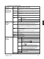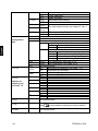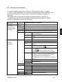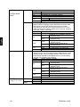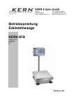
1
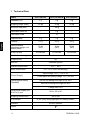
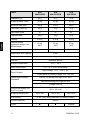
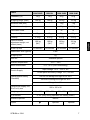
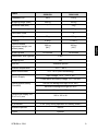
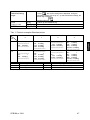
KERN & Sohn GmbH Ziegelei 1 D-72336 Balingen email: [email protected] Phone: +49-[0]7433- 9933-0 Fax: +49-[0]7433-9933-149 Internet: www.kern-sohn.com Operating instructions Stainless steel scale KERN SFB Version 2.4 12/2013 GB SFB-BA-e-1324 GB KERN SFB Version 2.4 12/2013 Operating instructions stainless steel scale Table of Contents 1 Technical Data ................................................................................................... 4 2 Appliance overview ......................................................................................... 10 2.1 Keyboard overview ...................................................................................................11 2.1.1 2.2 3 Numeric input via navigation keys ................................................................................... 12 Overview of displays .................................................................................................12 Basic Information (General) ........................................................................... 13 3.1 Proper use ................................................................................................................13 3.2 Improper Use ............................................................................................................13 3.3 Warranty ...................................................................................................................13 3.4 Monitoring of Test Resources ...................................................................................14 4 Basic Safety Precautions................................................................................ 14 4.1 Pay attention to the instructions in the Operation Manual .........................................14 4.2 Personnel training .....................................................................................................14 5 Transportation & Storage ............................................................................... 14 5.1 Testing upon acceptance ..........................................................................................14 5.2 Packaging / return transport .....................................................................................14 6 6.1 6.2 Unpacking and implantation .......................................................................... 15 Installation Site, Location of Use ...............................................................................15 Unpacking/implantation ............................................................................................15 6.2.1 Tripod ............................................................................................................................... 17 6.3 Mains connection ......................................................................................................20 6.4 Rechargeable battery operation ................................................................................20 6.5 Protection type IP65 .................................................................................................20 6.6 Adjustment................................................................................................................21 6.6.1 6.6.2 6.7 Linearization .............................................................................................................25 6.7.1 6.7.2 6.8 2 Verified models ................................................................................................................ 22 Non verifiable models ...................................................................................................... 24 Verified models ................................................................................................................ 25 Non-verified models ......................................................................................................... 26 Verification ................................................................................................................27 SFB-BA-e-1324 7 Operation ......................................................................................................... 28 7.1 Start-up .....................................................................................................................28 7.2 Switching Off ............................................................................................................28 7.3 Zeroing .....................................................................................................................28 7.4 Simple weighing........................................................................................................28 7.5 Switch-over weighing unit (only not verifiable models) ..............................................29 7.6 Weighing with tare ....................................................................................................30 7.7 Weighing with tolerance range .................................................................................30 7.7.1 7.7.2 Tolerance check for target weight .................................................................................... 31 Tolerance check for target quantity.................................................................................. 33 7.8 Manual totalizing .......................................................................................................35 7.9 Automatic adding-up .................................................................................................37 7.10 Parts counting ...........................................................................................................38 7.11 Animal weighing........................................................................................................39 7.12 Lock keyboard ..........................................................................................................40 7.13 Display background illumination................................................................................40 7.14 Automatic switch-off function “AUTO OFF“ ..................................................................41 8 Menu ................................................................................................................. 42 8.1 Overview non verifiable models ................................................................................43 8.2 Overview verified models ..........................................................................................45 9 Service, maintenance, disposal ..................................................................... 48 9.1 Cleaning ...................................................................................................................48 9.2 Service, maintenance ...............................................................................................48 9.3 Disposal ....................................................................................................................48 9.4 Error messages ........................................................................................................49 10 Data output RS 232C (optional) .................................................................. 50 10.1 Technical Data ..........................................................................................................50 10.2 Technical data ..........................................................................................................50 10.3 Printer mode .............................................................................................................50 10.4 Output log (continuous output)..................................................................................51 10.5 Remote control instructions ......................................................................................51 11 Instant help ................................................................................................... 52 12 Declaration of Conformity ........................................................................... 53 SFB-BA-e-1324 3 1 Technical Data KERN SFB 10K1HIP SFB 15K5HIPM SFB 20K2HIP 1g 5g 2g 10 kg 15 kg 20 kg Minimum load (Min) - 100 g - Verification value (e) - 5g - Verification class - III - 1g 5g 2g Linearity ±1g ±5g ±2g Recommended adjustment weight, not added (class) 10 kg (M1) 15 kg (M1) 20 kg (M1) 30 minutes 10 minutes 30 minutes Readability (d) Weighing range (max) Reproducibility Warm-up time Stabilization time (typical) Weighing unit Auto Off Ambient temperature Moist environment 2 sec. kg Available options -10°C – 40°C 0 % - 95 % (non-condensing) Input voltage 110 V – 230 V AC Electric Supply Power pack secondary voltage 12 V, 500 mA Rechargeable battery (Standard) Service life background light on for 40 h Service life background light off 80 h Charge time 12 h Dimensions display unit (B x D x H) mm Weighing surface mm IP protection Interface Tripod 4 266 x 165 x 96 300 x 240 IP 65 (Only during operation on battery power) RS 232 optional SFB-BA-e-1324 KERN SFB 30K10HIPM SFB 50K5HIP SFB 50K5LHIP SFB 50K-3XL Readability (d) 10 g 5g 5g 5g Weighing range (max) 30 kg 50 kg 50 kg 50 kg Minimum load (Min) 200 g - - - Verification value (e) 10 g - - - III - - - 10 g 5g 5g 5g Linearity ± 10 g ±5g ±5g ± 10 g Recommended adjustment weight, not added (class) 30 kg (M1) 50 kg (M1) 50 kg (M1) 50 kg (M1) 10 minutes 30 minutes 30 minutes 30 minutes Verification class Reproducibility Warm-up time Stabilization time (typical) 2 sec. Weighing unit kg Auto Off Available options -10°C – 40°C Ambient temperature Moist environment 0 % - 95 % (non-condensing) Input voltage 110 V – 230 V AC Electric Supply Power pack secondary voltage 12 V, 500 mA Rechargeable battery (Standard) Service life background light on for 40 h Service life background light off 80 h Charge time 12 h Dimensions display unit (B x D x H) mm Weighing surface mm IP protection Interface optional Tripod SFB-BA-e-1324 266 x 165 x 96 300 x 240 300 x 240 400 x 300 500 x 400 IP 65 (Only during operation on battery power) RS232 5 KERN SFB 60K20HIPM SFB 60K20LHIPM SFB 60K-2XLM Readability (d) 20 g 20 g 20 g Weighing range (max) 60 kg 60 kg 60 kg Minimum load (Min) 400 g 400 g 400 g Verification value (e) 20 g 20 g 20 g III III III 20 g 20 g 20 g Linearity ± 20 g ± 20 g ± 20 g Recommended adjustment weight, not added (class) 60 kg (M1) 60 kg (M1) 60 kg (M1) 10 minutes 10 minutes 10 minutes Verification class Reproducibility Warm-up time Stabilization time (typical) 2 sec. Weighing unit kg Auto Off Available options -10°C – 40°C Ambient temperature Moist environment 0 % - 95 % (non-condensing) Input voltage 110 V – 230 V, AC Electric Supply Power pack secondary voltage 12 V, 500 mA Rechargeable battery (Standard) Service life background light on for 40 h Service life background light off 80 h Charge time 8 h Dimensions display unit (B x D x H) mm Weighing surface mm IP protection 266 x 165 x 96 300 x 240 6 500 x 400 IP 65 (Only during operation on battery power) Interface optional Tripod 400 x 300 RS232 optional SFB-BA-e-1324 SFB 100K10HIP SFB 100K-2L SFB 100K-2HM SFB 100K-2LM 10 g 10 g 50 g 50 g 100 kg 100 kg 150 kg 150 kg Minimum load (Min) - - 1 kg 1 kg Verification value (e) - - 50 g 50 g Verification class - - III III 10 g 10 g 50 g 50 g Linearity ± 10 g ± 20 g ± 50 g ± 50 g Recommended adjustment weight, not added (class) 100 kg (M1) 100 kg (M1) 120 kg (M1) 150 kg (M1) 30 minutes 30 minutes 10 minutes 10 minutes KERN Readability (d) Weighing range (max) Reproducibility Warm-up time Stabilization time (typical) 2 sec. Weighing unit kg Auto Off Available options -10°C – 40°C Ambient temperature Moist environment 0 % - 95 % (non-condensing) Input voltage 110 V – 230 V, AC Electric Supply Power pack secondary voltage 12 V, 500 mA Rechargeable battery (Standard) Service life background light on for 40 h Service life background light off 80 h Charge time 12 h Dimensions display unit (B x D x H) mm Weighing surface mm IP protection 266 x 165 x 96 400 x 300 SFB-BA-e-1324 400 x 300 500 x 400 IP 65 (Only during operation on battery power) Interface optional Tripod 500 x 400 RS232 optional optional 7 KERN SFB 100K-2XL SFB 100K-2XLM SFB 120K50HIPM 10 g 50 g 50 g 100 kg 150 kg 120 kg Minimum load (Min) - 1 kg 1 kg Verification value (e) - 50 g 50 g Verification class - III III 10 g 50 g 50 g Linearity ± 20 g ± 50 g ± 50 g Recommended adjustment weight, not added (class) 100 kg (M1) 150 kg (M1) 120 kg (M1) 30 minutes 10 minutes 10 minutes Readability (d) Weighing range (max) Reproducibility Warm-up time Stabilization time (typical) 2 sec. Weighing unit kg Auto Off Available options -10°C – 40°C Ambient temperature Moist environment 0 % - 95 % (non-condensing) Input voltage 110 V – 230 V, AC Electric Supply Power pack secondary voltage 12 V, 500 mA Rechargeable battery (Standard) Service life background light on for 40 h Service life background light off 80 h Charge time 12 h Dimensions display unit (B x D x H) mm Weighing surface mm IP protection 266 x 165 x 96 650 x 500 IP 65 (Only during operation on battery power) Interface optional Tripod 8 400 x 300 RS232 optional optional SFB-BA-e-1324 SFB 200K-2XL SFB 300K-1LM 20 g 100 g 200 kg 300 kg Minimum load (Min) - 2 kg Verification value (e) - 100 g Verification class - III 20 g 100 g Linearity ± 40 g ± 100 g Recommended adjustment weight, not added (class) 200 kg (M1) 300 kg (M1) 30 minutes 10 minutes KERN Readability (d) Weighing range (max) Reproducibility Warm-up time Stabilization time (typical) Weighing unit Auto Off Ambient temperature Moist environment 2 sec. kg Available options -10°C – 40°C 0 % - 95 % (non-condensing) Input voltage 110 V – 230 V, AC Electric Supply Power pack secondary voltage 12 V, 500 mA Rechargeable battery (Standard) Service life background light on for 40 h Service life background light off 80 h Charge time 12 h Dimensions display unit (B x D x H) mm Weighing surface mm IP protection 266 x 165 x 96 650 x 500 IP 65 (Only during operation on battery power) Interface optional RS232 Tripod optional SFB-BA-e-1324 9 2 Appliance overview 1. 2. 3. 4. 5. 6. 7. 10 Battery status display Keyboard Weight display Tolerance tag, see chap. 7.7 Weighing unit Levelling screw Spirit level (underneath weighing platform) SFB-BA-e-1324 2.1 Keyboard overview Button Function Turn on/off Zeroing Navigation key Confirm entry Taring Navigation key At numeric input increase flashing digit Scroll forward in menu Display sum total Navigation key Digit selection to the right Add weighing value in summation memory Navigation key Digit selection to the left Calculate weighing data via interface C Delete Switch-over gross weight net weight ESC Back to menu/weighing mode Activate animal weighing function Activate weighing with tolerance limits Delete total added memory SFB-BA-e-1324 11 2.1.1 Numeric input via navigation keys Press current setting appears. The first digit is flashing and can be changed. If the first digit is not to be changed, press and the second digit will start flashing. Each time you press , the display unit jumps to the subsequent digit, returning to the first digit after the last digit has been pressed. To change the selected (flashing) digit, press repeatedly until the desired value appears. Then select by using additional digits and change these by using Finish entry with 2.2 . Overview of displays Display Significance Rechargeable battery very low STABLE Stability display ZERO Zero display GROSS Gross weight NET AUTO Automatic add-up enabled Kg Weighing unit M+ Adding LED + / / - 12 Net weight Indicators for weighing with tolerance limits SFB-BA-e-1324 3 Basic Information (General) 3.1 Proper use The balance you purchased is intended to determine the weighing value of material to be weighed. It is intended to be used as a “non-automatic balance”, i.e. the material to be weighed is manually and carefully placed in the centre of the weighing plate. As soon as a stable weighing value is reached the weighing value can be read. 3.2 Improper Use Do not use balance for dynamic weighing. In the event that small quantities are removed or added to the material to be weighed, incorrect weighing results can be displayed due to the “stability compensation“ in the balance. (Example: Slowly draining fluids from a container on the balance.) Do not leave permanent load on the weighing plate. This may damage the measuring system. Impacts and overloading exceeding the stated maximum load (max) of the weighing plate, minus a possibly existing tare load, must be strictly avoided. Balance may be damage by this. Never operate balance in explosive environment. The serial version is not explosion protected. The structure of the balance may not be modified. This may lead to incorrect weighing results, safety-related faults and destruction of the balance. The balance may only be used according to the described conditions. Other areas of use must be released by KERN in writing. 3.3 Warranty Warranty claims shall be voided in case Our conditions in the operation manual are ignored The appliance is used outside the described uses The appliance is modified or opened Mechanical damage or damage by media, liquids, natural wear and tear The appliance is improperly set up or incorrectly electrically connected The measuring system is overloaded SFB-BA-e-1324 13 3.4 Monitoring of Test Resources In the framework of quality assurance the measuring-related properties of the balance and, if applicable, the testing weight, must be checked regularly. The responsible user must define a suitable interval as well as type and scope of this test. Information is available on KERN’s home page (www.kern-sohn.com with regard to the monitoring of balance test substances and the test weights required for this. In KERN’s accredited DKD calibration laboratory test weights and balances may be calibrated (return to the national standard) fast and at moderate cost. 4 Basic Safety Precautions 4.1 Pay attention to the instructions in the Operation Manual Carefully read this operation manual before setup and commissioning, even if you are already familiar with KERN balances. 4.2 Personnel training The appliance may only be operated and maintained by trained personnel. 5 Transportation & Storage 5.1 Testing upon acceptance When receiving the appliance, please check packaging immediately, and the appliance itself when unpacking for possible visible damage. 5.2 Packaging / return transport Keep all parts of the original packaging for a possibly required return. Only use original packaging for returning. Prior to dispatch disconnect all cables and remove loose/mobile parts. Reattach possibly supplied transport securing devices. Secure all parts such as glass wind screen, weighing platform, power unit etc. against shifting and damage. 14 SFB-BA-e-1324 6 Unpacking and implantation 6.1 Installation Site, Location of Use The balances are designed in a way that reliable weighing results are achieved in common conditions of use. You will work accurately and fast, if you select the right location for your balance. On the installation site observe the following: Place the balance on a firm, level surface; Avoid extreme heat as well as temperature fluctuation caused by installing next to a radiator or in the direct sunlight; Protect the balance against direct draughts due to open windows and doors; Avoid jarring during weighing; Protect the balance against high humidity, vapors and dust; Do not expose the balance to strong humidity for extended periods. Nonpermitted condensation (condensation of air humidity on the appliance) may occur if a cold appliance is taken to a considerably warmer environment. In this case, acclimatize the disconnected appliance for ca. 2 hours at room temperature. Avoid static charge of goods to be weighed or weighing container. Being of protection type IP 67 as per DIN EN 60529, the weighing scale is suitable for short-term use in wet conditions. Major display deviations (incorrect weighing results) may be experienced should electromagnetic fields (e.g. due to mobile phones or radio equipment), static electricity accumulations or instable power supply occur. Change location or remove source of interference. 6.2 Unpacking/implantation Scope of delivery / serial accessories: Balance, see chap. 2 Transit Securing Mains adapter Rechargeable battery Instruction Manual Carefully remove the balance from the packaging, remove plastic cover, assemble the tripod and the display unit (see chap. 6.2.1) and setup balance at the intended workstation. SFB-BA-e-1324 15 Remove the transportation lock: 1. Models platform size 300 x 240 mm Remove the marked screws. 2. Models platform size 400 x 300 mm Remove the screw marked by the label . Attention: The sealed screws must not be unscrewed. Accurate weighing results require a weighing bridge with perfect horizontal alignment. During initial installation and after each change of work area it is necessary to level the weighing bridge. As the air bubble is located under the weighing plate, remove it. Level balance with foot screws until the air bubble of the water balance is in the prescribed circle. 16 SFB-BA-e-1324 6.2.1 Tripod Assemble example models platform size 300 x 240 mm: Attach the tripod to the platform acc. to fig. using the 4 screws [1], securing disks and washers. Ensure that the cable is not damaged nor squeezed. Screw-in support screw [2] till it is safely fixed. SFB-BA-e-1324 17 Remove display unit from holder, for that remove the turning knobs [3] on the side. Attach the tripod with the four raised counter-sunk head screws [4] and the nuts on the holder of the display unit. Re-attach and position display unit using the turning knobs [3]. 18 SFB-BA-e-1324 Scope of delivery models platform size 400 x 300 mm: SFB-BA-e-1324 Tripod tube Adapter display unit Tripod foot 19 6.3 Mains connection Power is supplied via the external mains adapter. The stated voltage value must be the same as the local voltage. Only use original KERN mains adapters. Using other makes requires consent by KERN. 6.4 Rechargeable battery operation Before the first use, the battery should be charged by connecting it to the mains power supply for at least 12 hours. The symbol appearing on the weight display indicates that the battery is getting low. Approximately 10 h of instrument usage are left; afterwards it will shut off automatically. Use the supplied battery charger for charging the battery. Charge status of rechargeable battery is indicated by the LED display. red: Voltage has dropped below prescribed minimum. green: Rechargeable battery is completely charged yellow: Charging storage battery To save battery life, you can enable the automatic switch-off function "AUTO OFF", see chap. 7.14. 6.5 Protection type IP65 Designed for temporary contact with liquids. Use a damp cloth for cleaning. Dustproof. IP65 protection is only ensured during operation on battery power. 20 SFB-BA-e-1324 6.6 Adjustment As the acceleration value due to gravity is not the same at every location on earth, each display unit with connected weighing plate must be coordinated - in compliance with the underlying physical weighing principle - to the existing acceleration due to gravity at its place of location (only if the weighing system has not already been adjusted to the location in the factory). This adjustment process must be carried out for the first commissioning, after each change of location as well as in case of fluctuating environment temperature. To receive accurate measuring values it is also recommended to adjust the display unit periodically in weighing operation. In weighing systems with a resolution of < 15 000 dividing steps an adjustment is recommended. In weighing systems with a resolution of > 15 000 dividing steps a linearisation is recommended (see chap. 6.6). Prepare the required adjustment weight. The weight to be used depends on the capacity of the scale. Carry out adjustment as near as possible to the scale’s maximum weight. Info about test weights can be found on the Internet at: http://www.kern-sohn.com. Observe stable environmental conditions. Stabilisation requires a certain warm-up time. SFB-BA-e-1324 21 6.6.1 Verified models In verified weighing systems the menu item for adjustment „P2 mode“ is blocked. To override the blocked access you will have to destroy the seal before calling up the menu and to short-circuit the two contacts on the circuit board [K2], using a jumper (See chap.6.7). Attention: After destruction of the seal the weighing system must be re-verified by an authorised agency and a new verification wire/seal mark fitted before it can be reused for applications subject to verification. Call up menu: 1. Switch-on balance and during the selftest press . 2. Press , , subsequently, the first menu block „PO CHK“ will be displayed. 3. Press repeatedly until „P2 mode“ will be displayed. 4. Press and select the set weighing scales type by . = Single-range balance = Dual range balance = Multi-interval balance 5. Acknowledge with 6. Press repeatedly until „CAL“ will be displayed. 7. Confirm with 22 . and select setting „noLin“ by . SFB-BA-e-1324 How to carry out an adjustment: Confirm menu setting „noLin“ by . Ensure that there are no objects on the weighing plate. Wait for stability display, then press . The currently set adjustment weight will be displayed. To change by using the navigation buttons (see chap. 2.1.1) select the desired setting, the active digit is flashing. Acknowledge with . Carefully place adjusting weight in the centre of the weighing plate. Wait for stability display, then press . After the adjustment the balance will carry out a self-test. Remove adjusting weight during selftest, balance will return into weighing mode automatically. An adjusting error or incorrect adjusting weight will be indicated by the error message; repeat adjustment procedure. SFB-BA-e-1324 23 6.6.2 Non verifiable models Call up menu: 1. Switch-on balance and during the selftest press 2. Press subsequently , „PO CHK“ will be displayed. 3. Press , . the first menu block repeatedly until „P3 CAL“ will be displayed. 4. Confirm with appears. repeatedly until „CAL“ ; press 5. Acknowledge using , the current setting is displayed. Press to confirm; press to select setting. noLin = adjustment LineAr = linearization, see chap. 6.6 How to carry out adjustment: Confirm menu setting „noLin“ by . Ensure that there are no objects on the weighing plate. Wait for stability display, then press . The currently set adjustment weight will be displayed. To change by using the navigation buttons (see chap. 2.1.1) select the desired setting, the active digit is flashing. Acknowledge with . Carefully place adjusting weight in the centre of the weighing plate. Wait for stability display, then press . After the adjustment the balance will carry out a self-test. Remove adjusting weight during selftest, balance will return into weighing mode automatically. An adjusting error or incorrect adjusting weight will be indicated by the error message; repeat adjustment procedure. 24 SFB-BA-e-1324 6.7 Linearization Linearity shows the greatest deviation of a weight display on the scale to the value of the respective test weight according to plus and minus over the entire weighing range. If linearity deviation is discovered during a testing instrument control, you can improve this by means of linearization. In balances with a resolution of > 15 000 dividing steps carrying out a linearisation is recommended. Carrying out linearization is restricted to specialist staff possessing well acquainted with the workings of weighing scales. The test weights to be used must be adapted to the weighing scale’s specifications; see chapter “testing instruments control”. Observe stable environmental conditions. Stabilisation requires a certain warm-up time. After successful linearisation you will have to carry out calibration; see chapter “testing instruments control”. The adjustment is locked for verified balances. To disable the access lock, destroy the seal and actuate the adjustment switch. Position of the adjustment switch see chap. 6.7 6.7.1 Verified models Menu item P2 modeCalCall up liner, see chap. 6.5.1 Confirm by , the password query „Pn“ will be displayed. Press subsequently , , or , , Ensure that there are no objects on the weighing pan. Wait for stability display, then press . . When “Ld 1“ is displayed, put the first adjustment weight (1/3 max) carefully in the centre of the weighing platform. Wait for stability display, then press . When “Ld 2“ is displayed, put the second adjustment weight (2/3 max) carefully in the centre of the weighing platform. Wait for stability display, then press . When “Ld 3“ is displayed, put the third adjustment weight (max) carefully in the centre of the weighing platform. Wait for stability display, then press . After linearisation the balance will carry out a self-test. Remove adjusting weight during selftest, balance will return into weighing mode automatically. SFB-BA-e-1324 25 6.7.2 Non-verified models Call-up menu item P3 CALCalLiner, see chap. 6.5.1 Confirm by , the password query „Pn“ will be displayed. Press subsequently , , or , , Ensure that there are no objects on the weighing pan. Wait for stability display, then press . . When “Ld 1“ is displayed, put the first adjustment weight (1/3 max) carefully in the centre of the weighing platform. Wait for stability display, then press . When “Ld 2“ is displayed, put the second adjustment weight (2/3 max) carefully in the centre of the weighing platform. Wait for stability display, then press . When “Ld 3“ is displayed, put the third adjustment weight (max) carefully in the centre of the weighing platform. Wait for stability display, then press . After a successful linearisation the balance will carry out a self-test. Remove adjusting weight during selftest, balance will return into weighing mode automatically. 26 SFB-BA-e-1324 6.8 Verification General introduction: According to EU directive 90/384/EEC or 2009/23EG balances must be officially verified if they are used as follows (legally controlled area): a) For commercial transactions if the price of goods is determined by weighing. b) For the production of medicines in pharmacies as well as for analyses in the medical and pharmaceutical laboratory. c) For official purpose. d) For manufacturing final packages. In cases of doubt, please contact your local trade in standard. Verification notes: An EU Qualification Approval is in existence for verified weighing systems. If a balance is used where obligation to verify exists as described above, it must be verified and re-verified at regular intervals. Reverification is carried out according to the relevant national statutory regulations. The validity for verification of balances in Germany is e.g. 2 years. The legal regulation of the country where the balance is used must be observed! Verification of the weighing system is invalid without the "seal". Notes on verified models Access to conductor plate: Remove seal Open display unit The application of the display unit as a weighing system able to be verified requires that the contacts of the circuit board are short-circuited with the help of a jumper [K1]. For non verifiable models remove the jumper. To adjust, short-circuit the contacts of the circuit board, using a jumper [K2]. [K1] SFB-BA-e-1324 [K2] 27 7 Operation 7.1 Start-up Press , and the instrument will carry out a self-test. The instrument is ready for weighing when a weight display appears. 7.2 Switching Off Press until the display disappears. 7.3 Zeroing Resetting to zero corrects the influence of light soiling on the weighing plate. Resetting range ± 2 % max. The instrument comprises an automatic zero setting function, however, the instrument can be reset to zero whenever needed as described below. Remove load from weighing system Press 7.4 , and the zero display as well as the ZERO indicator will appear. Simple weighing Place goods to be weighed on balance. Wait for stability display STABLE. Read weighing result. Overload warning Overloading exceeding the stated maximum load (max) of the device, minus a possibly existing tare load, must be strictly avoided. The instrument may be damaged by overloading. Exceeding of maximum load is indicated by “----“ as well as a signal sound. Remove load from weighing system or reduce preload. 28 SFB-BA-e-1324 7.5 Switch-over weighing unit (only not verifiable models) How to enable weighing units: Call-up menu item P5 Unt, see chap. 8 Press and the first weighing unit with the current setting will be displayed. To enable [on] / disable [off] the displayed weighing unit, press . Acknowledge with will be displayed. . The next unit with the current setting To enable [off] / disable [on] the displayed weighing unit, press . Acknowledge with . Repeat sequence for each weighing unit. Note: „tj“ and „Hj“ cannot be activated at the same time, only either ... or ... . Return to weighing mode using Switch-over weighing unit: Keep pressed, the display changes over to the weighing units activated before (e.g. kg lb) SFB-BA-e-1324 29 7.6 Weighing with tare Deposit weighing vessel. After successful stop check press the The zero display and the indicator NET appear. button. The weight of the container is now internally saved. Weigh the material, the net weight will be indicated. The weight of the weighing container will be displayed as a minus number after removing the weighing container. The tare procedure can be repeated as many times as necessary, for example with initial weighing of several components for a mix (add-on weighing). The limit is reached when the taring range (see type plate) capacity is full. Switch between gross weight and net weight by pressing the key. To delete the tare value, remove load from weighing plate and press . 7.7 Weighing with tolerance range You may determine an upper and lower limit for weighing with tolerance limits in order to ensure that the weighed load remains exactly within the fixed tolerance limits. During tolerance checks such as dispensing, portioning and sorting, the instrument will indicate any lower deviation or exceeding of limits with the help of a visual signal or audio sound. Acoustic signal: The audio sound depends on the setting of the menu block “BEEP“. Options: 30 no Acoustic signal turned off ok Acoustic signal sounds when load is within tolerance limits ng Acoustic signal sounds when load is beyond tolerance limits SFB-BA-e-1324 Optical signal: Three colour pilot lamps indicate whether load is within the two tolerance limits. The signal lamps provide the following information: + Goods to be weighed above tolerance limit Red signal lamp glowing Goods to be weighed within tolerance range Green signal lamp glowing Goods to be weighed below tolerance limit Red signal lamp glowing - Settings for tolerance weighing may be set either by calling up menu block “P0 CHK“ (See chap. 8) or by applying the faster option of pressing the key combination 7.7.1 Tolerance check for target weight Settings Press Press Press and at the same time in weighing mode. until the display for entering the lower limit value appears. , the current setting will be displayed. To enter the lower limit, e. g. 1000 Kg, press the navigation keys (See chap. 2.1.1); the currently enabled digit will be flashing. Confirm input by Press . repeatedly until is displayed. Press , the current setting for the upper limit will be displayed. SFB-BA-e-1324 31 Press the navigation keys (See chap. 2.1.1) to enter the upper limit, e.g. 1,100 kg; the currently enabled digit will be flashing. Confirm input by Press . repeatedly until is displayed. Press and the current setting for the acoustic signal will be shown. Select desired setting (no, ok, ng) by Confirm input by . . Press ; weighing system is in tolerance weighing mode. From here evaluation takes place whether the goods to be weighed are within the two tolerance limits. Weighing with tolerance range Tare when using a weighing container. Put on goods to be weighed, tolerance control is started. The signal lights indicate whether the load is within the two set limits. Load below specified tolerance Load within specified tolerance Red signal light next to „-“ ON illuminated Green signal light next to „„ illuminated Load exceeds specified tolerance Red signal light next to „+“ ON illuminated The tolerance control is not active when the weight is under 20d. To delete limits, enter “00.000 kg“. 32 SFB-BA-e-1324 7.7.2 Tolerance check for target quantity Settings Press Press Press and at the same time in weighing mode. until the display for entering the lower limit value appears. , the current setting will be displayed. To enter the lower limit, e. g. 75 items, press the navigation buttons (see chap. 2.1.1); the currently enabled digit will be flashing. Confirm input by Press . repeatedly until is displayed. Press , the current setting for the upper limit will be displayed. To enter the upper limit, e. g. 100 items, press the navigation buttons (see chap. 2.1.1); the currently enabled digit will be flashing. Confirm input by Press . repeatedly until is displayed. Press and the current setting for the acoustic signal will be shown. Select desired setting (no, ok, ng) by Confirm input by SFB-BA-e-1324 . . 33 Press ; weighing system is in tolerance weighing mode. From here evaluation takes place whether the goods to be weighed are within the two tolerance limits. Weighing with tolerance range Set item weight, see chap. 7.10. Tare when using a weighing container. Put on goods to be weighed, tolerance control is started. The signal lights indicate whether the load is within the two set limits. Load below specified tolerance Load within specified tolerance Red signal light next to „-“ ON illuminated Green signal light next to „„ illuminated Load exceeds specified tolerance Red signal light next to „+“ ON illuminated The tolerance control is not active when the weight is under 20d. To delete limits, enter „00000 PCS“. 34 SFB-BA-e-1324 7.8 Manual totalizing With this function the individual weighing values are added into the summation memory by pressing and edited, when an optional printer is connected. Menu settings: „P1 COM“ or „P2 COM“ „MODE“ „PR2““, see chap. 8 The totalisation function is not active when the weight is under 20d. Add up: Place goods to be weighed A. Wait until the stability display STABLE appears, then press . The weight value will be saved and a printout received if an optional printer is connected. Remove the weighed good. More weighed goods can only be added when the display = zero. Place goods to be weighed B. Wait until the stability display appears, then press . The weight value will be added to the summation memory and possibly printed. The number of weighing processes followed by the total weight will be shown for 2 sec. Add more weighed goods as described before. Please note that the weighing system must be unloaded between the individual weighing procedures. This process may be repeated 99 times or till such time as the capacity of the weighing system has been exhausted. Display and output sum „Total“: Press and the number of weighings followed by the total weight will be shown for 2 sec. To receive a printout, press SFB-BA-e-1324 during this display. 35 Delete weighing data: Press deleted. and at the same time. The data in the summation memory are Printout example KERN YKB-01N, verified weighing system: Menu setting „P1 COM“ or „P2 COM“ „Lab 2“ / Prt 7“ 36 1 First weighing 2 Second weighing 3 Third weighing 4 Number of weighings / total Menu setting „P1 COM“ or „P2 COM“ „Lab 0“ / Prt 0“ + SFB-BA-e-1324 7.9 Automatic adding-up With this function the individual weighing values are automatically added into the summation memory when the balance is unloaded without pressing when an optional printer is connected. and edited, Menu settings: „P1 COM“ or „P2 COM“ „MODE“ „AUTO““, see chap. 8 Indicator AUTO is displayed. Add up: Place goods to be weighed A. After the standstill control sounds a signal tone. The weighing value is added to the summation memory, followed by printing. Remove the weighed good. More weighed goods can only be added when the display = zero. Place goods to be weighed B. After the standstill control sounds a signal tone. The weighing value is added to the summation memory, followed by printing. The number of weighings, followed by the total weight, will be shown for 2 sec. Add more weighed goods as described before. Please note that the weighing system must be unloaded between the individual weighing procedures. This process may be repeated 99 times or till such time as the capacity of the weighing system has been exhausted. Display and delete the weighing data, as well as printout examples see chap. 7.8. SFB-BA-e-1324 37 7.10 Parts counting Before the balance can count parts, it must know the average part weight (i.e. reference). Proceed by putting on a certain number of the parts to be counted. The balance determines the total weight and divides it by the number of parts, the socalled reference quantity. Counting is then carried out on the basis of the calculated average piece weight. As a rule: The higher the reference quantity the higher the counting exactness. In weighing mode , press and hold until the message „P 10“ appears that is used to set the reference quantity. Use to set the desired reference quantity (such as 100), options include P 10, P 20, P 50, P100, P 200. Place as many items to be counted (such as 100 items) as demanded by the set reference quantity and confirm by The weighing scales calculate the reference weight. The current quantity (such as 100 items) will be displayed. Remove reference weight. The balance is from now in parts counting mode counting all units on the weighing plate. Back to Weighing mode by 38 . SFB-BA-e-1324 7.11 Animal weighing The animal weighing function is ideal for unstable loads. The weighing system calculates and displays a stable mean average from several weighing values. The animal weighing program may either be enabled by calling up menu block “P3 OTH“ or “P4 OTH“ „ANM“ „ON“ (See chap. 8) or by using the faster option of a key combination. The indicator shows HOLD as long as the animal weighing function remains enabled. Place the load onto the weighing system and wait until it is fairly stable. Press and at the same time, a signal sounds, meaning that the animal weighing function is enabled. During the calculation of a mean average you can add or remove loads as the mean average will be continuously updated. To disable the animal weighing function press SFB-BA-e-1324 and at the same time. 39 7.12 Lock keyboard Go to menu item “P3 OTH“ or “P4 OTH“ „LOCK“, see chap. 8, and enable/disable the keyboard interlock. The enabled function will be locked after 10 minutes of inactivity. “K-LCK“ will be displayed as soon as a key is pressed. To cancel locking, keep pressed LCK“ appears. , and at the same time (2s) until “U 7.13 Display background illumination Keep pressed (3s) until “setbl“ appears. Press again and the current setting will be displayed. Use to select desired setting. bl on Background lighting is on continuously bl off Background illumination off bl Auto Automatic background illumination on when weighing plate is loaded Save entry by 40 or cancel using . SFB-BA-e-1324 7.14 Automatic switch-off function “AUTO OFF“ The instrument will switch off automatically after a set time when the display unit or weighing bridge has been idle. Keep pressed (3s) until “setbl“ appears. Call up AUTO OFF function using Press Use - current setting appears. to select desired setting. of 0 AUTO OFF - of 3 Weighing system will be turned off after 3 min. of 5 Weighing system will be turned off after 5 min. of 15 Weighing system will be turned off after 15 min. of 30 Weighing system will be turned off after 30 min. Save entry by SFB-BA-e-1324 function disabled or cancel using . 41 8 Menu Navigation in the menu: Call up menu Switch-on balance and during the selftest press . Press , , subsequently, the first menu block „PO CHK“ will be displayed. Select menu block Select setting With help of , the individual menu items can be selected one after the other. Confirm selected menu item by pressing current setting will be displayed. . The Change settings To change to the available settings, press the navigations keys as described in chap. 2.1. Acknowledge setting / exit the menu Either save by pressing Return to weighing mode Press 42 or cancel by pressing . repeatedly to exit menu. SFB-BA-e-1324 8.1 Overview non verifiable models Menu block Main menu PO CHK Weighing with tolerance range, see chap. 7.7 Menu item Submenu SET H Available settings / explanation Upper limit value „Tolerance check weighing“, input see chap. 7.7.1 SET LO Lower limit value „Tolerance check weighing“, input see chap. 7.7.1 PCS H Upper limit value „Tolerance check counting“, input see chap. 7.7.2 PCS L Lower limit value „Tolerance check counting“, input see chap. 7.7.2 Acoustic signal for weighing with tolerance range no switched off ok Audio sound when load is within tolerance limits BEEP nG Audio sound when load is beyond tolerance limits P1 REF A2n0 Zero point settings Automatic zero point correction (Autozero) by changing the display, digits selectable (0.5d, 1d, 2d, 4d) 0AUto Zero setting range Load range where the display after switching-on the balance is set to zero. Selectable 0, 2, 5, 10, 20, 50, 100 % 0rAGE Zero setting range Load range where the display is set to zero by pressing . Selectable 0, 2, 4, 10 , 20* , 50, 100%. P2 COM 0tArE Automatic taring „on / off“, taring range adjustable in menu item „0Auto“. SPEEd Not documented Zero Zero point setting Continuous data output CONT One output for stable weighing value ST1 Continuous data output of stable weighing STC values PR1 Output after pressing Manual totalizing, see chap. 7.8. PR2 MODE Interface parameter AUTO* Press and the weighing value will be added to the summation memory and issued. For automatic add-up see chap. 7.9. This function is used to issue and add individual weighing values automatically to the summation memory on unloading of weighing scale. BAUD SFB-BA-e-1324 ASK For remote control commands, see chap. 10.4 wirel kit 1 Not documented Available Baudrate: 600, 1200, 2400, 4800, 9600* 43 Pr PTYPE Lab 7E1 7o1 8n1* tPUP* LP50 Lab x (Lab 0*) Prt Prt x 7 bits, even parity 7 bits, odd parity 8 bits, no parity Standard printer setting Not documented For data output format, see chap.8.2, tab. 1 (Prt 0*) LAnG P3 CAL Configuration data COUNT DECI DUAL CAL GrA P4 OTH LOCK ANM P5 Unt Switch-over weighing unit, see chap. 7.5 kg g lb oz tJ HJ P6 xcl eng* Standard settings English chn Display internal resolution Position of the decimal dot Setting balance type, capacity (Max) and readability (d) off Single-range balance R1 inc Readability R1 cap Capacity on Dual range balance R1 inc Readability 1st weighing range R1 cap Capacity 1st weighing range R2 inc Readability 2nd weighing range R2 cap Capacity 2nd weighing range noLin For adjustment, see chap. 6.5.2 Liner For linearization, see chap. 6.6.2 Not documented on Keyboard lock enabled, see chap. 7.12 off* Keyboard lock disabled on Animal weighing enabled, see chap. 7.11 off* Animal weighing disabled on* off on off* on off* on off* on off on off Not documented P7 rst Use P8 uwb to reset balance settings to factory default. Not documented Factory settings are marked by *. 44 SFB-BA-e-1324 8.2 Overview verified models In verified weighing systems the access to „P2 mode and „P4 tAr“ is locked. In order to unlock the access, the seal must be destroyed and both contacts of the printed circuit board [K2] must be short-circuited by a jumper, see chap. 6.11. Attention: After destruction of the seal the weighing system must be re-verified by an authorised agency and a new verification wire/seal mark fitted before it can be reused for applications subject to verification. Menu block Main menu PO CHK Weighing with tolerance range, see chap. 7.7 Menu item Submenu SET H Available settings / explanation Upper limit value „Tolerance check weighing“, input see chap. 7.7.1 SET LO Lower limit value „Tolerance check weighing“, input see chap. 7.7.1 PCS H Upper limit value „Tolerance check counting“, input see chap. 7.7.2 PCS L Lower limit value „Tolerance check counting“, input see chap. 7.7.2 BEEP no ok ng P1 COM MODE CONT ST1 STC Interface parameter Acoustic signal for weighing with tolerance range switched off Audio sound when load is within tolerance limits Audio sound when load is beyond tolerance limits Continuous data output One output for stable weighing value Continuous data output of stable weighing values PR1 PR2 AUTO ASK baud Pr PtYPE Lab Prt SFB-BA-e-1324 Output after pressing Manual totalizing, see chap. 7.8 Press and the weighing value will be added to the summation memory and issued. For automatic totalizing see chap. 7.9. This function is used to issue and add individual weighing values automatically to the summation memory on unloading of weighing scale. For remote control commands, see chap. 10.4 wireless Not documented Kit 1 Available Baudrate: 600, 1200, 2400, 4800, 9600 7 bits, even parity 7E1 7 bits, odd parity 7o1 8 bits, no parity 8n1 Standard printer setting tPUP Not documented LP50 Lab x Prt x Details see following table 1 45 P2 mode SiGr Single-range balance COUNT DECI Div. CAP Konfigurationsdaten CAL GrA dUAL 1 Display internal resolution Position of the decimal dot Readability [d] / verification value[s] Balance capacity [Max] noLin Adjustment, see chap. 6.5 LinEr Linearisation, see chap. 6.7 Not documented Dual range balance Balance with two weighing ranges and different maximum load and weighing ranges and interval sizes but only one loadsupporting pan, whereby each range extends from zero to the respective maximum capacity. When load is removed, weighing scales will remain in 2nd range. COUNT Display internal resolution DECI Position of the decimal dot Readability [d] / verification value [e] div 1 1. weighing range div. Readability [d] / verification value [e] div 2 2. weighing range Weighing scale capacity [max] CAP 1 1. Weighing range CAP Weighing scale capacity [max] CAP 2 2. Weighing range noLin Adjustment, see chap. 6.5.1 CAL LinEr For linearization, see chap. 6.6.1 GrA Not documented dUAL 2 P3 OTH s. Kap. 7.11 / 7.12 LOCK ANM 46 Multi-interval balance Weighing scales with one weighing range subdivided into partial weighing ranges, each providing a different scale interval. The scale interval depends on the applied load and is automatically changed during loading and unloading. COUNT Display internal resolution DECI Position of the decimal dot Readability [d] / verification value [e] div 1 1. weighing range div. Readability [d] / verification value [e] div 2 2. weighing range Weighing scale capacity [max] CAP 1 1. Weighing range CAP Weighing scale capacity [max] CAP 2 2. Weighing range noLin Adjustment, see chap. 6.5.1 CAL LinEr Linearisation, see chap. 6.6.1 GrA Not documented on Keyboard lock enabled off Keyboard lock disabled on Animal weighing enabled off Animal weighing disabled SFB-BA-e-1324 P4 tAr Restricted taring range Press , the current setting will be displayed. Using the navigation buttons (see chap. 2.1.1) select the desired setting, the active digit is flashing. Confirm input by P5 St St on St off 7.5, 15, 30 Follow up tare P6 SP . Follow up tare switched on Follow up tare switched off Not documented Tab. 1. Printout examples Standard printer Lab 0 Prt 2 ******************* GS: 5.000kg ******************* ******************* NT: 5.000kg TW: 5.000kg GW: 10.000kg ******************* ********************** GS: 5.000kg TOTAL: 10.000kg ********************** ******************* No.: 1 GS: 5.000kg ******************* ******************* No.: 1 NT: 5.000kg TW: 5.000kg GW: 10.000kg ******************* ********************** No.: 1 GS: 5.000kg TOTAL: 10.000kg ********************** 0~3 4~7 GS / GW NT TW 1 Gross weight Net weight Tare weight SFB-BA-e-1324 NO TOTAL 3 ********************** NT: 5.000kg TW: 5.000kg GW: 10.000kg TOTAL: 10.000kg ********************** ********************** No.: 1 NT: 5.000kg TW: 5.000kg GW: 10.000kg TOTAL: 10.000kg ********************** Number weighing processes Total of all individual weighings 47 9 Service, maintenance, disposal 9.1 Cleaning Before cleaning, disconnect the appliance from the operating voltage. Cleaning is possible by water jet and short-time immersion. Do not apply aggressive detergents (solvents etc.). 9.2 Service, maintenance The appliance may only be opened by trained service technicians who are authorized by KERN. Before opening, disconnect from power supply. 9.3 Disposal Disposal of packaging and appliance must be carried out by operator according to valid national or regional law of the location where the appliance is used. 48 SFB-BA-e-1324 9.4 Error messages Error message Description ----- Possible causes Maximum load exceeded Unload weighing system or reduce preload. Err 1 Incorrect data input Follow format “yy:mm:dd“ Err 2 Incorrect time entry Follow format “hh:mm:ss“ Err 4 Zeroing range exceeded due to switching-on balance or Object on the weighing plate - - ol - - Overload when zeroing pressing max) (normally 4% Err 5 Keyboard error Err 6 Value outside the A/D changer range Weighing plate not installed Damaged weighing cell Damaged electronics Err 9 Stability display does not appear Check the environmental conditions. Err 10 Communication error No data Err 15 Gravitation error Range 0.9 ~ 1.0 Err 17 Taring range exceeded Reduce load Adjustment error Repeat adjustment. Printer error Check communication parameters Battery very low Recharge battery Fai l h / Fai l l Err P Ba lo / Lo ba Should other error messages occur, switch balance off and then on again. If the error message remains inform manufacturer. SFB-BA-e-1324 49 10 Data output RS 232C (optional) Weighing data can be issued according to menu settings either via the RS 232C interface or by pressing via the interface. This data exchange is asynchronous using ASCII - Code. The following conditions must be met to provide successful communication between the weighing balance and the printer. Use a suitable cable to connect the weighing balance to the interface of the printer. Faultless operation requires an adequate KERN interface cable. Communication parameters (baud rate, bits and parity) of balance and printer must match. For detailed description of interface parameters see chap. 8, menu block „P1 COM“ or „P2 COM“. 10.1 Technical Data 10.2 Technical data Connection 9 pin d-subminiature bushing Pin 2 input Pin 3 output Pin 5 signal earth Baud rate Optional 600/1200/2400/4800/9600 Parity 8 bits, no parity / 7 bits, even parity / 7 bits, odd parity 10.3 Printer mode Printout examples (KERN YKB-01N): Weighing ST, GS 50 1.000kg SFB-BA-e-1324 Symbols: ST Stable value US Instable value GS / GW Gross weight NT Net weight TW Tare weight NO Number weighing processes TOTAL Total of all individual weighings <lf> Space line <lf> Space line Counting **************************** PCS 100 **************************** 10.4 Output log (continuous output) Weighing HEADER1: ST=STABLE, US=UNSTABLE HEADER2: NT=NET, GS=GROSS 10.5 Remote control instructions Command Function Printout examples S Stable weighing value for the weight is sent via the RS232 interface ST,GS 1.000KG W Weighing value for the weight (stable or unstable) is sent via the RS232 interface US,GS 1.342KG ST,GS 1.000KG T No data are sent, the balance carries out the tare function. - Z No data are sent, the zero-display appears. - P Quantity will be sent via the RS232interface SFB-BA-e-1324 10PCS 51 11 Instant help In case of an error in the program process, briefly turn off the balance and disconnect from power supply. The weighing process must then be restarted from the beginning. Help: Fault The displayed weight does not glow. Possible cause The balance is not switched on. Mains power failure (mains cable defective). Power supply interrupted. (Rechargeable) batteries are inserted incorrectly or empty No (rechargeable) batteries inserted. The displayed weight is permanently changing Draught/air movement Table/floor vibrations Weighing plate has contact with other objects. Electromagnetic fields / static charging (choose different location/switch off interfering device if possible) The weighing result is obviously incorrect The display of the balance is not at zero Adjustment is no longer correct. Great fluctuations in temperature. Warm-up time was ignored. Electromagnetic fields / static charging (choose different location/switch off interfering device if possible) Should other error messages occur, switch balance off and then on again. If the error message remains inform manufacturer. 52 SFB-BA-e-1324 12 Declaration of Conformity KERN & Sohn GmbH D-72322 Balingen-Frommern Postbox 4052 E-Mail: [email protected] Phone: 0049-[0]7433- 9933-0 Fax: 0049-[0]7433-9933-149 Internet: www.kern-sohn.de Declaration of conformity EC Declaration of Conformity EC- Déclaration de conformité EC-Dichiarazione di conformità EC- Declaração de conformidade EC-Deklaracja zgodności D EN CZ E F I NL P PL RUS Konformitätserklärung Declaration of conformity Prohlášení o shode Declaración de conformidad Déclaration de conformité Dichiarazione di conformità Conformiteitverklaring Declaração de conformidade Deklaracja zgodności Заявление о соответствии EC-Declaration of -Conformity EC-Declaración de Conformidad EC-Conformiteitverklaring EC- Prohlášení o shode EC-Заявление о соответствии Wir erklären hiermit, dass das Produkt, auf das sich diese Erklärung bezieht, mit den nachstehenden Normen übereinstimmt. We hereby declare that the product to which this declaration refers conforms to the following standards. Tímto prohlašujeme, že výrobek, kterého se toto prohlášení týká, je v souladu s níže uvedenými normami. Manifestamos en la presente que el producto al que se refiere esta declaración está de acuerdo con las normas siguientes Nous déclarons avec cela responsabilité que le produit, auquel se rapporte la présente déclaration, est conforme aux normes citées ci-après. Dichiariamo con ciò che il prodotto al quale la presente dichiarazione si riferisce è conforme alle norme di seguito citate. Wij verklaren hiermede dat het product, waarop deze verklaring betrekking heeft, met de hierna vermelde normen overeenstemt. Declaramos por meio da presente que o produto no qual se refere esta declaração, corresponde às normas seguintes. Niniejszym oświadczamy, że produkt, którego niniejsze oświadczenie dotyczy, jest zgodny z poniższymi normami. Мы заявляем, что продукт, к которому относится данная декларация, соответствует перечисленным ниже нормам. Electronic Balance: KERN KFB-TM, KFN-TM, BFB, BFN, IFB, NFB, SFB, UFA, UFB, UFN EU Directive 2004/108/EC 2006/95/EC Datum Standards EN55022: 2006 A1:2007 EN61000-3-3:1995+A1:2001+A2:2005 EN55024: 1998+A1:2001+A2:2003 EN 60950-1:2006 EN 60065:2002+A1:2006 08.04.2013 Signatur Date Signature Ort der Ausstellung Place of issue 72336 Balingen Albert Sauter KERN & Sohn GmbH Geschäftsführer Managing director KERN & Sohn GmbH, Ziegelei 1, D-72336 Balingen, Tel. +49-[0]7433/9933-0 Fax +49-[0]7433/9933-149, E-Mail: [email protected], Internet: www.kern-sohn.com SFB-BA-e-1324 53