1
L−force Geared Motors
Ä.IPQä
BA 12.0023−EN
.IPQ
Operating Instructions
GLL
GST, GFL, GKS/GKL, GKR, GSS
Gearbox
l
,
Please read these instructions before you start working!
Follow the enclosed safety instructions.
0Fig. 0Tab. 0
2
l
BA 12.0023−EN 7.0
Contents
1
2
3
4
5
i
About this documentation . . . . . . . . . . . . . . . . . . . . . . . . . . . . . . . . . . . . . . . . . . . . . . . . . .
5
1.1
Document history . . . . . . . . . . . . . . . . . . . . . . . . . . . . . . . . . . . . . . . . . . . . . . . . . . . .
6
1.2
Conventions used . . . . . . . . . . . . . . . . . . . . . . . . . . . . . . . . . . . . . . . . . . . . . . . . . . . .
7
1.3
Terminology used . . . . . . . . . . . . . . . . . . . . . . . . . . . . . . . . . . . . . . . . . . . . . . . . . . . .
7
1.4
Notes used . . . . . . . . . . . . . . . . . . . . . . . . . . . . . . . . . . . . . . . . . . . . . . . . . . . . . . . . . .
8
Safety instructions . . . . . . . . . . . . . . . . . . . . . . . . . . . . . . . . . . . . . . . . . . . . . . . . . . . . . . . . .
9
2.1
General safety instructions for drive components . . . . . . . . . . . . . . . . . . . . . . . . . .
9
2.2
Application as directed . . . . . . . . . . . . . . . . . . . . . . . . . . . . . . . . . . . . . . . . . . . . . . . .
12
2.3
Improper use . . . . . . . . . . . . . . . . . . . . . . . . . . . . . . . . . . . . . . . . . . . . . . . . . . . . . . . .
12
2.4
Residual hazards . . . . . . . . . . . . . . . . . . . . . . . . . . . . . . . . . . . . . . . . . . . . . . . . . . . . .
2.4.1
Temperatures . . . . . . . . . . . . . . . . . . . . . . . . . . . . . . . . . . . . . . . . . . . . . . . .
2.4.2
Ambient conditions . . . . . . . . . . . . . . . . . . . . . . . . . . . . . . . . . . . . . . . . . . .
13
14
14
Product description . . . . . . . . . . . . . . . . . . . . . . . . . . . . . . . . . . . . . . . . . . . . . . . . . . . . . . . .
15
3.1
Identification . . . . . . . . . . . . . . . . . . . . . . . . . . . . . . . . . . . . . . . . . . . . . . . . . . . . . . . .
15
3.2
Product features . . . . . . . . . . . . . . . . . . . . . . . . . . . . . . . . . . . . . . . . . . . . . . . . . . . . .
3.2.1
Nameplate . . . . . . . . . . . . . . . . . . . . . . . . . . . . . . . . . . . . . . . . . . . . . . . . . .
3.2.2
Product key . . . . . . . . . . . . . . . . . . . . . . . . . . . . . . . . . . . . . . . . . . . . . . . . . .
17
19
22
3.3
Transport weights . . . . . . . . . . . . . . . . . . . . . . . . . . . . . . . . . . . . . . . . . . . . . . . . . . . .
24
Technical data . . . . . . . . . . . . . . . . . . . . . . . . . . . . . . . . . . . . . . . . . . . . . . . . . . . . . . . . . . . .
25
4.1
.................................
25
Mechanical installation . . . . . . . . . . . . . . . . . . . . . . . . . . . . . . . . . . . . . . . . . . . . . . . . . . . . .
26
5.1
Transport equipment for gearbox . . . . . . . . . . . . . . . . . . . . . . . . . . . . . . . . . . . . . .
26
5.2
Storage . . . . . . . . . . . . . . . . . . . . . . . . . . . . . . . . . . . . . . . . . . . . . . . . . . . . . . . . . . . . .
28
5.3
Specified directions of rotation . . . . . . . . . . . . . . . . . . . . . . . . . . . . . . . . . . . . . . . . .
29
5.4
Mounting . . . . . . . . . . . . . . . . . . . . . . . . . . . . . . . . . . . . . . . . . . . . . . . . . . . . . . . . . . .
5.4.1
Preparation . . . . . . . . . . . . . . . . . . . . . . . . . . . . . . . . . . . . . . . . . . . . . . . . . .
5.4.2
General information about the assembly of drive systems . . . . . . . . . . .
5.4.3
Assembly of transmission elements on solid shafts . . . . . . . . . . . . . . . .
5.4.4
Attachment of motors to gearboxes with bearing housing
(input design N) . . . . . . . . . . . . . . . . . . . . . . . . . . . . . . . . . . . . . . . . . . . . . .
5.4.5
Coupling hubs . . . . . . . . . . . . . . . . . . . . . . . . . . . . . . . . . . . . . . . . . . . . . . .
5.4.6
Attachment of gearboxes with hollow shafts and keyway . . . . . . . . . .
5.4.7
Mounting the shrink disc with a rotating cover . . . . . . . . . . . . . . . . . . . .
5.4.8
Mounting the fixed cover . . . . . . . . . . . . . . . . . . . . . . . . . . . . . . . . . . . . . .
5.4.9
Mounting the hoseproof hollow shaft cover . . . . . . . . . . . . . . . . . . . . . .
5.4.10 Gearboxes with breathers . . . . . . . . . . . . . . . . . . . . . . . . . . . . . . . . . . . . .
5.4.11 Breather position, oil filling screw and drain plug . . . . . . . . . . . . . . . . . .
5.4.12 Gearbox with compensation container for mounting position C . . . . .
30
30
31
31
BA 12.0023−EN
General data and operating conditions
7.0
l
32
33
35
37
41
42
43
44
55
3
i
5
7
8
9
4
Contents
Electrical installation . . . . . . . . . . . . . . . . . . . . . . . . . . . . . . . . . . . . . . . . . . . . . . . . . . . . . . .
57
5.1
Motor connection . . . . . . . . . . . . . . . . . . . . . . . . . . . . . . . . . . . . . . . . . . . . . . . . . . . .
57
5.2
Motor options . . . . . . . . . . . . . . . . . . . . . . . . . . . . . . . . . . . . . . . . . . . . . . . . . . . . . . .
57
Commissioning and operation . . . . . . . . . . . . . . . . . . . . . . . . . . . . . . . . . . . . . . . . . . . . . . .
58
7.1
Before switching on . . . . . . . . . . . . . . . . . . . . . . . . . . . . . . . . . . . . . . . . . . . . . . . . . .
58
7.2
During operation . . . . . . . . . . . . . . . . . . . . . . . . . . . . . . . . . . . . . . . . . . . . . . . . . . . . .
58
Maintenance . . . . . . . . . . . . . . . . . . . . . . . . . . . . . . . . . . . . . . . . . . . . . . . . . . . . . . . . . . . . .
59
8.1
Maintenance intervals . . . . . . . . . . . . . . . . . . . . . . . . . . . . . . . . . . . . . . . . . . . . . . . .
59
8.2
Maintenance operations . . . . . . . . . . . . . . . . . . . . . . . . . . . . . . . . . . . . . . . . . . . . . . .
8.2.1
Opening the condensation drain hole . . . . . . . . . . . . . . . . . . . . . . . . . . . .
8.2.2
Lubricate roller bearings . . . . . . . . . . . . . . . . . . . . . . . . . . . . . . . . . . . . . . .
8.2.3
Table of lubricants . . . . . . . . . . . . . . . . . . . . . . . . . . . . . . . . . . . . . . . . . . . .
8.2.4
Replacing the lubricant . . . . . . . . . . . . . . . . . . . . . . . . . . . . . . . . . . . . . . . .
8.2.5
Lubricant quantity . . . . . . . . . . . . . . . . . . . . . . . . . . . . . . . . . . . . . . . . . . . .
8.2.6
Amount of lubricant for combined mounting positions . . . . . . . . . . . . .
61
61
62
63
66
66
72
8.3
Repair . . . . . . . . . . . . . . . . . . . . . . . . . . . . . . . . . . . . . . . . . . . . . . . . . . . . . . . . . . . . . .
73
8.4
Disposal . . . . . . . . . . . . . . . . . . . . . . . . . . . . . . . . . . . . . . . . . . . . . . . . . . . . . . . . . . . .
73
7.5
Spare parts list, geared motors . . . . . . . . . . . . . . . . . . . . . . . . . . . . . . . . . . . . . . . . .
74
7.6
Spare parts list, gearbox and gearbox with variable speed drive . . . . . . . . . . . . .
75
7.7
Order form . . . . . . . . . . . . . . . . . . . . . . . . . . . . . . . . . . . . . . . . . . . . . . . . . . . . . . . . . .
76
Troubleshooting and fault elimination . . . . . . . . . . . . . . . . . . . . . . . . . . . . . . . . . . . . . . .
77
l
BA 12.0023−EN 7.0
About this documentation
1
1
About this documentation
Contents
ƒ
These Operating Instructions are intended for safety−relevant operations on and
with the gearboxes GLL. They contain safety instructions which must be observed.
ƒ
All personnel working on and with the gearboxes GLL must have the Operating
Instructions available and observe the information and notes relevant for them.
ƒ
The Operating Instructions must always be complete and perfectly readable.
I
Tip!
Information and auxiliary devices related to the Lenze products can be found
in the download area at
http://www.Lenze.com
Validity
These instructions are valid for the following gearbox types:
Type
Name
GST
GFL
GKS/GKL
GKR
GSS
Helical gearbox
Shaft−mounted helical gearbox
Helical−bevel gearbox
Bevel gearbox
Helical−worm gearbox
Target group
This documentation is directed at qualified skilled personnel according to IEC 60364.
Qualified skilled personnel are persons who have the required qualifications to carry out
all activities involved in installing, mounting, commissioning, and operating the product.
BA 12.0023−EN
7.0
l
5
1
About this documentation
Document history
1.1
Document history
Material number Version
Description
00 390 375
1.0
11/1995
TD09
1st edition for pilot series
00 393 076
1.0
03/1997
TD09
Completely revised
00 393 076
1.0
04/2000
TD09
Addendum to Ch. 5.4.1 Preparatory work
Updated illustrations for Ch. 5.4.10 Gearbox with breather
00 407 986
1.0
12/2000
TD09
Completely revised
Revised product key and position of system blocks
Supplement with gearbox 03
Ch. 5.4.12 Gearbox with compensation container in mounting position C
Ch. Spare parts list compensation container
Changes of lubricant quantities
00 425 604
1.0
08/2001
TD09
Ch. 5.4.8 Assembly of shrink disk cover: new
Ch. 5.4.9 Assembly of hoseproof hollow shaft cover: new
Supplement with GKR 05
00 425 604
2.0
11/2001
TD09
Changes of lubricant quantities
00 460 708
1.0
12/2002
TD09
Changes of nameplates
Supplement with GKR 06
Change of company’s name
00 460 708
2.0
02/2003
TD09
Supplement − Warning in Ch. 5
00 476 711
2.1
10/2003
TD09
Changes: Product key and position of system blocks
Supplement with Ch. 8.2.2, Roller bearing grease and Ch. 8.2.3, Lubricant table
13124908
3.0
11/2005
TD09
New "geared motor" nameplate included.
Revision of the lubricant table
13166718
4.0
08/2006
TD09
Revision of the nameplate marking
New nameplate: CSA/UL version
Supplement with Ch. Mounting the shrink disc with a rotating cover
Revision of the Ch. Position of the breathing, oil filler plug and oil drain plug
Addition of the drive sizes: 3F; 4E; 6C and 7C
13290892
5.0
03/2009
TD09
Complete revision
13321528
6.0
10/2009
TD09
Conversion from G−motion to L−force Geared Motors
Supplement − Ch. Condensation drain hole
.IPQ
7.0
11/2011
TD09
Update of the lubricant table
Changed lubricant quantities for GST
Transport weights extended
Table of the roller bearing greases extended
6
l
BA 12.0023−EN 7.0
About this documentation
1
Conventions used
1.2
Conventions used
This documentation uses the following conventions to distinguish different types of
information:
Type of information
Identification
Examples/notes
Spelling of numbers
Point
Decimal separator
In general, the decimal point is used.
For instance: 1234.56
Icons
1.3
BA 12.0023−EN
Page reference
^
Reference to another page with additional
information
For instance: ^ 16 = see page 16
Document reference
,
Reference to another documentation
providing additional information
E.g.: , Software manual ...
Terminology used
7.0
Term
In the following text used for
Gearboxes
Gearbox of product family GLL
Drive system
Drive system with gearboxes GLL and other Lenze drive components
l
7
1
About this documentation
Notes used
1.4
Notes used
The following pictographs and signal words are used in this documentation to indicate
dangers and important information:
Safety instructions
Structure of safety instructions:
}
Danger!
(characterises the type and severity of danger)
Note
(describes the danger and gives information about how to prevent dangerous
situations)
Pictograph and signal word
Meaning
{
Danger!
Danger of personal injury through dangerous electrical voltage.
Reference to an imminent danger that may result in death or
serious personal injury if the corresponding measures are not
taken.
}
Danger!
Danger of personal injury through a general source of danger.
Reference to an imminent danger that may result in death or
serious personal injury if the corresponding measures are not
taken.
(
Stop!
Danger of property damage.
Reference to a possible danger that may result in property
damage if the corresponding measures are not taken.
Application notes
Pictograph and signal word
)
I
,
8
Meaning
Note!
Important note to ensure troublefree operation
Tip!
Useful tip for simple handling
Reference to another documentation
l
BA 12.0023−EN 7.0
Safety instructions
2
General safety instructions for drive components
2
Safety instructions
2.1
General safety instructions for drive components
(in accordance with Low−Voltage Directive 2006/95/EC)
At the time of dispatch, the drive components are in line with the latest state of the art and
can be regarded as operationally safe.
Scope
The following safety instructions generally apply to Lenze drive components.
The product−specific safety and application notes given in this documentation must be
observed!
General hazards
}
Danger!
Disregarding the following basic safety measures may lead to severe personal
injury and damage to material assets!
BA 12.0023−EN
ƒ
Lenze drive components ...
... must only be used as directed.
... must never be commissioned in the event of visible damage.
... must never be technically changed.
... must never be commissioned before assembly has been completed.
... must never be operated without required covers.
... can include live and rotating parts − depending on their type of protection − during
and after operation. Surfaces can be hot.
ƒ
All specifications of the corresponding enclosed documentation must be observed.
This is vital for a safe and trouble−free operation and for achieving the specified product
features.
ƒ
Only qualified, skilled personnel is permitted to work on and with Lenze drive
components.
According to IEC 60364 / CENELEC HD 384, these are persons who ...
... are familiar with the installation, mounting, commissioning, and operation of the
product.
... have the qualifications required for their occupation.
... know and are able to apply all national regulations for the preventions of accidents,
directives and laws applicable on site.
7.0
l
9
2
Safety instructions
General safety instructions for drive components
Transport, storage
ƒ
Transport and storage in a dry, low−vibration environment without aggressive
atmosphere; preferably in the packaging provided by the manufacturer.
– Protect against dust and shocks.
– Comply with climatic conditions according to the technical data.
ƒ
Before transport
– Check that all transport locking devices are mounted.
– Tighten all transport aids.
)
Note!
Do not apply extra loads to the product as the transport aids (such as eye bolts
or bearing plates) are designed for the weight of the motor only (refer to the
catalogue for the weight).
}
Danger!
Completely screw in transport aids (such as eye bolts or bearing plates), they
must be flat and applied over their entire surface!
If possible, the transport aids (such as eye bolts or bearing plates) must be
stressed vertically in the direction of the screw axis! Angular tension or tension
to the sides reduces the payload! Observe the information provided in the
DIN 580!
Use additional appropriate lifting aids, if required, to achieve a direction of
loading which is as vertical as possible (highest payload). Secure lifting aids
against shifting!
If you do not install the motor immediately, ensure proper storage conditions.
ƒ
Up to one year:
– Shafts and uncoated surfaces are delivered in a protected against rust status.
Aftertreatment is required where the corrosion protection has been damaged.
– Remove the plug for motors with condensation drain holes (special version).
ƒ
More than one year, up to two years:
– Apply a long−term corrosion preventive (e.g. Anticorit BW 366 from the Fuchs
company) to the shafts and uncoated surfaces before storing the motor away.
(
Stop!
Observe load carrying capacity!
Staying under floating load is prohibited!
10
l
BA 12.0023−EN 7.0
Safety instructions
2
General safety instructions for drive components
Corrosion protection
Lenze offers paints with different resistance characteristics for drive systems. Since the
resistance may be reduced when the paint coat is damaged, defects in paint work (e.g.
through transport or assembly) must be removed professionally to reach the required
corrosion resistance.
Mechanical installation
ƒ
Provide for a careful handling and avoid mechanical overload. During handling
neither bend components, nor change the insulation distances.
Electrical installation
ƒ
Carry out the electrical installation according to the relevant regulations (e. g. cable
cross−sections, fusing, connection to the PE conductor). Additional notes are
included in the documentation.
ƒ
The documentation contains notes for the EMC−compliant installation (shielding,
earthing, arrangement of filters and installation of the cables). The manufacturer of
the system or machine is responsible for the compliance with the limit values
required in connection with EMC legislation.
ƒ
Only plug in or remove pluggable terminals in the deenergised state!
Commissioning
BA 12.0023−EN
ƒ
If required, you have to equip the system with additional monitoring and protective
devices in accordance with the respective valid safety regulations (e. g. law on
technical equipment, regulations for the prevention of accidents).
ƒ
Before commissioning remove transport locking devices and keep them for later
transports.
7.0
l
11
2
Safety instructions
Application as directed
2.2
Application as directed
Low−voltage machines are no household appliances, they are designed as components for
industrial or professional use in terms of IEC/EN 61000−3−2 only.
They comply with the harmonised standards of the series IEC/EN60034.
Low−voltage machines are components for installation into machines as defined in the
Machinery Directive 2006/42/EC. Commissioning is prohibited until the conformity of the
end product with this directive has been established (follow i. a. IEC/EN 60204−1).
It is only permissible to use low−voltage machines with IP23 protection or less outdoors if
special protective measures are taken.
The integrated brakes must not be used as safety brakes. It cannot be ruled out that
interference factors which cannot be influenced cause a brake torque reduction.
ƒ
Drives
– ... must only be operated under the operating conditions and power limits
specified in this documentation.
– ... comply with the protection requirements of the EC Low−Voltage Directive.
Any other use shall be deemed inappropriate!
2.3
Improper use
ƒ
Do not operate the motors
– ... in explosion−protected areas
– ... in aggressive environments (acid, gas, vapour, dust, oil)
– ... in water
– ... in radiation environments
)
Note!
Increased surface and corrosion protection can be achieved by using adapted
coating systems.
12
l
BA 12.0023−EN 7.0
Safety instructions
2
Residual hazards
2.4
Residual hazards
Protection of persons
ƒ
The motor surfaces can become very hot. Danger of burns when touching!
– Provide protection against accidental contact, if necessary.
ƒ
High−frequency voltages can be capacitively transferred to the motor housing
through the inverter supply.
– Carefully earth the motor housing.
ƒ
Danger of unintentional starting or electrical shocks
– Connections must only be made when the equipment is deenergised and the
motor is at standstill.
– Built−in brakes are not fail−safe brakes.
Motor protection
ƒ
Integrated temperature sensors do not provide full protection for the machine.
– Limit the maximum current if necessary. Select parameter settings for the
controller which ensure a switch−off if operated at I > Ir after a couple of seconds,
particularly if a danger of blocking exists.
– The integrated overload protection function does not prevent overloading under
all circumstances.
ƒ
Built−in brakes are not fail−safe brakes .
– Torque reduction is possible through disruptive factors which cannot be
influenced, e.g. through oil ingress due to a defective shaft sealing ring at the A
end.
ƒ
Fuses do not protect the motor.
– Use current−dependent motor protection switches for average operating
frequency.
– Use built−in thermal detectors at high operating frequency.
ƒ
Excessive torques lead to a break of the motor shaft or demagnetisation.
– Do not exceed the maximum torques according to the catalogue.
ƒ
Lateral forces from the motor shaft are possible.
– Perfectly align shafts of motor and driving machine to each other.
ƒ
If deviations from normal operation occur, e.g. increased temperature, noise,
vibration, determine the cause and, if necessary, contact the manufacturer. If in
doubt, switch off the motor.
Fire protection
ƒ
BA 12.0023−EN
7.0
Fire hazard
– Avoid contact with inflammable substances.
l
13
2
Safety instructions
Residual hazards
Temperatures
2.4.1
Temperatures
The permissible temperature range is determined by the following:
ƒ
The lubricant specifications in connection with the expected oil temperatures in
operation (see chapter 8.1 and nameplate).
ƒ
The thermal class of the motor considering the motor temperature expected during
operation (see nameplate and/or Operating Instructions of the motor).
The operating temperature is determined by the power loss, the ambient temperature and
the cooling system!
(
Stop!
With mineral oil, the upper temperature limit for continuous operation is 80°C,
with synthetic oil and shaft sealing rings made of FP (Viton) 100°C. If these
temperatures are exceeded, measures are necessary to reduce the
temperature, see chapter 9.
}
Danger!
Depending on the operating conditions, surfaces may be hot, provide
protection against accidental contact.
2.4.2
14
Ambient conditions
ƒ
Gearboxes are protected against dust and spray water.
ƒ
Motors according to their enclosure (see nameplate and/or Operating Instructions
for the motor).
ƒ
Ambient media − especially chemically aggressive − can destroy shaft seals and
coatings (plastic). Abrasive media endanger shaft seals.
ƒ
The installation site of the drive must be free of shocks and vibration.
ƒ
Dirt of dust deposits impede the heat dissipation (cooling).
l
BA 12.0023−EN 7.0
Product description
3
Identification
3
3.1
Product description
ƒ
The most important technical data are given on the nameplate (structure and
contents ^ page 19 to 21).
ƒ
The product catalogues contain further technical data.
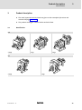
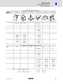
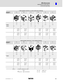
Identification
GST
1−stage
2−stage
3−stage
GFL
2−stage
BA 12.0023−EN
3−stage
7.0
l
15
3
Product description
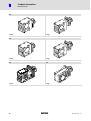
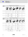
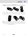
Identification
GKS
3−stage
4−stage
GSS
2−stage
3−stage
GKL
GKR
3−stage
2−stage
16
l
BA 12.0023−EN 7.0
Product description
3
Product features
3.2
Product features
Design
Drive systems have a modular design.
They consist of:
ƒ
Reduction gearboxes
– Helical gearboxes
– Shaft−mounted helical gearboxes
– Helical−worm gearboxes
– Helical−bevel gearboxes
– Bevel gearbox
ƒ
Variable speed drives
ƒ
Motors
Mode of operation
ƒ
Torque and speed conversion
Product family
Pre−stage
1st stage
Helical gearbox
Shaft−mounted helical gearbox
Bevel gearbox
Helical−worm gearbox
ƒ
BA 12.0023−EN
7.0
Helical
Helical
Helical−bevel gearbox
Helical
−−−
Helical
2nd stage
Bevel
Worm
3rd stage
−−−
−−−
Helical
−−−
−−−
The torque reaction must be supported in a suitable manner.
l
17
3
Product description
Product features
Mounting position (A−F) and position of system modules (1−6)
GST
Terminal box, Motec, connector: 2, 3, 4, 5
Without terminal box, Motec, connector: 0
A
B
GFL
D
E
Solid shaft: 6
Hollow shaft: 0
Hollow shaft with shrink disc: 1, 6
Foot: 3, 4
Without foot: 0
Terminal box, Motec, connector: 2, 3, 4, 5
Without terminal box, Motec, connector: 0
A
B
D
E
GKS/GSS/GKL
Solid shaft: 3, 5, 8 (3+5)
Hollow shaft: 0
Hollow shaft with shrink disc: 3, 5
Flange: 3, 5, 8 (3+5)
Without flange: 0
Terminal box, Motec, connector: 2, 3, 4, 5
Without terminal box, Motec, connector: 0
A
B
D
E
GKR
Solid shaft: 3, 5, 8 (3+5)
Hollow shaft: 0
Hollow shaft with shrink disc: 3, 5
Flange: 3, 5, 8 (3+5)
Without flange: 0
Terminal box, Motec, connector: 2, 3, 4, 5
Without terminal box, Motec, connector: 0
A
B
D
E
18
C
C
C
C
l
F
F
F
F
BA 12.0023−EN 7.0
Product description
3
Product features
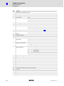
Nameplate
3.2.1
Nameplate
Geared motor
Standard version
Nameplate GNG−001.iso
CSA/UL version
Nameplate GNG−002.iso
BA 12.0023−EN
7.0
l
19
3
Product description
Product features
Nameplate
Pos.
Contents
1
Manufacturer / production location
2
Motor type / standard
3
Gearbox type
4
Motor type
5
Technical data
Ratio
Rated torque
Rated speed
Rated frequency
6
Mounting position / position of the system blocks
7
Lubricant
8
Brake data (if fitted)
Type
AC/DC brake voltage
Braking torque, electrical power input
9
Feedback / pulse encoder or resolver data (if fitted), see product key ^ 23
10
Manufacture data
11
Bar code
12
Rectifier designation
13
Information on operating mode
14
Additional motor
specifications
Order number
Material number; Serial number
Temperature class
Enclosure
Motor protection
15
Valid conformities,
approvals and certificates
CE identification; CCC identification
cURus logo / UL file number
UL energy efficiency logo
16
20
Rated data for
various frequencies
Hz
=
frequency
kW
=
motor power
r/min.
=
motor speed
V
=
motor voltage
A
=
motor current
h
=
Motor efficiency: at a rated power of 100%
cos j
=
motor power factor
17
Application factor (given if < 1.0) / load capacity
18
Year / week of manufacture
19
UL file number
20
Additional customer data
21
Inverter duty motor
22
Motor code for controller parameterisation (code 0086)
23
Efficiency class
24
Maximum ambient temperature
25
Grade A =
26
CC number of the Department of Energy (optional)
27
Ta £ 40°C
28
Partial load efficiencies for 50Hz operation at a rated power of 50% and 75%
29
ALR
30
Weight
voltage tolerance range according to range A according to IEC/EN 60034−1
l
BA 12.0023−EN 7.0
Product description
3
Product features
Examples
Three−phase AC motor with square flange for direct gearbox attachment
Standard version
CSA/UL version
Typenschild−GNG−003.iso/dms
Typenschild−GNG−003.iso/dms
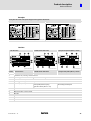
Gearbox
N and W version
M and N version with motor
Typenschild GST−004.iso
Version N and W version
K (compact unit) and D (Disco) − version
Typenschild GST−005.iso
M and N version with motor
Typenschild GKS−006.iso
K (compact unit) and D (Disco) − version
Pos.
1
Production site / country; www.Lenze.com
2
Gearbox type
3
Year of manufacture/ week of manufacture
4
Mounting position / position of the system modules
5
Rated torque/rated speed
6
Lubricant
7
Ratio
8
Material number / serial number
9
Bar code
10
Order number
11
Additional information
12
Additional customer data
BA 12.0023−EN
7.0
Gearbox and motor type
Rated torque
Rated speed/rated frequency
Application factor (data if < 1.0)
l
Operating frequency
Rated torque/rated speed
21
3
Product description
Product features
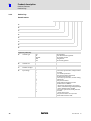
Product key
3.2.2
Product key
Geared motors
LLL
LL
−
L
L
L
L
L
L
0
1
2
3
4
5
6
7
Legend for product key
22
0
Gearbox type
1
Gearbox size
2
Number of stages
3
Input design
GST
GFL
GKS/GKL
GKR
GSS
Helical gearbox
Shaft−mounted helical gearbox
Helical−bevel gearbox
Bevel gearbox
Helical−worm gearbox
A
D
E
G
I
K
M
N
P
Q
R
S
T
U
W
Servo motor, asynchronous, totally enclosed
fan−cooled
Disco variable speed drive
Three−phase AC motor with Motec
SDS three−phase AC motor
Servo motor, asynchronous, internal cooling
Compact unit
Three−phase AC motor
Gearbox with bearing flange for IEC
standard motors or NEMA
DC permanent magnet motor 13.12x/SGS
DC motor, smooth housing, MGFQU/MGFQK
DC motor, ribbed housing, MGFRK
Servo motor, synchronous, totally enclosed
fan−cooled
DC shunt motor 13.5xx
Three−phase AC motor 13.71x/13.75x
Gearbox with free drive shaft
l
BA 12.0023−EN 7.0
Product description
3
Product features
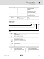
Product key
Legend for product key
4
Output design
G
V
H
S
Solid shaft, smooth (without keyway)
Solid shaft (with keyway)
Hollow shaft
Hollow shaft with shrink disk
5
A
B
C
D
Foot mounting, with centering
Foot mounting, without centering
Without foot, with centering
Without foot, without centering
6
R
K
l
Without flange
With flange (through holes)
With flange (threaded holes)
Motor
Mounting flange/free input shaft
Mech. variable speed drive
071C32
1C
071−1202C
7
Drive size
Examples
Feedback system
LL
Resolver / encoder
L
L
L
0
1
2
3
Legend
0
Type
RS
IG
IK
AS
AM
1
Number
0
1
2, 3, 4...
32, 512,
1024,
2048, ...
2
2−pole resolver for servo motors
2−pole resolver for three−phase AC motors
Number of pole pairs for resolvers
Number of steps / increments per revolution
Voltage
5 V, 9 V,
15 V,
24 V, ...
3
Resolver
Incremental encoder
Incremental encoder with commutation signal
Singleturn absolute value encoder
Multiturn absolute value encoder
Medium supply voltage
Interface or signal level
Standard
T
H
H
E
S
BA 12.0023−EN
7.0
with safety function
TTL
HTL for incremental encoders
Hiperface for absolute value encoders
EnDat
sin/cos 1 Vss
l
U
K
K
F
V
TTL
HTL (for incremental encoders)
Hiperface (for absolute value encoders)
EnDat
sin/cos 1 Vss
23
3
Product description
Transport weights
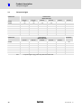
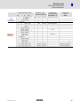
3.3
Transport weights
Geared motors
Motor frame sizes
Gearbox size
063−LL
071−LL
GLL03
< 10
< 10
080−LL
090−LL
GLL04
< 30
GLL05
< 50
GLL06
< 70
< 30
< 40
< 50
< 50
< 60
< 60
< 70
< 70
< 80
< 90
< 100
< 125
GLL07
< 125
< 125
< 150
< 150
< 175
GLL09
< 200
< 200
< 225
< 225
< 250
< 350
< 375
< 375
< 400
< 625
< 650
< 650
GLL11
GLL14
100−LL
Geared motors
Motor frame sizes
Gearbox size
132−LL
160−LL
180−LL
112−LL
Gearboxes
200−LL
225−LL
GLL04
< 30
GLL05
< 50
GLL06
< 150
GLL07
< 200
< 250
GLL09
< 275
< 325
< 475
< 550
GLL11
< 425
< 450
< 600
< 700
< 850
< 400
GLL14
< 700
< 750
< 850
< 950
< 1100
< 625
Tab. 1
24
< 70
< 150
< 250
Transport weights in [kg]; values may differ from table value
l
BA 12.0023−EN 7.0
Technical data
4
General data and operating conditions
4
Technical data
4.1
General data and operating conditions
General data
Conformity and approval
Conformity
2006/95/EC
CE
Low−Voltage Directive
Approvals
M
File No. E210321
CCC
Protection of persons and equipment
Degree of protection
IEC/EN 60034−5
See nameplate
Degrees of protection only apply to horizontal installation
All unused plug−in connections must be sealed with
protective caps or dummy connectors.
Thermal class
F (155 °C)
IEC/EN 60034−1
Permissible voltage
Exceedance of the temperature limit weakens or destroys the
insulation
According to limiting curve A of the pulse voltage from
IEC / TS 60034−25 (image 14)
EMC
IEC/EN 61800−3
Noise emission
Noise immunity
Depending on the controller, see documentation for the
controller.
Operating conditions
Ambient conditions
Climatic
Transport
IEC/EN 60721−3−2
2K3 (−20 ... +70 °C)
Storage
IEC/EN 60721−3−1
1K3 (−20 ... +60 °C)
< 3 months
1K3 (−20 ... +40 °C)
> 3 months
Operation
IEC/EN 60721−3−3
Without brake −15 °C ... +40 °C
Without power reduction
With brake −10 °C ... +40 °C
> +40 °C
With power reduction see,
catalogue
Site altitude
< 1000 m amsl − without power reduction
> 1000 m amsl < 4000m amsl with power reduction, see
catalogue
Humidity
Average relative humidity 85 %, without condensation
Electrical
Motor connection dependent on the
controller
See inverter instructions
Length of motor cable
Length of cable for speed feedback
Mechanical
IEC/EN60721−3−3
BA 12.0023−EN
7.0
3M6
l
25
5
Mechanical installation
Transport equipment for gearbox
5
Mechanical installation
}
Danger!
Only transport the drive with transport equipment or hoists which are suitable
for this load (see transport weights, chapter LEERER MERKER). Ensure a safe
fixing. Avoid shocks!
The motors attached to the gearbox are partially equipped with eyebolts.
These are exclusively determined for motor/gearbox mounting and
dismounting and must not be used for the complete geared motor!
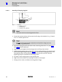
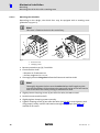
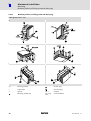
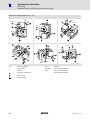
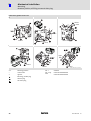
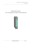
5.1
Transport equipment for gearbox
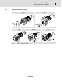
As of size 05, Lenze GST, GKS and GSS gearboxes are as standard available with a transport
thread for eye bolts according to DIN 580. The thread position can be seen from the below
figures. The eye bolts are not contained in the delivery package.
GSTXX−1
Fig. 1
)
GSTXX−2/3
GSSXX−2/3 and GKSXX−3/4
Eye bolt position
Note!
As standard, threads are delivered with plug screws. The plug can be easily
removed, e.g. by using a screwdriver blade. For the thread size and load
carrying capacity of the eye bolt, please see Tab. 2.
26
l
BA 12.0023−EN 7.0
Mechanical installation
5
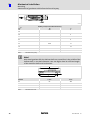
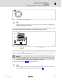
Transport equipment for gearbox
Gearbox size
Thread
max. load carrying capacity of eye bolt to DIN 580
single−strand
two−strand (45°)
45°
GT−GNG−005.iso/dms
05
M8
140
100
06
M8
140
100
07
M12
340
240
09
M16
700
500
11
M20
1200
860
14
M20
1200
860
Tab. 2
}
Load carrying capacity of eye bolt in kg
Danger!
Completely screw in transport aids (such as eye bolts or bearing plates), they
must be flat and applied over their entire surface!
If possible, the transport aids (such as eye bolts or bearing plates) must be
stressed vertically in the direction of the screw axis! Angular tension or tension
to the sides reduces the payload! Observe the information provided in the
DIN 580!
Use additional appropriate lifting aids, if required, to achieve a direction of
loading which is as vertical as possible (highest payload). Secure lifting aids
against shifting!
(
Stop!
Observe load carrying capacity!
Staying under floating load is prohibited!
BA 12.0023−EN
7.0
l
27
5
Mechanical installation
Storage
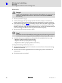
5.2
Storage
If you do not install the gearbox immediately, ensure appropriate conditions of storage.
28
ƒ
Generally
– Store gearbox in dry, clean (dust−free) and sunlight−protected indoor rooms.
– The storage location must be free of vibration and shocks (Veff < 0.2 mm/s) to
avoid roller bearing downtime damage.
– Temperature changes with condensate formation must be avoided.
– Do not activate breather element to prevent air exchange with ambient air.
ƒ
Up to one year:
– Store the gearbox with breather such that the breather screw is located at the top.
– Shafts and bright surfaces are delivered with protection against corrosion. Spots
with defective corrosion protection must be re−treated.
– On motors with condensation drain holes (option), the plug screw must be
removed (see chapter 5.4.1).
ƒ
Over one year, up to two years:
– Before storage, shafts and bright surfaces must be provided with a long−term
anticorrosive agent (e.g. Anticorit BW 366 from the company Fuchs).
– Set up gearbox in mounting position A.
– Fill gearbox with oil grade filled in (see nameplate) up to the top breather / oil
bore. Then mount plug screw or breather element (do not activate) again.
l
BA 12.0023−EN 7.0
Mechanical installation
5
Specified directions of rotation
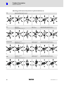
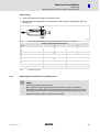
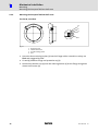
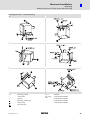
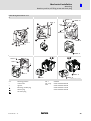
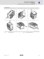
5.3
Specified directions of rotation
GST
GFL
GT−GNG−GST−008.iso/dms
GKR
GKS/GKL
GT−GNG−GKR−006.iso/dms
Fig. 2
BA 12.0023−EN
7.0
GT−GNG−GFL−005.iso/dms
GT−GNG−GKS/GKL−004−iso/dms
GSS
GT−GNG−GSS−007.iso/dms
Direction of rotation of drive
l
29
5
Mechanical installation
Mounting
Preparation
5.4
Mounting
5.4.1
Preparation
(
Stop!
Thoroughly remove anticorrosion agents from output shafts and flange faces.
Correcting the oil quantity
If the oil quantity has been increased in the gearbox for long−term storage (see chapter
5.2), the oil must be completely drained and then filled in again for the corresponding
mounting position. The following steps must be observed:
1. Place receptacle under oil drain plug.
2. Remove ventilation / oil filler plug.
3. Completely drain lubricant.
4. Screw in oil drain plug.
5. Fill in oil quantity for the corresponding mounting position (^ 66).
6. Screw in ventilation / oil filler plug.
Condensation drain hole
)
Note!
Lenze delivers motors with condensation drain holes with sealed condensation
drain holes. The holes are sealed with a plastic plug or a plug screw. This does
not impair the enclosure and the motor is protected against ingress of foreign
particles during transport and operation. For further information, please see
chapter 8.2.1.
30
l
BA 12.0023−EN 7.0
Mechanical installation
5
Mounting
General information about the assembly of drive systems
5.4.2
General information about the assembly of drive systems
(
Stop!
The lubricant fill quantity of the gearboxes is matched to the mounting
position. The mounting position indicated on the nameplate must be observed
to avoid damage to the gearbox.
5.4.3
ƒ
Take safety measures prior to any operation:
– Disconnect the machine from the mains, ensure standstill of the drive system and
avoid any machine movement.
– Check the proper state of the drive system. Never install and set up damaged drive
systems.
– Check the combination of drive function and machine functions. Check the
direction of rotation (see 5.3).
ƒ
The mounting surfaces must be even, without torsion, and free from vibration.
ƒ
Align the drive system on the mounting surfaces exactly with the machine shaft to
be driven.
– Ensure that the assembly is without torsion to avoid additional load.
– Compensate for minor misalignments by using suitable flexible couplings.
ƒ
Support the reaction torque appropriately.
ƒ
Fixings of accessories and attachments must be secured against loosening.
We recommend that screw connections are glued.
Assembly of transmission elements on solid shafts
ƒ
Draw the transmission elements onto the output shaft only by using the centering
thread.
(
Stop!
Shocks and blows to the shafts damage the roller bearings.
BA 12.0023−EN
7.0
l
31
5
Mechanical installation
Mounting
Attachment of motors to gearboxes with bearing housing
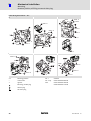
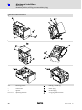
5.4.4
Attachment of motors to gearboxes with bearing housing (input design N)
1
2
0
1
K12.0621
Fig. 3
Input side design N
0
1
Drive size
Motor shaft
Spider / gear rim
Coupling hub
Assembly
dimension
Standard hub
Locking screw
max. l
M
Thread
Thread
[ mm ]
M4
[ mm ]
[ mm ]
[ mm ]
11
23
23
1B
14
30
30
2B
11
23
23
1C
19
40
25
2C
14
40
25
3C
14
40
25
4C
14
40
25
6C
11
40
25
7C
19
40
25
1D
24
50
50
2D
19
40−50
50
1E
28
30−60
30
2E
24
30−60
30
3E
19
30−60
30
4E
24
50
50
1F
28
30−60
30
2F
24
30−60
30
3F
24
50
50
1G
38
80
80
2G
28
60
60
3G
38
80
80
1H
42
110
110
2h
48
110
110
3H
38
80
80
1K
55
110
110
2K
60
140
140
Tab. 3
Locking screw
Keyway
Clamping hub
D
1A
32
1
2
Key 1)
Clamping ring hub
DIN
6885/1
[ mm ]
Thread
[ mm ]
Tightening
torque
[ Nm ]
[ mm ]
Tightening
torque
[ Nm ]
M3
1.34
*
M3
1.34
M4
2.9
B6 x 6 x 16
M5
M6
10.5
−−−
M4
B5 x 5 x 16
*
−−−
−−−
B6 x 6 x 16
M4
2.9
2.9
*
−−−
−−−
M4
2.9
M5
6
−−−
−−−
M8
35
−−−
−−−
B8 x 7 x 18
M5
B6 x 6 x 18
M6
10.5
*
B8 x 7 x 18
M6
M8
M8
M10
25
69
*
*
Attachment of motors to gearboxes with mounting flange
* Use original key for the motor
1) Key for standard hub and clamping hub
l
BA 12.0023−EN 7.0
Mechanical installation
5
Mounting
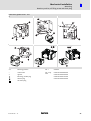
Coupling hubs
5.4.5
Coupling hubs
General
)
Note!
Standard hubs, clamping hubs and clamping ring hubs are
maintenance−free.We recommend checking the star−shaped spider and
system components when inspecting the drive.
5.4.5.1
Assembly of standard hub / clamping hub
1. Fit motor key (2).
– Fit enclosed key for drive sizes LC, LE, LF.
2. Push the coupling hub over the motor shaft, mounting dimension m (see Fig. 3 and
Tab. 3) must be observed.
3. Secure coupling hub against axial movement using the fixing screw or clamping
screw (1).
4. Lay spider in the coupling claw on the gearbox side.
5. Align claws of the motor−side coupling hub with its counterpart.
6. Slowly push on motor, and bolt on to the gearbox flange.
BA 12.0023−EN
7.0
l
33
5
Mechanical installation
Mounting
Coupling hubs
5.4.5.2
Assembly of clamping ring hub
1
3
2
Fig. 4
Coupling
1
2
3
)
Clamping ring hub
Clamping ring
Clamping screws (DIN912)
Note!
The motor shaft must be designed with fit k6.
1. Grease the contact surfaces of the motor shaft using a thin−bodied oil, e. g. Castrol
4 in 1" or Klüber Quitsch Ex"!
(
Stop!
Do not use oil or grease with molybdenum−disulphide or high−pressure
additives, or grease pastes!
2. Push the coupling hub over the motor shaft, mounting dimension m" (see Fig. 3
and Tab. 3) must be observed.
3. Align the hub and tighten the clamping screws until they have contact.
4. Tighten the clamping screws evenly and crosswise with gradually rising torque until
the indicated tightening torque (see Tab. 3) is reached at all clamping screws. In the
intermediate steps, this procedure should also be repeated until the indicated
tightening torque is reached at all clamping screws.
5. Lay spider in the coupling claw on the gearbox side.
6. Align claws of the motor−side coupling hub with its counterpart.
7. Slowly push on motor, and bolt on to the gearbox flange.
34
l
BA 12.0023−EN 7.0
Mechanical installation
5
Mounting
Attachment of gearboxes with hollow shafts and keyway
5.4.5.3
Disassembly of clamping ring hub
1. Loosen the clamping screws evenly one after the other.
(
Stop!
Each screw must only be loosened by half a revolution per pass! Unscrew all
clamping screws by 3 − 4 threads.
2. Remove the screws next to the forcing threads and screw them into the other
threads until they have contact.
3. Tighten the screws in the forcing threads crosswise and step−by−step so that the
clamping ring is loosened.
4. Clean and grease all contact surfaces including threads and head of the clamping
screws before reassembly.
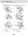
5.4.6
Attachment of gearboxes with hollow shafts and keyway
Mounting
1. Draw the gearbox with hollow shaft onto the machine shaft to be driven:
– Apply the supplied assembly paste (Fig. 5) on the shaft and in the hollow shaft
bore.
GT−GNG−GKR−011.iso
Fig. 5
(
GT−GNG−GKR−011_a.iso
Application of assembly paste against fretting corrosion (included in the scope of supply)
Stop!
Take up forces only via the hollow shaft, and not via gearbox housing.
2. Secure the gearbox axially:
– The hollow shaft has snap ring grooves for axial securing. Parts used to fix the
shaft are not included in the scope of supply.
BA 12.0023−EN
7.0
l
35
5
Mechanical installation
Mounting
Attachment of gearboxes with hollow shafts and keyway
K12.0611
Auxiliary tool (recommended dimensions)
Æ dH7
d2
c7
18
20
M6
4
25
30
M10
5
6
35
M12
7
40
45
M16
8
9
50
55
M16
M20
10
11
60
70
M20
13
14
80
M20
16
100
M24
24
Tab. 4
)
Dimensions in [mm]
Note!
With bevel gearbox GKR, the hollow shafts are turned free in the middle of the
hollow shaft, i.e. the bore diameter is 0.1 mm higher here! A sufficient length
of the machine shaft must be observed.
GKR size
l1 min
l max.
03
85
100
04
105
120
05
127
143
06
150
170
Tab. 5
36
Dimensions in mm
l
BA 12.0023−EN 7.0
Mechanical installation
5
Mounting
Mounting the shrink disc with a rotating cover
Dismounting
1. Undo axial gearbox locking in the hollow shaft.
2. Remove/extract the gearbox from the motor shaft using an appropriate auxiliary
tool (Fig. 6).
K12.0611
Fig. 6
Dismantling of gearboxes with hollow shaft using the auxiliary tool, not for GKR
Auxiliary tool (recommended dimensions)
Æ dH7
c8
c9
25
30
10
3
35
12
3
40
45
16
4
50
55
16
20
5
60
70
20
5
80
20
6
100
24
8
Tab. 6
5.4.7
Dimensions in [mm]
Mounting the shrink disc with a rotating cover
(
Stop!
Do not dismantle new shrink disc.
Never tighten clamping screws before the machine shaft is pushed in.
Otherwise the hollow shaft may be deformed plastically. Protect the shrink
disc against contact while in operation by appropriate measures (e.g. cover).
Degrease hollow shaft bore and machine shaft!
BA 12.0023−EN
7.0
l
37
5
Mechanical installation
Mounting
Mounting the shrink disc with a rotating cover
5.4.7.1
Mounting the shrink disc
Depending on the design, the shrink discs may be equipped with a rotating cover
(protective cap, pos. 1).
)
Note!
This cover is fitted to the shrink disc on delivery.
2
1
5.
1.
1
2
KL_GFL06_001−dms
Fig. 7
1
2
Protection cover
Clamping screws
1. Remove protective cap (1), if available.
2. Check machine shaft
– Diameter in fit tolerance h6
– Surface roughness Rz £ 15 mm
3. Thoroughly clean and degrease hollow shaft bore and machine shaft.
)
Note!
Thoroughly degrease the bore over the entire hollow shaft length to make
sure that remainders of the anticorrosion agent will not be carried off into the
area of the shrink disc when pushing on the machine shaft.
4. Slightly loosen clamping screws (2) one after the other, do not unscrew!
5. Push drive onto machine shaft.
6. Slightly tighten clamping screws manually.
7. Tighten clamping screws (2) one after the other (see Fig. 8) in several passes, with
rising torque, evenly until the indicated screw−tightening torque (see Tab. 7 ) is
reached at all screws.
38
l
BA 12.0023−EN 7.0
Mechanical installation
5
Mounting
Mounting the shrink disc with a rotating cover
GT−GNG−003.iso/dms
Fig. 8
I
Explanation: "one after the other"
Tip!
Several (in general more than 5 ) passes are necessary until the full tightening
torque is reached at all screws!
The shrink disc is mounted correctly and fixed when the faces of the outer ring and the
inner ring are aligned (Fig. 9). Minimum misalignments are permissible.
GT−GNG−001.iso
Fig. 9
Hollow shaft with shrink disk
3
4
0
Outer ring
Inner ring
free of grease
Hollow shaft bore [mm]
20
25
30
35
40
50
60
65
80
100
Torque [ Nm ]
12
30
30
30
30
30
59
70
59
100
Tab. 7
)
Tightening torque for the clamping screws
Note!
If a different tightening torque is indicated on the shrink disc, this tightening
torque has priority over the value indicated in the table.
8. Push protective cap (1, Fig. 7) onto the shrink disc.
I
Tip!
For finding out the cause of non−reached torques of the shrink disc connection,
please go through the troubleshooting list in chapter 9.
BA 12.0023−EN
7.0
l
39
5
Mechanical installation
Mounting
Mounting the shrink disc with a rotating cover
Dismounting
}
Danger!
Loose drive components or drive components falling down may cause injury to
persons or damage to the machine. Secure the drive components before
disassembly.
1. Remove protective cap (1).
2. Loosen clamping screws (2) evenly one after the other each by ¼ revolution in
several passes. Do not unscrew clamping screws completely to prevent accidents!
3. Press off outer ring (see Fig. 9), if necessary. For this, loosen the outer ring using the
forcing threads and some clamping screws (number corresponding to the forcing
threads in the inner ring). For loosening the outer ring, screw in the screws evenly to
prevent canting. Press off the outer ring until loosened completely.
4. Remove the drive from the machine shaft.
(
Stop!
Dismantle the shrink disc only for cleaning purposes. Afterwards, grease bevel
surfaces and screws using a solid lubricant with a friction factor of m = 0.04.
ƒ
Suitable lubricants on molybdenum−disulphide lubricant (MoS2) basis are, e.g.:
– Molykote G Rapid (company Dow Corning)
– Molykote BR2 Plus (company Dow Corning)
– Molykombin UMFT1 (company Klüber Lubrication)
Usually, disassembly problems only occur if:
40
ƒ
the connection is spinning due to overload or a too low friction factor and fretting
corrosion has occurred,
ƒ
the shrink disc has been tightened too much leading to a plastic deformation of
components,
ƒ
the components are corroded.
l
BA 12.0023−EN 7.0
Mechanical installation
5
Mounting
Mounting the fixed cover
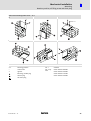
5.4.8
Mounting the fixed cover
for size 09, 11 and 14
)
Note!
This cover is supplied loose on delivery!
3x120°
x
x
1
3
2
Fig. 10
1
2
3
Protection cover
Cheese head screw
Thread reducing sleeve
1. Screw the three reducing bushes (3) into the flange with a screwdriver so they are
flush and staggered by 120°.
2. Fasten the protective cap (1) over the reducing bushes (3) on the flange using three
cheese head screws (2).
BA 12.0023−EN
7.0
l
41
5
Mechanical installation
Mounting
Mounting the hoseproof hollow shaft cover
5.4.9
Mounting the hoseproof hollow shaft cover
for size 09, 11 and 14
3x120°
4
1
3
2
Fig. 11
1
2
3
4
Protection cover
Cheese head screw
Thread reducing sleeve
Seal
1. Screw the three reducing bushes (3) into the flange with a screwdriver so they are
flush and staggered by 120°.
2. Fit seal (4) between flange and protective cap (1).
3. Fasten the protective cap (1) over the reducing bushes (3) on the flange using three
cheese head screws (2).
42
l
BA 12.0023−EN 7.0
Mechanical installation
5
Mounting
Gearboxes with breathers
5.4.10
Gearboxes with breathers
(
Stop!
Do not place gearbox onto breather valve!
When using gearbox sizes 03, 04 and 05 (except for GSS 05) it is not necessary to provide
special breathing measures.
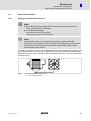
Breather elements are mounted for gearbox sizes 06 to 14 and GSS 05. In special cases, they
may be done without. When using gearbox sizes 09 to 14 in mounting position C, we
recommend the use of an oil compensation container (chapter 5.4.12).
Gearboxes supplied with a breather element bear a corresponding label on the gearbox.
Remove shipping bracket on breather valve.
GT−GNG−13285760.iso/dms
For mounting positions differing from the standard mounting positions A − F, the breather
function must be checked. Mount breather elements supplied loose (differing from the
standard) as described in chapter 5.4.11. Gearboxes which can be mounted in different
positions (see chapter 8.2.6) are supplied without breather element.
Ensure ventilation before initial commissioning!
(
Stop!
ƒ Rotate gearbox to the mounting position shown on the nameplate (see
nameplate, page 19− 21 and chapter 5.4.11).
ƒ With gearbox types GSTLL−3, GFLLL−3, GSSLL−3 and GKSLL−4, the
pre−stage is separately ventilated! (Exception: size 06)
BA 12.0023−EN
7.0
l
43
5
Mechanical installation
Mounting
Breather position, oil filling screw and drain plug
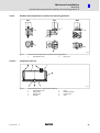
5.4.11
Breather position, oil filling screw and drain plug
Helical gearbox GST 05 ... 09−1
A
B
C
D
E
F
GT−GNG−GST−1−001_A−F.iso/dms
A...F
Mounting positions
*
on both sides
**
opposite
Pos. 1
Standard
Breathing / oil filler plug
Pos. 2 only
with:
GST05−1A 080C22
44
Oil drain plug
Oil−control plug
l
BA 12.0023−EN 7.0
Mechanical installation
5
Mounting
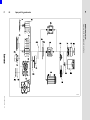
Breather position, oil filling screw and drain plug
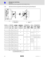
Helical gearbox GST 05 ... 14−2, foot mounting
A
B
C
D
E
F
GT−GNG−GST−2−001_A−F.iso/dms
A...F
Mounting positions
Pos. 1
Standard
*
**
on both sides
Pos. 2 only
with:
GST05−2M VLL 090CLL
opposite
GST05−2M VLL 100CLL
Breathing / oil filler plug
GST06−2M VLL 112CLL
Oil drain plug
GST07−2M VLL 160CLL
Oil−control plug
BA 12.0023−EN
7.0
l
45
5
Mechanical installation
Mounting
Breather position, oil filling screw and drain plug
Helical gearbox GST 06...14−3
A
B
C
D
E
F
GT−GNG−GST−3−001_A−F.iso/dms
A...F
Mounting positions
*
on both sides
Pos. 1
Standard
**
opposite
Pos. 2 only
with:
GST05−3M VLL 090CLL
Breathing / oil filler plug
Oil−control plug
Oil drain plug
46
GST05−3M VLL 100CLL
GST06−3M VLL 112CLL
l
BA 12.0023−EN 7.0
Mechanical installation
5
Mounting
Breather position, oil filling screw and drain plug
Shaft−mounted helical gearbox GFL 05 ... 14−2
A
B
C
1
2
1
2
GFL09...14
1
2
D
E
F
1
2
2
1
2
1
GT−GNG−GFL−2−001.iso/dms
A...F
Mounting positions
Pos. 1
Standard
*
**
on both sides
Pos. 2 only
with:
GFL05−2M LLL 090CLL
opposite
GFL05−2M LLL 100CLL
Breathing / oil filler plug
GFL06−2M LLL 112CLL
Oil drain plug
GFL07−2M LLL 160CLL
Oil−control plug
BA 12.0023−EN
7.0
l
47
5
Mechanical installation
Mounting
Breather position, oil filling screw and drain plug
Shaft−mounted helical gearbox GFL 06 ... 14−3
A
B
C
2
1
GFL06...14
2
1
GFL14
GFL06...14
*
GFL05
GFL05
GFL05
1
2
D
E
F
GFL06...14
GFL05
*
1
2
2
*
GFL05
1
GFL06...14
1
*
2
GFL05
GFL06...14
GT−GNG−GFL−3−001.iso/dms
A...F
Mounting positions
Pos. 1
Standard
*
**
on both sides
Pos. 2 only
with:
GFL07−3M LLL 090CLL
opposite
GFL07−3M LLL 100CLL
GFL09−3M LLL 112CLL
Breathing / oil filler plug
Oil drain plug
Oil−control plug
48
l
BA 12.0023−EN 7.0
Mechanical installation
5
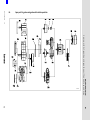
Mounting
Breather position, oil filling screw and drain plug
Helical bevel gearbox GKS 05...14−3
A
B
C
1
2
*
GKS09...14
1
GKS09...14
* GKS05...07
2
* GKS09...14
GKS05...07
* GKS05...07
1
2
* GKS09...14
GKS09...14
D
E
F
**
GKS05...07
**
GKS09...14
2
GKS09...14
GKS09...14
1
GKS05...07
GKS09...14
GKS05...07
GKS05...07
GT−GNG−GKS−3−001_A−F.iso/dms
A...F
Mounting positions
Pos. 1
Standard
*
**
on both sides
Pos. 2 only
with:
GKS05−3M LLL 090CLL
opposite
GKS05−3M LLL 100CLL
Breathing / oil filler plug
GKS06−3M LLL 112CLL
Oil drain plug
GKS07−3M LLL 160CLL
Oil−control plug
BA 12.0023−EN
7.0
l
49
5
Mechanical installation
Mounting
Breather position, oil filling screw and drain plug
Helical bevel gearbox GKS 05 ... 14−4
A
B
C
* GKS06...14
GKS14
1
** GKS05
2
GKS05...07
* GKS05...07
GKS09...14
*
2
* GKS09...14
1
**
GKS05
*
GKS06...14
1
2
*
GKS06...14
GKS05...07
* GKS05...07
* GKS09...14
** GKS05
GKS09...14
D
E
F
GKS05...07
**
GKS09...14
GKS09...14
GKS05...07
GKS05
GKS05...07
**
**
GKS05
GKS05...07
1
* GKS06...14
1
2
2
1
GKS09...14
GKS09...14
**
GKS05
2
GKS06...14
GKS06...14
GT−GNG−GKS−4−001_A−F.iso/dms
A...F
Mounting positions
Pos. 1
Standard
*
**
on both sides
Pos. 2 only
with:
GKS07−4M LLL 090CLL
opposite
GKS07−4M LLL 100CLL
GKS09−4M LLL 112CLL
Breathing / oil filler plug
Oil drain plug
Oil−control plug
50
l
BA 12.0023−EN 7.0
Mechanical installation
5
Mounting
Breather position, oil filling screw and drain plug
Helical−worm gearbox GSS 05 ... 07−2
A
B
C
*
1
*
2
1
*
2
D
E
F
**
**
2
1
GT−GNG−GSS−2−001_A−F.iso/dms
A...F
Mounting positions
Pos. 1
Standard
*
**
on both sides
Pos. 2 only
with:
GSS05−2M LLL 090CLL
opposite
GSS05−2M LLL 100CLL
Breathing / oil filler plug
GSS06−2M LLL 112CLL
Oil drain plug
GSS07−2M LLL 160CLL
Oil−control plug
BA 12.0023−EN
7.0
l
51
5
Mechanical installation
Mounting
Breather position, oil filling screw and drain plug
Helical−worm gearbox GSS 05...07−3
A
B
C
* GSS06/07
1
** GSS05
2
*
2
1
**
GSS05
*
*
GSS06/07
1
2
*
GSS06/07
** GSS05
D
E
F
**
GSS05
**
**
GSS05
1
* GSS06/07
1
2
2
1
**
GSS05
GSS06/07
2
GSS06/07
GT−GNG−GSS−3−001_A−F.iso/dms
A...F
Mounting positions
Pos. 1
Standard
*
**
on both sides
Pos. 2 only
with:
GSS07−3M LLL 090CLL
opposite
GSS07−3M LLL 100CLL
Breathing / oil filler plug
Oil drain plug
Oil−control plug
52
l
BA 12.0023−EN 7.0
Mechanical installation
5
Mounting
Breather position, oil filling screw and drain plug
Bevel gearbox GKR
A
B
C
D
E
F
GT−GNG−GKR−2−001_A−F.iso/dms
A...F
BA 12.0023−EN
Mounting positions
7.0
Breathing / oil filler plug
l
53
5
Mechanical installation
Mounting
Breather position, oil filling screw and drain plug
Helical−bevel gearbox GKL 07...09−3
A
B
C
D
E
F
GT−GNG−GKL−001.iso/dms
A...F
Mounting positions
Breathing / oil filler plug
*
on both sides
Oil drain plug
**
opposite
Oil−control plug
Pos. 1 or 2
depending on version
Sealing plug without function
54
l
BA 12.0023−EN 7.0
Mechanical installation
5
Mounting
Gearbox with compensation container for mounting position C
5.4.12
Gearbox with compensation container for mounting position C
GST
GKS
GFL
K12.0956
Fig. 12
Position of the compensation container in mounting position C
1
5.4.12.1
Intermediate cover
9
Plug screw
Component parts list
K12.0956
Fig. 13
Component−parts list − compensation container
1
2
3
4
BA 12.0023−EN
7.0
Intermediate cover
Fixing screw
Sealing rings
Housing
5
6
7
8
l
Cover
Breather element
Hexagon nut
Seal
55
5
Mechanical installation
Mounting
Gearbox with compensation container for mounting position C
Mounting
1. Mount gearbox in mounting position C (motor on top).
2. Remove the plug (9) from the intermediate cover (1).
3. Mount housing (4) using seal (3) and fixing screw (2) to intermediate cover (1)
(instead of the plug (9)).
4. Use hexagon nut (7) to bolt the breather element (6) to the cover (5).
5. Mount cover (5) and seal (8) to the housing (4).
(
Stop!
For transport the compensation reservoir must be removed and the plug must
seal the gearbox (pos. 9).
56
l
BA 12.0023−EN 7.0
Electrical installation
6
Motor connection
6
Electrical installation
{
Danger!
Electrical connections must only be carried out by skilled personnel!
6.1
Motor connection
To correctly connect the motor, please observe:
6.2
ƒ
the notes in the terminal box of the motor
ƒ
the notes in the Operating Instructions of the motor
ƒ
the technical data on the motor nameplate.
Motor options
To correctly connect the motor options, e. g. brakes or feedback systems, please observe:
BA 12.0023−EN
ƒ
the notes in the corresponding terminal box
ƒ
the notes in the corresponding operating instructions
ƒ
the technical data on the corresponding motor nameplate.
7.0
l
57
7
Commissioning and operation
Before switching on
7
Commissioning and operation
(
Stop!
The drive may only be commissioned by skilled personnel!
7.1
Before switching on
Please check:
7.2
ƒ
Does the drive appear undamaged?
ƒ
Is the mechanical fixing o.k.?
ƒ
Has the electrical connection been carried out properly?
ƒ
Are all rotating parts and surfaces that may become hot protected against contact?
ƒ
If the oil level of the drive has been increased due to storage purposes (¶ 28), it
must be reduced again to the height permissible for the intended mounting
position.
ƒ
For gearboxes with breathing:
– Has the transport locking device been removed?
ƒ
For gearboxes with backstop:
– Will the motor start to rotate in the correct direction? (¶ 29)
During operation
)
Note!
The helical−worm gearboxes reach their full performance only after a short
running−in period of 24...48 hours at rated torque!
During operation, check the drive periodically and take special care of:
58
ƒ
Deviations from normal operation such as
– abnormal noises, stronger vibrations, or increased temperatures
– leakages,
– loose fixing elements,
– the condition of the electrical cables.
ƒ
If any interference should occur, you have to stop the drive and go through the steps
for troubleshooting and fault elimination (chapter 9). If the interference cannot be
eliminated, please contact the Lenze Service.
l
BA 12.0023−EN 7.0
Maintenance
8
Maintenance intervals
8
Maintenance
Lenze gearboxes and geared motors are filled with a drive and design−specific lubricant
filling upon delivery. This original filling corresponds to the lubricant listed in the column
of the respective gearbox type from Lenze. The important factors for the lubricant filling
on ordering are the mounting position and the design.
)
Note!
Gearboxes of size 03 and 04 are lubricated for life. Because of the minimum
thermal load it is not necessary to replace the lubricant.
8.1
Maintenance intervals
ƒ
The mechanical power transmission system is free of maintenance.
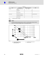
ƒ
Gearboxes as of size 05 (pre−stages as of size 06) require regular lubricant
replacement.
– The type of lubricant is indicated on the nameplate. Replace the lubricant only
with the same type.
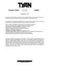
– The lubricant maintenance interval depends on the oil temperature, see Fig. 14.
ƒ
Shaft seals and roller bearings:
– The service life depends on the operating conditions.
– Replace seals in case of leakage to avoid consequential damage.
)
Note!
When changing the lubricant, Lenze recommends also changing the grease
packing of the bearings and replacing the rotary shaft seals!
(
Stop!
For drive systems: Also observe the maintenance intervals for the other drive
components!
BA 12.0023−EN
7.0
l
59
8
Maintenance
Maintenance intervals
Lubricants
Type
Specification
Ambient temperature
Note
CLP 460
Oil on mineral basis with
additives
CLP PG 460
Oil on synthetic basis
(polyglycol)
−20 °C ... + 40 °C
Do not mix with mineral
oil!
CLP HC 220 USDA H1
Food−compatible oil on
synthetic basis
−20 °C ... + 40 °C
Approval acc. to USDA−H1
CLP HC 320
CLP HC 220
Oil on synthetic basis
(synthetic hydrocarbon)
−25 °C ... + 50 °C
Can be mixed with
residual mineral oil
CLP HC 46
Oil on synthetic basis
(synthetic hydrocarbon)
−40 °C...0 °C
Good cold−flow behaviour
CLP PG 220 USDA H1
Food−compatible oil on
synthetic basis
20 °C ... + 40 °C
Approval acc. to USDA−H1
Tab. 8
)
0 °C ... + 40 °C
Overview of lubricant change
Note!
In case of ambient temperatures <−20°C or >+40°C, please contact Lenze!
Observe increased starting torques at low temperatures!
GT−GNG−002.iso/dms
Fig. 14
0
1
60
Oil sump temperature [°C]
Oil life/changing intervals
[operating hours h]
l
2
3
Synthetic oil CLP HC/CLP PG
Mineral oil CLP
BA 12.0023−EN 7.0
Maintenance
8
Maintenance operations
Opening the condensation drain hole
8.2
Maintenance operations
8.2.1
Opening the condensation drain hole
)
Note!
ƒ Depending on the mounting position, the condensation drain holes are
always at the bottom of the motor!
ƒ For condensate drainage
– the motor must be deenergised;
– the plugs (screws) must be removed.
(
Stop!
To restore the enclosure, re−insert the plugs (screws) after condensate
drainage. If the condensation drain holes are not sealed again, the IP enclosure
of the motor will be reduced. For horinzontal motor shafts to IP23 and for
vertical motor shafts to IP20.
The required maintenance intervals strongly depend on the corresponding ambient and
operating conditions. Initially, the condensation drain holes should be opened more
frequently (at least once a week) to obtain experimental values for the condensate
quantity arising.
0
Fig. 15
Motor with condensation drain holes
0
BA 12.0023−EN
7.0
Condensation drain holes
l
61
8
Maintenance
Maintenance operations
Lubricate roller bearings
8.2.2
Lubricate roller bearings
The roller bearings on motors and gearboxes from Lenze are filled with the greases listed
below:
Ambient temperature
Manufacturer
Type
−30...+50°C
−30...+80°C
−40...+60°C
Fuchs
Klüber
Klüber
Renolit H 443
Petamo 133 N
Microlube GHY 72
−30...+80°C
−15...+60°C
Klüber
Klüber
Petamo GHY 133 N
Klüberplex BE 11−462
−30 °C ... +70 °C
−40 °C ... +80 °C
Lubcon
Klüber
Thermoplex 2TML
Asonic GHY 72
Gearbox roller bearing
GST, GFL, GKS, GKR, GKL
Gearbox roller bearing
GSS
Motor roller bearing
Special grease for gearbox roller bearing
Low−temperature oils,
observe critical starting
performance at low
temperatures
−40...+80°C
Klüber
Asonic GHY 72
Biodegradable oil
(lubricant for forestry,
agriculture and water
economy)
−40...+50°C
Fuchs
Plantogel 0120S
The following lubricant quantities are required:
62
ƒ
For fast−running bearings (motor and drive end of gearbox): fill approx. one−third of
the hollow space between rolling bodies with grease.
ƒ
For slow−running bearings (in gearbox and driven side of gearbox): fill approx.
two−thirds of the hollow space between roller bearings with grease.
l
BA 12.0023−EN 7.0
Maintenance
8
Maintenance operations
Table of lubricants
8.2.3
Table of lubricants
)
Note!
Please note that the recommendation of a lubricant/grease or its listing in a
Lenze lubricant table does not mean that Lenze is liable for these lubricants or
damages resulting from incompatibilities of materials used.
The lubricants listed in the lubricant table are permissible for Lenze drives. Specialty
lubricants must be used, for example, for long−term storage or special operating
conditions. These corresponding lubricants are available at a surcharge.
Observe the following legend of the lubricant table for the selection of lubricants!
BA 12.0023−EN
7.0
CLP
Þ
Mineral oil
CLP PG
Þ
Polyglycol oil
CLP PAO
Þ
Synthetic hydrocarbon or poly−alpha−olefin oil
CLP E
Þ
Diester oil (water pollution class 1)
1)
Þ
No test results are currently available about the performance of listed lubricants for
worm gearbox lubrication. If these oils are used, the permissible torque must be reduced
to 80% of the catalogue values.
2)
Þ
Polyglycol oils cannot be mixed with other oil types
3)
Þ
For ambient temperatures higher than 40°C please contact the manufacturer for exact
ambient conditions!
4)
Þ
Observe critical starting behaviour for low temperatures! For temperatures lower than
−25°C special measures for the motor storage and NBR shaft seals are necessary!
5)
Þ
Ambient temperature range
ä
`
Þ
Food−grade lubricant
Þ
Biodegradable lubricant (lubricant for forestry, agriculture and water supply and
distribution)
d
Þ
Low−temperature oils, observe critical starting performance at low temperatures!
l
63
8
Maintenance
Maintenance operations
Table of lubricants
Ambient temperature [°C]
−50
0
+50
0
DIN 51517−3: CLP
ISO 12925−1: CKC/CKD
+40
Gearbox type
GKL, GST, GFL, GKS,
GKR, GKK04 ... 06
Omala 460
as of 2011 Omala
S2 G 460
Omala HD 320
as of 2011 Omala
S4 GX 320
CLP
VG 460
+50 3)
CLP HC
VG 320
−20
+40
CLP PG
VG 220
−20
+40
CLP PG
VG 460
−20
+50 3)
CLP E
VG 320
CLP
VG 460
+50 3)
CLP HC
VG 320
+40
+40
CLP PG
CLP PG
VG 460
VG 220
Klübersynth GH 6−460 2)
Klübersynth GH 6−220 2)
Klübersynth GH 6−32 1) 2)
−25
Shell
0
−20
−20
−30
−40
`
+40
−25
0 4)
d
CLP PG
VG 32
0 4)
d
CLP HC
VG 46
Naturelle Gear Fluid
EP 320
Tivela S 220
as of 2011 Omala S4 WE
220
Tivela S 460
as of 2011 Omala S4 WE
460
Naturelle Gear Fluid
EP 320 1)
Klüberoil
GEM 1−460 N
Klübersynth
GEM 4−320 N
Klüber Summit
HySyn FG−46
Klübersynth GEM
4−46 N
Klüberoil
4 UH1−220N
Klübersynth
GEM 2−320
Renolin CLP 460
Renolin Unisyn
CLP 320
−20
+40
ä
CLP HC
VG 220
−20
+50 3)
`
CLP E
VG 320
CLP
VG 460
+50 3)
CLP HC
VG 320
−20
+40
CLP PG
VG 460
−20
+40
CLP E
VG 320
Plantogear 320 S
CLP
CLP HC
CLP PG
CLP
CLP HC
CLP PG
CLP PG
VG 460
VG 320
VG 460
VG 460
VG 320
VG 220
VG 460
AGIP BLASIA 460
AGIP BLASIA SX 320
CLP
VG 460
CLP HC
VG 320
CLP HC
VG 460
Mobil SHC Cibus 460
CLP HC
VG 220
Mobil SHC Cibus 220
CLP PG
VG 220
Mobil Glygoyle 220 1) 2)
CLP PG
VG 460
Mobil Glygoyle 460 1) 2)
CLP
VG 460
Carter EP 460
CLP HC
VG 320
Carter SH 320
0
−25
0
−25
−20
0
−25
−20
−20
0
+40
+40
+50 3)
+40
+40
+50 3)
+40
+40
+40
−10
+50
−10
+40
−20
+40
−20
+40
0
−25
`
+50 3)
−25
64
Gearbox type
GSS
GKK07
+40
+50 3)
ä
ä
ä
ä
l
Klübersynth GEM 2−320 1)
Renolin PG 460 1) 2)
Plantogear 320 1)
AGIP BLASIA S 460 1) 2)
Energol GR−XP 460
Enersyn EP−XF 320
Enersyn SG−XP 220 1) 2)
Enersyn SG−XP 460 1) 2)
Mobilgear 600 XP
460
Mobilgear SHC Gear
320
BA 12.0023−EN 7.0
Maintenance
8
Maintenance operations
Table of lubricants
Ambient temperature [°C]
−50
0
+50
+50 3)
−10
−20
+40
0 4)
−40
ä
ä
d
CLP HC
VG 460
Cassida Fluid GL 460
CLP PG
VG 220
Cassida Fluid GL 220
CLP HC
VG 46
Cassida HF 46
−25
CLP
CLP
CLP
CLP HC
VG 460
VG 460
VG 460
VG 320
−25
+50 3)
CLP HC
VG 320
−25
+50 3)
CLP HC
VG 320
Alpha SP 460
Optigear BM 460
Tribol 1100/460
Alphasyn EP 320
Optigear Synthetic
A 320
Tribol 1510/320
Tribol Bio Top
1418/320
−20
+40
`
CLP E
VG 320
d
ä
ä
CLP HC
VG 46
+50 3)
CLP HC
VG 320
Optileb GT 220
CLP
VG 220
Food Proof 1810/220
CLP PG
CLP PG
CLP PG
CLP PG
VG 220
VG 460
VG 220
VG 460
0 4)
−40
−25
7.0
ISO 12925−1: CKC/CKD
Gearbox type
GKL, GST, GFL, GKS,
GKR, GKK04 ... 06
+40
+40
+40
+50 3)
0
0
0
BA 12.0023−EN
DIN 51517−3: CLP
−20
+40
−20
−20
−20
−20
+40
+40
+40
+40
l
Gearbox type
GSS
GKK07
Optileb HY 46
Tribol 800/220 1) 2)
Tribol 800/460 1) 2)
Alphasyn PG 220 1) 2)
Alphasyn PG 460 1) 2)
65
8
Maintenance
Maintenance operations
Replacing the lubricant
8.2.4
Replacing the lubricant
(
Stop!
ƒ Gearbox should be warm.
ƒ Secure drive system and machine from inadvertent movement and mains
connection.
(
Stop!
With gearbox types GSTLL−3, GFLLL−3, GSSLL−3 and GKSLL−4, the
pre−stage is separately lubricated–all gearbox components have to be
completely drained!
I
Tip!
When changing the lubricant, also change the grease packing of the bearings
and replace the rotary shaft seals!
1. Place receptacle under oil drain plug.
2. Remove breating / oil filler plug.
3. Completely drain lubricant by removing the oil drain plug.
4. Reinsert drain plug (if necessary, replace seal).
5. Fill up lubricant through filler (quantity see chapter 8.2.5).
6. Screw in breathing / oil filler plug.
7. Dispose of waste oil according to the applicable regulations.
8.2.5
Lubricant quantity
(
Stop!
At drive speeds below 200 rpm the amount of lubricant may need to be
increased. Consultation with Lenze is required.
66
l
BA 12.0023−EN 7.0
Maintenance
8
Maintenance operations
Lubricant quantity
Pre−stage GSTLL−3; GKSLL−4; GSSLL−3
Mounting
position
A
B
C
D
E
F
GT−GNG−GST/GFL−010.iso/dms
GST05
0.12
0.15
GST06
Ww1C
0.15
GST07
0.6
GST11
1.5
2.0
GST14
2.7
4.0
0.15
Ww1C
0.4
0.3
GST09
0.3
0.35
0.35
0.7
0.5
1.4
Mw132
Aw112
Nw1G
Ww1G
Mw132
Aw112
Nw1G
2.5
2.9
4.6
5.2
0.3
0.35
0.4
Nw1B
Ww1C
0.3
0.4
Ww1C
0.55
0.65
1.1
1.2
2.1
1.7
2.4
Mw132
Aw112
Nw1G
Ww1G
4.3
Mw132
Aw112
Nw1G
Ww1G
3.2
4.1
0.2
0.2
0.3
0.3
0.4
0.4
0.8
0.8
1.7
1.7
3
3
Mw90
A w80
N w1D
Mw132
A w112
N w1G
Ww1G
Mw132
Aw112
Nw1G
Ww1G
Shaft−mounted helical gearbox GFL pre−stage LL−3L
GFL05
0.2
0.2
GFL06
0.3
GFL07
0.15
0.3
0.4
0.35
0.4
0.5
GFL09
0.8
0.8
1.1
GFL11
1.7
1.7
2.1
GFL14
3.0
Tab. 9
3.0
A, M, N, W
7.0
Nw1B
Ww1C
0.3
0.4
Ww1C
0.55
0.65
0.12
0.15
3.2
4.1
0.3
0.35
Ww1C
0.15
0.4
0.3
0.7
0.6
1.4
Mw90
A w80
N w1D
1.2
1.7
2.4
Ww1C
Mw132
A w112
N w1G
Ww1G
Mw132
Aw112
Nw1G
Ww1G
1.5
2.0
2.7
4.0
Mw132
Aw112
Nw1G
Ww1G
Mw132
Aw112
Nw1G
Ww1G
2.5
2.9
4.6
5.2
Mw132
Aw112
Nw1G
Ww1G
Mw132
Aw112
Nw1G
Amount of lubricant in litres
W
BA 12.0023−EN
4.3
0.3
0.35
0.4
Drive
Drive−end version
l
90...132
1A ...2K
Motor size
Drive size
67
8
Maintenance
Maintenance operations
Lubricant quantity
Helical gearbox GSTLL−1L VAL / VBL (foot housing)
Mounting
position
A
B
C
GST04
0.1
0.37
0.2
GST05
0.2
GST06
0.4
GST07
0.7
1.3
GST09
1.2
2.5
0.6
0.35
1.2
Mw132
Aw112
Nw1G
Ww1G
Mw132
Aw112
Nw1G
Ww1G
2.3
2.7
0.65
1.3
Mw132
Aw112
Nw1G
Ww1G
4.1
4.8
2.8
Mw132
Aw112
Nw1G
Ww1G
D
0.3
0.35
E
F
0.25
0.25
0.35
0.35
0.7
0.7
1.5
1.5
2.5
2.5
E
F
0.2
0.2
0.3
0.3
0.6
0.6
1.3
1.3
2.3
2.3
Ww1C
0.5
0.6
Mw90
A w80
Nw1D
0.85
1
Ww1E
1.5
2.2
Mw132
Aw112
Nw1G
Ww1G
2.7
3.7
Mw132
Aw112
Nw1G
Ww1G
Helical gearbox GSTLL−1L VCL (flange housing)
Mounting
position
A
B
C
GST04
0.1
0.3
0.15
GST05
0.2
GST06
0.4
GST07
0.8
1.5
GST09
1.6
2.7
Tab. 10
0.5
1
Mw132
Aw112
Nw1G
Ww1G
Mw132
Aw112
Nw1G
Ww1G
1.6
2.0
3.0
3.5
0.45
0.85
Mw132
Aw112
Nw1G
Ww1G
1.7
Mw132
Aw112
Nw1G
Ww1G
0.3
0.35
0.45
0.55
0.85
1
1.6
2.3
2.7
3.7
Ww1C
Mw90
A w80
Nw1D
Ww1E
Mw132
Aw112
Nw1G
Ww1G
Mw132
Aw112
Nw1G
Ww1G
Amount of lubricant in litres
W
A, M, N, W
68
0.2
D
Drive
Drive−end version
l
90...132
1A ...2K
Motor size
Drive size
BA 12.0023−EN 7.0
Maintenance
8
Maintenance operations
Lubricant quantity
Helical gearbox GSTLL−2L; −3L VAL / VBL (foot mounting)
Mounting
position
A
B
C
D
E
F
GST03
0.2
0.2
0.2
0.2
0.2
0.2
GST04
0.35
0.5
0.45
0.55
0.3
0.3
GST05
0.5
0.80
0.75
1
0.55
0.55
GST06
0.6
0.7
GST07
2.2
2.6
GST09
4.2
4.8
Mw132
Mw132
Aw112
Nw1G
Ww1G
Mw132
Aw112
Nw1G
Ww1G
1.1
1.2
1.2
Mw132
2.5
2.9
2.6
Mw132
Aw112
Nw1G
Ww1G
5.3
5.9
5.4
Mw132
Aw112
Nw1G
Ww1G
1.7
1.8
Mw132
3
3.7
Mw132
Aw112
Nw1G
Ww1G
6.1
7.3
Mw132
Aw112
Nw1G
Ww1G
1.0
1.1
Mw132
1.7
2.1
Mw132
Aw112
Nw1G
Ww1G
3.1
3.7
Mw132
Aw112
Nw1G
Ww1G
1.0
1.1
Mw132
1.7
2.1
Mw132
Aw112
Nw1G
Ww1G
3.1
3.7
Mw132
Aw112
Nw1G
Ww1G
GST11
8.5
9.5
10
11.5
7
7
GST14
15
18
18
20
11
11
Helical gearbox GSTLL−2L; −3L VCL (flange housing)
Mounting
position
A
B
C
D
E
F
GST03
0.17
0.17
0.17
0.17
0.17
0.17
GST04
0.35
0.45
0.3
0.6
0.3
0.3
0.7
0.6
0.45
GST05
GST06
0.5
0.6
GST07
1.8
2.2
GST09
3.5
4.1
Mw132
Mw132
Aw112
Nw1G
Ww1G
Mw132
Aw112
Nw1G
Ww1G
0.9
1.0
1.6
1.7
2.2
2.7
3.4
Mw132
2.4
2.8
Mw132
Aw112
Nw1G
Ww1G
4.5
5.0
0.95
0.9
4.4
Mw132
Aw112
Nw1G
Ww1G
Mw132
Mw132
Aw112
Nw1G
Ww1G
5.5
6.7
Mw132
Aw112
Nw1G
Ww1G
0.45
0.9
1.0
Mw132
1.5
1.9
Mw132
Aw112
Nw1G
Ww1G
2.8
3.4
Mw132
Aw112
Nw1G
Ww1G
0.45
0.9
1.0
Mw132
1.5
1.9
Mw132
Aw112
Nw1G
Ww1G
2.8
3.4
Mw132
Aw112
Nw1G
Ww1G
GST11
7.5
8.5
8.0
10.5
6
6
GST14
13
16
14
18
9.5
9.5
Tab. 11
Amount of lubricant in litres
W
A, M, N, W
BA 12.0023−EN
7.0
Drive
Drive−end version
l
90...132
1A ...2K
Motor size
Drive size
69
8
Maintenance
Maintenance operations
Lubricant quantity
Shaft−mounted helical gearbox GFLLL−2; −3
Mounting
position
A
B
C
D
E
F
GFL04
0.65
0.6
1.05
0.8
0.75
0.35
GFL05
1.3
1.4
1.7
1.7
1.3
0.7
GFL06
2.0
2.1
3.0
2.8
2.1
1.2
GFL07
4.3
3.8
6.3
5.8
4.6
25
GFL09
8.9
7.6
13
11.3
9.5
5.2
GFL11
16
15
25
21
20
9.0
GFL14
32
36
47
42
27
28
Mounting
position
A
B
D
E
F
GKS04
0.8
1.4
1.5
1.1
1.3
1.3
GKS05
1.4
2
2.1
1.7
1.9
1.9
GKS06
2.4
3.6
4
3
3.6
3.6
GKS07
4.5
6.7
7.7
5.6
6.5
6.5
GKS09
6
14
16
10
14
14
GKS11
11.5
27
29
21
25
25
GKS14
21
50
56
38
47
47
GSS04
0.5
1.0
1.0
1.0
0.8
0.8
GSS05
1.2
1.7
1.7
1.7
1.4
1.4
GSS06
1.8
3.0
3.0
3.0
2.6
2.6
GSS07
3.6
5.6
5.9
5.6
4.8
4.8
GKL07
2.6
5.0
6.8
4.8
4.8
4.8
GKL09
4.6
8.4
10.4
7.7
8.8
8.4
Right−angle gearbox
C
GKS helical−bevel gearboxLL−3; −4
Helical−worm gearbox GSSLL−2; −3
Helical−bevel gearbox GKLLL
Tab. 12
Amount of lubricant in litres
W
70
Drive
l
BA 12.0023−EN 7.0
Maintenance
8
Maintenance operations
Lubricant quantity
Bevel gearbox GKR
Mounting position
A
B
C
GKR03
0.35
0.35
0.35 / 0.4 *
GKR04
0.4
0.5
0.7 / 0.8 *
GKR05
0.8
1.3
1.5 / 1.6 *
GKR06
1.5
2.3
3.0 / 3.2 *
D
E
F
GKR03
0.35
0.35
0.35
GKR04
0.7
0.6
0.4
GKR05
1.4
1.5
1.0
GKR06
2.6
3.0
1.8
Mounting position
Tab. 13
Amount of lubricant in litres
*
BA 12.0023−EN
7.0
with version VLK at the output end
l
71
8
Maintenance
Maintenance operations
Amount of lubricant for combined mounting positions
8.2.6
Amount of lubricant for combined mounting positions
For the gearbox sizes 03 ...05 a combination of different mounting positions with amounts
of lubricant to suit are permissible as per the following tables.
Advantage:
Easier logistics for users who use gearboxes in different mounting positions.
Disadvantage:
On some gearboxes more lubricant is necessary in the gearbox than is necessary
technically. As a result a higher internal pressure is produced.
Helical gearbox GST03 ... 05−2; VLL
Versions VLR; VLL
Mounting position
GST03
GST04
GST05
0.35
0.7
0.50
0.85
0.55
1.0
AEF
0.35
0.55
BC
0.45
0.7
0.6
0.95
AEF
BC
0.20
D
Version VLK
0.17
D
Shaft−mounted helical gearbox GFL04 ... 05−2; VLL
Versions VLR; VLL
Mounting position
GFL04
GFL05
ABE
0.7
1.4
CD
1.0
1.7
F
0.3
0.7
Version VLK
ABE
0.8
1.4
CD
1.1
1.7
F
0.35
0.7
Helical−bevel gearbox GKS04 ... 05−3; VLL
Versions VLR; VLL
Mounting position
GKS04
GKS05
A
0.8
1.3
BCEF
1.4
2.0
D
1.0
1.6
Version VLK
72
A
0.8
1.4
BCEF
1.5
2.1
D
1.1
1.7
l
BA 12.0023−EN 7.0
Maintenance
8
Repair
Bevel gearbox GKR03 ... 05−2; VLL
Versions VLR; VLL
Mounting position
GKR03
A
BCDE
0.35
F
GKR04
GKR05
0.4
0.8
0.7
1.5
0.4
1.0
0.4
0.8
0.7
1.5
Version VLK
A
0.35
BDE
8.3
8.4
C
0.4
0.8
1.6
F
0.35
0.4
1.0
Repair
ƒ
It is recommended to have all repairs performed by Lenze Service.
ƒ
Delivery of spare parts is available upon request.
Disposal
Protect the environment! Packing material can be recycled. Dispose of your separated
resources according to the waste disposal regulations or via a waste management
company.
The following table provides recommendations for an environmentally friendly disposal
of the machine and its components.
What?
Where?
Transport material Pallets
Return to the manufacturer or
forwarder
Packaging material
Cardboard box to waste paper
Plastics to plastics recycling or
residual waste
Reuse or dispose of wood wool
Lubricants
Oil, grease
Detergents and solvents
Paint residues
Dispose according to current
regulations
Components
Housing:
Bearings, gear wheel shafts:
Seals, electronic scrap
BA 12.0023−EN
7.0
Cast iron, aluminium,
copper
Steel
Hazardous waste
l
Separate valuable substances and
dispose
73
8
Spare parts list, geared motors
74
8.5
Maintenance
Spare parts list, geared motors
l
K12.0715−2
BA 12.0023−EN 7.0
Spare parts list, gearbox and gearbox with variable speed drive
BA 12.0023−EN
8.6
7.0
Maintenance
Spare parts list, gearbox and gearbox with variable speed drive
l
K12.0715−3
8
75
8
Maintenance
Order form
8.7
Order form
Recipient: Lenze
Postcode / town, city:
Fax no.:
Sender
Customer no.
Street / PO box
Order no.
Postcode / town, city
Originator
Delivery address
Telephone
Fax
Invoice recipient *
Delivery date
Date
Signature
*
Please state if different to sender
Position
Name
1BA
Position
Name
Basic gearbox GST LL
Basic gearbox GFL LL
12BA
Spider
13BA
Coupling hub
Basic gearbox GKS LL
14BA
Free drive shaft
Basic gearbox GKR LL
15BA
Variable speed belt drive
Basic gearbox GSS LL
16BA
Backstop
2BA
Output flange
17BA
Tacho generator / position encoder
3BA
Shrink disc
18BA
Handwheel
4BA
Pre−stage
19BA
Shrink disc cover
5BA
Intermediate cover
20BA
Hollow shaft cover
6BA
Motor
21BA
Seal
7BA
Fan
22BA
Seal
8BA
Fan cover
23BA
Seal
9BA
Spring−applied brake
24BA
Seal
10BA
Separate fan
25BA
Planetary variable speed drive
11BA
Mounting flange
76
Quantity
l
Quantity
BA 12.0023−EN 7.0
Troubleshooting and fault elimination
9
9
Troubleshooting and fault elimination
If any malfunctions should occur during operation of the drive system, please check the
possible causes using the following table. If the fault cannot be eliminated by one of the
listed measures, please contact the Lenze Service.
Fault
Possible cause
Remedy
Drive does not turn
Voltage supply interrupted
Check connection
Incorrect electrical connection
Check if nameplate matches voltage
supply
Excessive load
Reduce load
Check drive−machine assignment
Motor running, gearbox at Fixing elements are missing or defective
standstill
Gearbox is defective
Engage the clutch
Overload
Reduce load
Check drive−machine assignment
Damage in the gearbox or motor
Contact Lenze Service
Overload
Reduce load
Check drive−machine assignment
Insufficient heat dissipation
Improve cooling air supply
Clean gearbox / motor
Insufficient lubricant
Refill lubricant as specified
Loose fixing elements
Vibrations
Avoid vibrations
Shrink disc connection is
spinning
l
Excessive temperature
l
l
l
l
l
7.0
Contact Lenze Service
Clutch disengaged
Unusual running noises
BA 12.0023−EN
Check attachment
Correct screw tightening torque has
Specifications for assembly, dimensions
not been reached
and material not observed
– Insufficient number of passes, not
all screws are tightened correctly.
Machine shaft and hollow shaft bore
not sufficiently degreased
Wrong component part dimensions
– Fits, roughnesses
Yield point of machine shaft material
is too low
– Re > 300 N/mm2 required
Friction factors are too low
– Coefficients of friction m ³ 0.15
required
The shrink disc itself has been
degreased so that the screws and the
bevels are dry. Due to incorrect
friction factors, the shrink disc cannot
be tightened correctly.
l
77
!
78
Notes
l
BA 12.0023−EN 7.0
Notes
BA 12.0023−EN
7.0
l
!
79
Q
© 11/2011
F
Lenze Drives GmbH
Postfach 10 13 52
D−31763 Hameln
Germany
Service
Lenze Service GmbH
Breslauer Straße 3
D−32699 Extertal
Germany
(
Ê
ü
+49(0)5154/ 82−0
(
Ê
008000/ 2446877 (24 h helpline)
+49(0)5154/ 82−28 00
[email protected]
+49(0)5154/ 82−13 96
[email protected]
www.Lenze.com
BA 12.0023−EN § .IPQ § § 7.0 § TD09
10
9
8
7
6
5
4
3
2
1