1
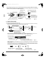
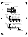
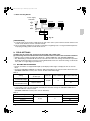
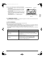
00_CV_3P156215-10P.fm Page 1 Friday, March 28, 2008 2:21 PM
INSTALLATION MANUAL
English
SYSTEM Inverter Air Conditioners
Deutsch
MODELS
Français
Wall-mounted type
Español
FXAQ20MAVE
FXAQ25MAVE
FXAQ32MAVE
FXAQ40MAVE
FXAQ50MAVE
FXAQ63MAVE
Italiano
ÅëëçíéêÜ
Nederlands
READ THESE INSTRUCTIONS CAREFULLY BEFORE INSTALLATION.
KEEP THIS MANUAL IN A HANDY PLACE FOR FUTURE REFERENCE.
LESEN SIE DIESE ANWEISUNGEN VOR DER INSTALLATION SORGFÄLTIG DURCH.
BEWAHREN SIE DIESE ANLEITUNG FÜR SPÄTERE BEZUGNAHME GRIFFBEREIT AUF.
LIRE SOIGNEUSEMENT CES INSTRUCTIONS AVANT L’INSTALLATION.
CONSERVER CE MANUEL A PORTEE DE MAIN POUR REFERENCE ULTERIEURE.
LEA CUIDADOSAMENTE ESTAS INSTRUCCIONES ANTES DE INSTALAR.
GUARDE ESTE MANUAL EN UN LUGAR A MANO PARA LEER EN CASO DE TENER
ALGUNA DUDA.
PRIMA DELL’INSTALLAZIONE LEGGERE ATTENTAMENTE QUESTE ISTRUZIONI.
TENERE QUESTO MANUALE A PORTATA DI MANO PER RIFERIMENTI FUTURI.
ÄΙΑΒΑΣΤΕ ΠΡΟΣΕΚΤΙΚΑ ΑΥΤΕΣ ΤΙΣ ΟÄΗΓΙΕΣ ΠΡΙΝ ΑΠΟ ΤΗΝ ΕΓΚΑΤΑΣΤΑΣΗ ΕΧΕΤΕ ΑΥΤΟ
ΤΟ ΕΓΧΕΙΡΙÄΙΟ ΕΥΚΑΙΡΟ ΓΙΑ ΝΑ ΤΟ ΣΥΜΒΟΥΛΕΥΕΣΤΕ ΣΤΟ ΜΕΛΛΟΝ.
LEES DEZE INSTRUCTIES ZORGVULDIG DOOR VOOR INSTALLATIE. BEWAAR DEZE HANDLEINDING WAAR U HEM KUNT TERUGVINDEN VOOR LATERE NASLAG.
LEIA COM ATENÇÃO ESTAS INSTRUÇÕES ANTES DE REALIZAR A INSTALAÇÃO.
MANTENHA ESTE MANUAL AO SEU ALCANCE PARA FUTURAS CONSULTAS.
ПЕРЕД НАЧАЛОМ МОНТАЖА ВНИМАТЕЛЬНО ОЗНАКОМЬТЕСЬ С ДАННЫМИ
ИНСТРУКЦИЯМИ. СОХРАНИТЕ ДАННОЕ РУКОВОДСТВО В МЕСТЕ, УДОБНОМ ДЛЯ
ОБРАЩЕНИЯ В БУДУЩЕМ.
Portugues
Ðóññêèé
3P086590-1A.fm Page 1 Thursday, February 13, 2003 9:03 AM
CE - DECLARATION OF CONFORMITY
CE - KONFORMITÄTSERKLÄRUNG
CE - DECLARATION DE CONFORMITE
CE - CONFORMITEITSVERKLARING
CE - DECLARACION DE CONFORMIDAD
CE - DICHIARAZIONE DI CONFORMITA’
CE - ÄΗΛÙΣΗ ΣΥΜΜΟΡΦÙΣΗΣ
CE - DECLARAÇÃO DE CONFORMIDADE
CE - OPFYLDELSESERKLÆRING
CE - FÖRSÄKRAN OM ÖVERENSTÄMMELSE
CE - ERKLÆRING OM SAMSVAR
CE - ILMOITUS YHDENMUKAISUUDESTA
DAIKIN INDUSTRIES, LTD.
declares under its sole responsibility that the air conditioning models to which this declaration relates:
erklärt auf seine alleinige Verantwortung daß die Modelle der Klimageräte für die diese Erklärung bestimmt ist:
déclare sous sa seule responsabilité que les appareils d’air conditionné visés par la présente déclaration:
verklaart hierbij op eigen exclusieve verantwoordelijkheid dat de airconditioning units waarop deze verklaring betrekking heeft:
declara baja su única responsabilidad que los modelos de aire acondicionado a los cuales hace referencia la declaración:
dichiara sotto sua responsabilità che i condizionatori modello a cui è riferita questa dichiarazione:
δηλþνει ìε αποκλειστικÞ τηò ευθýνη üτι τα ìοντÝλα των κλιìατιστικþν συσκευþν στα oπoßα αναφÝρεται η παροýσα δÞλωση:
declara sob sua exclusiva responsabilidade que os modelos de ar condicionado a que esta declaração se refere:
erklærer under eneansvar, at klimaanlægmodellerne, som denne deklaration vedrører:
deklarerar i egenskap av huvudansvarig, att luftkonditioneringsmodellerna som berörs av denna deklaration innebär att:
erklærer et fullstendig ansvar for at de luftkondisjoneringsmodeller som berøres av denne deklarasjon innebærer at:
ilmoittaa yksinomaan omalla vastuullaan, että tämän ilmoituksen tarkoittamat ilmastointilaitteiden mallit:
FXC20LVE, FXC25LVE, FXC32LVE, FXC40LVE, FXC50LVE, FXC63LVE, FXC80LVE, FXC125LVE
FXM40LVE, FXM50LVE, FXM63LVE, FXM80LVE, FXM100LVE, FXM125LVE, FXM200LVE, FXM250LVE
FXL20LVE, FXL25LVE, FXL32LVE, FXL40LVE, FXL50LVE, FXL63LVE
FXN20LVE, FXN25LVE, FXN32LVE, FXN40LVE, FXN50LVE, FXN63LVE
FXH32LVE, FXH63LVE, FXH100LVE
FXS20LVE, FXS25LVE, FXS32LVE, FXS40LVE, FXS50LVE, FXS63LVE, FXS80LVE, FXS100LVE, FXS125LVE
FXK25LVE, FXK32LVE, FXK40LVE, FXK63LVE
FXA20LVE, FXA25LVE, FXA32LVE, FXA40LVE, FXA50LVE, FXA63LVE
are in conformity with the following standard(s) or other normative document(s), provided that these are used in accordance with our instructions:
der/den folgenden Norm(en) oder einem anderen Normdokument oder -dokumenten entspricht/entsprechen, unter der Voraussetzung, daß sie gemäß unseren Anweisungen eingesetzt werden:
sont conformes à la/aux norme(s) ou autre(s) document(s) normatif(s), pour autant qu’ils soient utilisés conformément à nos instructions:
conform de volgende norm(en) of één of meer andere bindende documenten zijn, op voorwaarde dat ze worden gebruikt overeenkomstig onze instructies:
están en conformidad con la(s) siguiente(s) norma(s) u otro(s) documento(s) normativo(s), siempre que sean utilizados de acuerdo con nuestras instrucciones:
sono conformi al(i) seguente(i) standard(s) o altro(i) documento(i) a carattere normativo, a patto che vengano usati in conformità alle nostre istruzioni:
εßναι σýìφωνα ìε το(α) ακüλουθο(α) πρüτυπο(α) Þ Üλλο Ýγγραφο(α) κανονισìþν, υπü την προϋπüθεση üτι χρησιìοποιοýνται σýìφωνα ìε τιò οδηγßεò ìαò:
estão em conformidade com a(s) seguinte(s) norma(s) ou outro(s) documento(s) normativo(s), desde que estes sejam utilizados de acordo com as nossas instruções:
overholder følgende standard(er) eller andet/andre retningsgivende dokument(er), forudsat at disse anvendes i henhold til vore instrukser:
respektive utrustning är utförd i överensstämmelse med och följer följande standard(er) eller andra normgivande dokument, under förutsättning att användning sker i överensstämmelse med våra instruktioner:
respektive utstyr er i overensstemmelse med følgende standard(er) eller andre normgivende dokument(er), under forutssetning av at disse brukes i henhold til våre instrukser:
vastaavat seuraavien standardien ja muiden ohjeellisten dokumenttien vaatimuksia edellyttäen, että niitä käytetään ohjeidemme mukaisesti:
EN60335-2-40,
following the provisions of:
gemäß den Vorschriften der:
conformément aux stipulations des:
overeenkomstig de bepalingen van:
siguiendo las disposiciones de:
secondo le prescrizioni per:
ìε τÞρηση των διατÜξεων των:
de acordo com o previsto em:
under iagttagelse af bestemmelserne i:
enligt villkoren i:
gitt i henhold til bestemmelsene i:
noudattaen määräyksiä:
Directives, as amended.
Direktiven, gemäß Änderung.
Directives, telles que modifiées.
Low Voltage 73/23/EEC*
Machinery Safety 98/37/EC*
Electromagnetic Compatibility 89/336/EEC*
Richtlijnen, zoals geamendeerd.
Directivas, según lo enmendado.
Direttive, come da modifica.
Οδηγιþν, üπωò Ýχουν τροποποιηθεß.
Directivas, conforme alteração em.
Direktiver, med senere ændringer.
Direktiv, med företagna ändringar.
Direktiver, med foretatte endringer.
Direktiivejä, sellaisina kuin ne ovat muutettuina.
*Note
*Hinweis
*Remarque
as set out in the Technical Construction File DAIKIN.TCF.014 and judged positively by NMi according to the Certificate 9110074503.
wie in der Technischen Konstruktionsakte DAIKIN.TCF.014 aufgeführt und von NMi positiv ausgezeichnet gemäß Zertifikat 9110074503.
tel que stipulé dans le Fichier de Construction Technique DAIKIN.TCF.014 et jugé positivement par NMi conformément au Certificat 9110074503.
*Bemerk
*Nota
*Nota
zoals vermeld in het Technisch Constructiedossier DAIKIN.TCF.014 en in orde bevonden door NMi overeenkomstig Certificaat 9110074503.
tal como se expone en el Archivo de Construcción Técnica DAIKIN.TCF.014 y juzgado positivamente por NMi según el Certificado 9110074503.
delineato nel File Tecnico di Costruzione DAIKIN.TCF.014 e giudicato positivamente da NMi secondo il Certificato 9110074503.
*Σηìεßωση
*Nota
*Bemærk
üπωò προσδιορßζεται στο Αρχεßο ΤεχνικÞò ΚατασκευÞò DAΙΚΙΝ.ΤCF.014 και κρßνεται θετικÜ απü το NMi σýìφωνα ìε το Πιστοποιητικü 9110074503.
tal como estabelecido no Ficheiro Técnico de Construção DAIKIN.TCF.014 e com o parecer positivo de NMi de acordo com o Certificado 9110074503.
som anført i den Tekniske Konstruktionsfil DAIKIN.TCF.014 og positivt vurderet af NMi i henhold til Certifikat 9110074503.
*Information
*Merk
*Huom
utrustningen är utförd i enlighet med den Tekniska Konstruktionsfilen DAIKIN.TCF.014 som positivt intygas av NMi vilket också framgår av Certifikat 9110074503.
som det fremkommer i den Tekniske Konstruksjonsfilen DAIKIN.TCF.014 og gjennom positiv bedømmelse av NMi ifølge Sertifikat 9110074503.
jotka on esitetty Teknisessä Asiakirjassa DAIKIN.TCF.014 ja jotka NMi on hyväksynyt Sertifikaatin 9110074503 mukaisesti.
Umeda Center Bldg., 4-12, Nakazaki-Nishi 2-chome,
Kita-ku, Osaka, 530-8323 Japan
3P086590-1A
EN60335-2-40,
FXZQ20MVE, FXZQ25MVE, FXZQ32MVE, FXZQ40MVE, FXZQ50MVE
FXCQ20MVE, FXCQ25MVE, FXCQ32MVE, FXCQ40MVE, FXCQ50MVE, FXCQ63MVE, FXCQ80MVE, FXCQ125MVE
FXMQ40MVE, FXMQ50MVE, FXMQ63MVE, FXMQ80MVE, FXMQ100MVE, FXMQ125MVE, FXMQ200MVE, FXMQ250MVE
FXLQ20MVE, FXLQ25MVE, FXLQ32MVE, FXLQ40MVE, FXLQ50MVE, FXLQ63MVE
FXNQ20MVE, FXNQ25MVE, FXNQ32MVE, FXNQ40MVE, FXNQ50MVE, FXNQ63MVE
FXHQ32MVE, FXHQ63MVE, FXHQ100MVE
FXSQ20MVE, FXSQ25MVE, FXSQ32MVE, FXSQ40MVE, FXSQ50MVE, FXSQ63MVE, FXSQ80MVE, FXSQ100MVE, FXSQ125MVE
DAIKIN INDUSTRIES, LTD.
3P109591-1E
Noboru Murata
Manager Quality Control Department
1st of November 2005
FXKQ25MVE, FXKQ32MVE, FXKQ40MVE, FXKQ63MVE
FXAQ20MVE, FXAQ25MVE, FXAQ32MVE, FXAQ40MVE, FXAQ50MVE, FXAQ63MVE
FXUQ71MV1, FXUQ100MV1, FXUQ125MV1
BEVQ71MVE, BEVQ100MVE, BEVQ125MVE
FXMQ125MFV1, FXMQ200MFV1, FXMQ250MFV1
FXAQ20MHV1, FXAQ25MHV1, FXAQ32MHV1, FXAQ40MHV1, FXAQ50MHV1
BEVQ50MVE
0305020101
TNO
DAIKIN.TCF.022
FXHQ32MAVE, FXHQ63MAVE, FXHQ100MAVE
FXKQ25MAVE, FXKQ32MAVE, FXKQ40MAVE, FXKQ63MAVE
FXAQ20MAVE, FXAQ25MAVE, FXAQ32MAVE, FXAQ40MAVE
FXAQ50MAVE, FXAQ63MAVE
FXUQ71MAV1, FXUQ100MAV1, FXUQ125MAV1
BEVQ71MAVE, BEVQ100MAVE, BEVQ125MAVE
Umeda Center Bldg., 4-12, Nakazaki-Nishi 2-chome,
Kita-ku, Osaka, 530-8323 Japan
FXLQ20MHV1, FXLQ25MHV1, FXLQ32MHV1, FXLQ40MHV1, FXLQ50MHV1,
FXMQ40MAVE, FXMQ50MAVE, FXMQ63MAVE, FXMQ80MAVE
FXMQ100MAVE, FXMQ125MAVE, FXMQ200MAVE, FXMQ250MAVE
FXLQ20MAVE, FXLQ25MAVE, FXLQ32MAVE, FXLQ40MAVE
FXLQ50MAVE, FXLQ63MAVE
FXNQ20MAVE, FXNQ25MAVE, FXNQ32MAVE, FXNQ40MAVE
FXNQ50MAVE, FXNQ63MAVE
01_EN_3P156215-10P.fm Page 1 Wednesday, April 2, 2008 11:47 AM
FXAQ20MAVE
FXAQ25MAVE
FXAQ32MAVE
FXAQ40MAVE
FXAQ50MAVE
FXAQ63MAVE
VRV SYSTEM
Inverter Air Conditioners
Installation manual
CONTENTS
1.
2.
3.
4.
5.
6.
7.
8.
9.
10.
SAFETY CONSIDERATIONS ........................................................................................ 1
BEFORE INSTALLATION .............................................................................................. 2
SELECTING INSTALLATION SITE ............................................................................... 4
INDOOR UNIT INSTALLATION ..................................................................................... 5
REFRIGERANT PIPING WORK .................................................................................... 9
DRAIN PIPING WORK................................................................................................. 11
ELECTRIC WIRING WORK ......................................................................................... 12
HOW TO CONNECT WIRINGS AND WIRING EXAMPLE .......................................... 13
FIELD SETTINGS ........................................................................................................ 16
TEST OPERATION ...................................................................................................... 18
1. SAFETY CONSIDERATIONS
Please read these “SAFETY CONSIDERATIONS” carefully before installing air conditioning equipment and
be sure to install it correctly. After completing the installation, make sure that the unit operates properly during
the start-up operation. Please instruct the customer on how to operate the unit and keep it maintained.
Also, inform customers that they should store this installation manual along with the operation manual for
future reference.
This air conditioner comes under the term “appliances not accesible to the general public”.
Meaning of warning and caution symbols.
WARNING ........Failure to observe a warning may result in death or serious injury.
CAUTION ..........Failure to observe a caution may result in injury or damage to the equipment.
•
•
•
•
•
•
•
1
WARNING
Ask your dealer or qualified personnel to carry out installation work. Do not try to install the machine yourself.
Improper installation may result in water leakage, electric shocks or fire.
Perform installation work in accordance with this installation manual.
Improper installation may result in water leakage, electric shocks or fire.
When installing the unit in a small room, take measures against to keep refrigerant concentration from
exceeding allowable safety limits in the event of refrigerant leakage. Contact the place of purchase for more
information. Excessive refrigerant in a closed ambient can lead to oxygen deficiency.
Be sure to use only the specified accessories and parts for installation work.
Failure to use the specified parts may result in water leakage, electric shocks, fire or the unit falling.
Install the air conditioner on a foundation strong enough to withstand the weight of the unit.
A foundation of insufficient strength may result in the equipment falling and causing injuries.
Carry out the specified installation work after taking into account strong winds, typhoons or earthquakes.
Improper installation work may result in the equipment falling and causing accidents.
Make sure that a separate power supply circuit is provided for this unit and that all electrical work is carried
out by qualified personnel according to local laws and regulations and this installation manual.
An insufficient power supply capacity or improper electrical construction may lead to electric shocks or fire.
English
01_EN_3P156215-10P.fm Page 2 Wednesday, April 2, 2008 11:47 AM
• Make sure that all wiring is secured, the specified wires are used, and no external forces act on the terminal
connections or wires.
Improper connections or installation may result in fire.
• When wiring the power supply and connecting the wiring between the indoor and outdoor units, position the
wires so that the control box cover can be securely fastened.
Improper positioning of the control box cover may result in electric shocks, fire or the terminals
overheating.
• If the refrigerant gas leaks during installation, ventilate the area immediately.
Toxic gas may be produced if the refrigerant gas comes into contact with fire.
• After completing the installation work, check that the refrigerant gas does not leak.
Toxic gas may be produced if the refrigerant gas leaks into the room and comes into contact with a source
of fire, such as a fan heater, stove or cooker.
• Before touching electrical parts, turn off the unit.
• Be sure to establish an earth.
Do not earth the unit to a utility pipe, arrester, or telephone earth.
Incomplete earth may cause electrical shock, or fire.
A high surge current from lightning or other sources may cause damage to the air conditioner.
• Be sure to install an earth leakage breaker.
Failure to install an earth leakage breaker may result in electric shocks, or fire.
•
•
•
•
CAUTION
While following the instructions in this installation manual, install drain piping in order to ensure proper
drainage and insulate piping in order to prevent condensation.
Improper drain piping may result in water leakage and property damage.
Install the indoor and outdoor units, power cord and connecting wires at least 1 meter away from televisions
or radios in order to prevent image interference or noise.
(Depending on the radio waves, a distance of 1 meter may not be sufficient enough to eliminate the noise.)
Remote controller (wireless kit) transmitting distance can result shorter than expected in rooms with
electronic fluorescent lamps. (inverter or rapid start types)
Install the indoor unit as far away from fluorescent lamps as possible.
Do not install the air conditioner in the following locations:
(a) where a mineral oil mist or an oil spray or vapor is produced, for example in a kitchen
Plastic parts may deteriorate and fall off or result in water leakage.
(b) where corrosive gas, such as sulfurous acid gas, is produced
Corroding copper pipes or soldered parts may result in refrigerant leakage.
(c) near machinery emitting electromagnetic waves
Electromagnetic waves may disturb the operation of the control system and result in a malfunction of
the equipment.
(d) where flammable gases may leak, where there are carbon fiber or ignitable dust suspensions in the air,
or where volatile flammables such as thinner or gasoline are handled.
Operating the unit in such conditions may result in fire.
2. BEFORE INSTALLATION
Do not exert pressure on the resin parts when opening the unit or when moving it after opening.
Before rigging tubes, check which type of refrigerant is used. Proper operation is not possible if the
types of refrigerant are not the same.
• Be careful not to bend any of the plastic parts when moving the unit when taking it out of the packing case or
afterwards.
• Decide upon a line of transport.
• When transporting, transport to the installation location without taking it out of the packing case.
If you have to remove the unit from the packing case when transporting it, be sure not to damage it.
• Refer to the installation manual of the outdoor unit for items not described in this manual.
• Do not dispose of any parts necessary for installation until the installation is complete.
English
2
01_EN_3P156215-10P.fm Page 3 Wednesday, April 2, 2008 11:47 AM
2-1 PRECAUTIONS
• Be sure to read this manual before installing the indoor unit.
• Entrust installation to the place of purchase or a qualified serviceman.Improper installation could lead to
leaks and, in worse cases, electric shock of fire.
• Use only parts provided with the unit or parts satisfing required specifications. Unspecified parts could
cause the unit to fall out of place, or could lead to leaks and, in worse cases, electric shock or fire.
• Do not install or operate the unit in rooms mentioned below.
• Laden with mineral oil, or filled with oil vapor or spray like in kitchens. (Plastic parts may
deteriorate which could eventually cause the unit to fall out of place, or could lead to leaks.)
• Where corrosive gas like sulfurous gas exists. (Copper tubing and brazed spots may corrode,
which could eventually lead to refrigerant leaks.)
• Where volatile flammable gas like thinner or gasoline is used.
• Where exposed to combustible gases and where voltatile flammable gas like thinner or gasoline
is used. (Gas in the vicinity of the unit could ignite.)
• Where machines can generate electromagnetic waves. (Control system may malfunction.)
• Where the air contains high levels of salt such as that near the ocean and where voltage
fluctuates greatly such as that in factories. Also in vehicles or vessels.
• When selecting installation site, refer to the installation pattern.
• This unit, both indoor and outdoor, is suitable for installation in a commercial and light industrial
environment. If installed as a household appliance it could cause electromagnetic interference.
2-2 ACCESSORIES
Check the following accessories are included with your unit.
(1) Installation
panel
Name
Quantity
1 set
(2) Attachment screws
for the installation panel
8 pcs. → FXA(Q)20,25,32 type
9 pcs. → FXA(Q)40,50,63 type
(3) Paper pattern
(4) Insulating tape
for installation
1 pc.
1 pc.
Shape
M4 × 25L
Name
Quantity
(5) Clamp
1 large 3 small
(6) Securing screws
2 pcs.
(Other)
• Operation manual
• Installation manual
Shape
M4 × 12L
2-3 OPTIONAL ACCESSORIES
• These are two types of remote controllers: wired and wireless. Select a remote controller according to
customer request and install in an appropriate place.
Remote controller type
Wired type
Wireless type
Heat pump type
Cooling only
type
Model
BRC1C51
BRC1A61
BRC7E618
BRC7E619
• If the customer wishes to use a remote controller that is not listed above, select a suitable remote
controller after consulting catalogs and technical materials.
3
English
01_EN_3P156215-10P.fm Page 4 Wednesday, April 2, 2008 11:47 AM
FOR THE FOLLOWING ITEMS, TAKE SPECIAL CARE DURING CONSTRUCTION AND
CHECK AFTER INSTALLATION IS FINISHED.
1. Items to be checked after completion of work
Items to be checked
Are the indoor and outdoor unit fixed
firmly?
Is the gas leak test finished?
Is the unit fully insulated?
Does drainage flow smoothly?
Does the power supply voltage correspond
to that shown on the name plate?
Are wiring and piping correct?
Is the unit safely grounded?
Is wiring size according to specifications?
Is something blocking the air outlet or inlet
of either the indoor or outdoor units?
Are refrigerant piping length and additional
refrigerant charge noted down?
If not properly done, what is likely to occur
Check
The units may drop, vibrate or make noise.
It may result in insufficient cooling.
Condensate water may drip.
Condensate water may drip.
The unit may malfunction or the
components burn out.
The unit may malfunction or the
components burn out.
Dangerous at electric leakage.
The unit may malfunction or the
components burn out.
It may result in insufficient cooling.
The refrigerant charge in the system is not
clear.
2. Items to be checked at time of delivery
* Also review the “SAFETY CONSIDERATIONS”
Items to be checked
Check
Did you explain about operations while showing the operation manual to your customer?
Did you hand the operation manual over to your customer?
Points for explanation about operations
The items with
WARNING and
CAUTION marks in the instruction manual are the items
pertaining to possibilities for bodily injury and material damage in addition to the general usage of
the product. Accordingly, it is necessary that you make a full explanation about the described
contents and also ask your customers to read the instruction manual.
2-4 NOTE TO THE INSTALLER
Be sure to instruct customers how to properly operate the unit (especially cleaning filters, operating different
functions, and adjusting the temperature) by having them carry out operations themselves while looking at the
manual.
3. SELECTING INSTALLATION SITE
(1) Select an installation site where the following conditions are fulfilled and that meets with your
customer’s approval.
• In the upper space (including the back of the ceiling) of the indoor unit where there is no possible
dripping of water from the refrigerant pipe, drain pipe, water pipe, etc.
• Where the wall is strong enough to bear the indoor unit weight.
• Where sufficient clearance for installation and maintenance can be ensured.
(Refer to Fig. 1 and Fig. 2)
English
4
01_EN_3P156215-10P.fm Page 5 Wednesday, April 2, 2008 11:47 AM
•
•
•
•
•
•
Where optimum air distribution can be ensured.
Where nothing blocks the air passage.
Where condensate can be properly drained.
Where the wall is not significantly tilted.
Where not exposed to combustible gases.
Where pipe between indoor and outdoor units is possible within the allowable limit.
(Refer to the installation manual of the outdoor unit.)
• Install the indoor and outdoor units, power cable and transmission wiring, at least 1 m from TVs and
radios, to prevent distorted pictures and static. (Depending on the type and source of the electrical
waves, static may be heard even when more than 1 m away.)
• Install the indoor unit no less than 2.5 m above the floor. Where unavoidably lower, take what measures
are necessary to keep hands out of the air inlet.
• Where the cool (warm) air reaches all across the room.
[ Space required for installation (mm) ]
≥ 50
≥ 30
≥ 90
≥ 50
Fig. 1
Obstruction
≤ 120
≥ 2500 (from floor)
For installation
in high places.
Floor
Fig. 2
(2) Consider whether the place where the unit will be installed can support the full weight of the unit,
and reinforce it with boards and beams, etc. if needed before proceeding with the installation.
Also, reinforce the place to prevent vibration and noise before installing.
(The installation pitch can be found on the paper pattern for installation (3), so refer to it when considering the necessity for reinforcing the location.)
(3) The indoor unit may not be directly installed on the wall. Use the attached installation panel (1)
before installing the unit.
4. INDOOR UNIT INSTALLATION
• Use only accessories and parts which are of the designated specification when installing.
CAUTION
• Install so that the unit does not tilt to either side or forward.
• Do not hold the unit by the horizontal flaps when lifting it. (This may damage the horizontal flaps.)
(1) Open the piping through-hole.
• The refrigerant pipe and drain pipe can be passed out in one of 6 directions: left, bottom-left, back-left,
right, bottom-right, and back-right. (Refer to Fig. 3)
5
English
01_EN_3P156215-10P.fm Page 6 Wednesday, April 2, 2008 11:47 AM
• Using the paper pattern for installation (3), choose where to pass the piping out and open a through-hole
(φ80) in the wall.
Open the hole so that there is a downward slope for the drain piping. (See “ 6.DRAIN PIPING WORK ”)
(2) Remove the installation panel (1) from the unit and attach to the wall.
(The installation panel is temporarily attached to the unit with screw. (In case of 20-32 type))
(Refer to Fig. 3)
(a) Check the location for the hole using the included paper pattern for installation (3).
• Choose a location so that there is at least a 90 mm gap between the ceiling and the main unit.
(b) Temporarily attach the installation panel (1) at the temporary-securing position on the paper pattern for
installation (3) and use a level to make sure the drain hose is either level or tilted slightly downward.
(c) Secure the installation panel (1) to the wall using either screws or bolts.
• If using the attachment screws for the installation panel (2), attach using at least 4 screws on either
side (for a total of 8 screws (20-32 type), 9 screws (40-63 type)) of the recommended installation
cleat position on the included paper pattern for installation (3).
• If using bolts, attach using a M8 - M10 bolt (for a total of 2 bolts) on either side.
• If dealing with concrete, use commercially available foundation bolts (M8 - M10).
(3) If using the left, bottom-left, right, or bottom-right positions for the piping, cut out the through-hole
for the piping in the front grill. (Refer to Fig. 4)
Installation panel (1)
Temporary screw
(In case of 20-32 type)
Front grill
Left pipe
Cut out along
the groove.
Back-left pipe
Bottom-left pipe
Cut away
Back-right pipe
Fig. 3
Right pipe
Fig. 4
Bottom-right pipe
(4) Remove the front panel and the service lid. (Refer to Fig. 5)
< How to remove the front panel and service lid >
(1) Open the front panel to the point where it stops.
(2) Push the axes on either side of the front panel towards the center of the main unit and remove. (You can
also remove it by sliding the front panel either to the left or right and pulling it forward.)
(3) Remove the screw from the service lid and pull the handle forward.
Axis
(1)
Front panel
Axis
(2)
Service lid
(2)
(3)
Handle
Axis
Fig. 5
English
Screw
6
01_EN_3P156215-10P.fm Page 7 Wednesday, April 2, 2008 11:47 AM
(5) Point the pipe in the direction it will be passed out.
For right, bottom-right, and back-right piping (Refer to Fig. 6)
• Wrap the drain hose and the refrigerant piping together with the insulating tape (4) so that the drain hose is below the refrigerant piping.
Insulating tape (4)
Refrigerant piping
For left, bottom-left, and left-back piping
• Remove the front grill. (Refer to Fig. 7)
< How to remove the front grill >
Remove the front grill as described below when securing the indoor
Drain hose
unit with screws or when attaching Optional Accessories (wireless
Fig. 6
remote controller, adapter PC board, etc.).
(1) Remove the front panel.
(2) Remove the screws (2 places in case of FXA(Q)20,25,32 type/3 places in case of FXA(Q)40,50,63
type) securing the front grill.
(3) Remove the tabs (3 places) securing the front grill by pushing them in the direction of the arrows.
(4) Making sure not to catch the horizontal flaps, remove the front grill by pulling in the direction of the arrow.
Tab position
(3)
(3)
Tab
Tab position
(3)
Front grill
(4)
Screw position
(2)
(2)
(2)
Fig. 7
Screw position (In case of FXA(Q)40,50,63 type)
• Remove the drain plug, the insulation tubing, and the drain hose from the drain pan and replace.
(Refer to Fig. 8)
• Connect the local refrigerant piping ahead of time, matching it to the liquid pipe and gas pipe marks
engraved on the installation panel (1).
< Replacing the drain hose and drain plug >
(1) Remove the drain plug and insulation tubing.
(2) Remove the drain hose and replace onto the left side.
(3) Replace the drain plug and the insulation tubing onto the right side.
Insulating tube
Make sure
there are
no gaps.
Fig. 8
7
Drain plug
Do not place lubricant (refrigerant oil) when inserting.
This may cause deterioration and water leaks.
Insert using a hexagon wrench (4mm).
English
01_EN_3P156215-10P.fm Page 8 Wednesday, April 2, 2008 11:47 AM
(6) Hook the indoor unit onto the installation panel. (Refer to Fig. 9)
• Placing buffering material between the wall and the indoor unit at this time will make work easier.
Service lid
Front panel
Hook the indoor unit hook onto the installation panel (1).
Front grill
Place buffering material
Wall
Be sure to pass all wires through
the wiring guide.
Refrigerant piping
Wiring (locally procured)
Tab
(There are 2 places.)
Installation panel
(accessory) (1)
Power supply wiring, Transmission wiring, Ground wiring,
Remote controller wiring
Fig. 9
For right, bottom-right, and back-right piping
• Pass the drain hose and the refrigerant piping to the wall.
(7) Pass power supply wiring, transmission wiring, ground wiring, and remote controller wiring
through the wiring guide in through the back of the indoor unit and to the front.
(8) Connect the piping. (See “5.REFRIGERANT PIPING WORK” and Fig. 10)
Power supply wiring and
ground wiring
Refrigerant piping
Secure with
vinyl tape.
Drain hose
Refrigerant piping
Seal with putty corking
material.
Transmission wiring and
remote controller wiring
A
Wiring
A arrow view
Wrap the insulating tape overlapping at least half the width with
each wrap.
Wrap the insulating tape all the way to the L-shaped bend.
Fig. 10
• To avoid the influence of noise from the power supply line on the transmission wiring and the remote
controller wiring, these wirings must be kept as far as possible from the power/ground wirings. As shown in the
figure, keep the power supply wiring and the ground wiring together. Keep the transmission and remote controller wirings together and route them maintaining a good distance from the power supply/ground wirings
(that is, on the other side of the power supply/ground wirings). Then, fix them securely on the refrigerant pipe.
• Seal the piping through-hole with putty corking material.
(9) Push on both bottom edges of the indoor unit using both hands and hook the tab on the back of
the indoor unit onto the installation panel (1). (Refer to Fig. 9)
• At this time remove the buffering material placed in step (6).
English
8
01_EN_3P156215-10P.fm Page 9 Wednesday, April 2, 2008 11:47 AM
• Make sure power supply wiring, transmission wiring, ground wiring and remote controller wiring are not
caught inside the indoor unit.
■ When screwing in the indoor unit
Installation panel
(accessory) (1)
• Remove the front grill. (Refer to Fig. 7)
• Secure the indoor unit to the installation panel (1) with the securing
screws (6). (Refer to Fig. 11)
Refrigerant piping
Insulating tape
(accessory) (4)
M4 × 12L
(accessory) (6)
Fig. 11
5. REFRIGERANT PIPING WORK
〈For refrigerant piping of outdoor units, see the installation manual attached to the outdoor unit.〉
〈Execute heat insulation work completely on both sides of the gas piping and the liquid piping.
Otherwise, a water leakage can result sometimes.〉
(When using a heat pump, the temperature of the gas piping can reach up to approximately 120°C, so use
insulation which is sufficiently resistant.)
〈Also, in cases where the temperature and humidity of the refrigerant piping sections might exceed
30°C or RH80 %, reinforce the refrigerant insulation. (20 mm or thicker) Condensation may form on the
surface of the insulating material.〉
〈Before refrigerant piping work, check which type of refrigerant is used. Proper operation is not possible if the types of refrigerant are not the same.〉
•
•
•
•
CAUTION
Use a pipe cutter and flare suitable for the type of refrigerant.
Apply ester oil or ether oil around the flare section before connecting.
To prevent dust, moisture or other foreign matter from infiltrating the tube, either pinch the end
or cover it with tape.
Do not allow anything other than the designated refrigerant to get mixed into the refrigerant
circuit, such as air, etc. If any refrigerant gas leaks while working on the unit, ventilate the room
thoroughly right away.
• The outdoor unit is charged with refrigerant.
• Use copper alloy seamless pipes (ISO 1337)
• Be sure to use both a spanner and torque wrench together, as shown
in the drawing, when connecting or disconnecting pipes to/from the
unit. (Refer to Fig. 12)
• Refer to “Table 1” for the dimensions of flare nut spaces.
• When connecting the flare nut, coat the flare section (both inside and
outside) with ester oil or ether oil, rotate three or four times first, then
screw in. (Refer to Fig. 13)
CAUTION
• Over-tightening may cause the flare nuts to crack or the refrigerant
to leak.
• Use the flare nut included with the unit main body.
Torque wrench
Spanner
Piping union
Flare nut
Fig. 12
Ester oil or ether oil
Fig. 13
9
English
01_EN_3P156215-10P.fm Page 10 Wednesday, April 2, 2008 11:47 AM
• Refer to Table 1 for tightening torque.
Table 1
Flare dimensions A (mm)
Flare
FXAQ–M(A)VE
φ 6.4 (1/4”)
14.2 – 17.2N·m
8.6 – 9.0
8.7 – 9.1
φ 9.5 (3/8”)
32.7 – 39.9N·m
12.6 – 13.0
12.8 – 13.2
φ 12.7 (1/2”)
49.5 – 60.3N·m
15.8 – 16.2
16.2 – 16.6
φ 15.9 (5/8”)
61.8 – 75.4N·m
19.0 – 19.4
19.3 – 19.7
R0.4-0.8
A
FXA–LVE(C)
45 0±2 0
Tightening torque
900±20
Pipe size
Not recommendable but in case of emergency
You must use a torque wrench but if you are obliged to install the unit without a torque wrench, you may
follow the installation method mentioned below.
After the work is finished, make sure to check that there is no gas leak.
When you keep on tightening the flare nut with a spanner, there is a point where the tightening torque
suddenly increases. From that position, further tighten the flare nut the angle shown below:
Table 2
Pipe size
φ 6.4 (1/4”)
φ 9.5 (3/8”)
φ12.7 (1/2”)
φ15.9 (5/8”)
Further tightening angle
60 to 90 degrees
60 to 90 degrees
30 to 60 degrees
30 to 60 degrees
Recommended arm length of tool
Approx. 150mm
Approx. 200mm
Approx. 250mm
Approx. 300mm
CAUTION
CAUTION TO BE TAKEN WHEN BRAZING REFRIGERANT PIPING
“Do not use flux when brazing refrigerant piping. Therefore, use the phosphor copper brazing filler metal
(BCuP-2: JIS Z 3264/B-Cu93P-710/795: ISO 3677) which does not require flux.”
(Flux has extremely harmful influence on refrigerant piping systems. For instance, if the chlorine based flux is
used, it will cause pipe corrosion or, in particular, if the flux contains fluorine, it will damage the refrigerant oil.)
• When brazing the refrigerant piping, only begin brazing after having carried out nitrogen substitution
(NOTE 1) or while inserting nitrogen into the refrigerant piping (NOTE 2). Once this is done, connect the
indoor unit with a flared or a flanged connection.
NOTES
1. Refer to the “Manual for Multi Installation for Buildings” for directions on how to carry out nitrogen
substitution. (Inquire with your dealer.)
2. Nitrogen should be set to 0.02 MPa with a pressure-reducing valve if brazing while inserting nitrogen into
the piping. (Refer to Fig. 14)
Pressure-reducing valve
Refrigerant piping
Part to be
brazed
Nitrogen
Taping
hands valve
Nitrogen
Fig. 14
CAUTION
Be sure to insulate any field piping all the way to the piping connection inside the unit. Any exposed piping
may cause condensation or burns if touched.
English
10
01_EN_3P156215-10P.fm Page 11 Wednesday, April 2, 2008 11:47 AM
• After checking for gas leaks, be sure to insulate the pipe connections using the supplementary piping
insulation tubing and insulating tape (4). The insulating tape (4) should be wrapped from the L-shaped bend
all the way to the end inside the unit. (Refer to Fig. 15)
Indoor unit piping insulation tubing
Clamping material large
(accessory) (5)
Insulating tubing tape
Insulating tubing tape
Insulating tubing tape
Local piping
L-shaped
bend
Indoor unit piping
Indoor unit piping insulation tubing
Insulation tubing seam
Attach the insulation tubing
tape so that there are no gaps
in the insulation tubing seam.
Insulating tape (accessory) (4)
See “ 4.INDOOR UNIT
INSTALLATION ”
Start wrapping
Fig. 15
6. DRAIN PIPING WORK
(1) Install the drain piping. (Refer to Fig. 16)
• The drain pipe should be short with a downward slope and should prevent air pockets from forming.
• Watch out for the points in the figure 16 when performing drain work.
Make sure the drain
hose is at a downward
slope.
Make sure the tip does
not go underwater even
when water is added.
Drain hose
Drain hose
(Downward
slope)
Fig. 16
• When extending the drain hose, use a commercially available drain extension hose, and be sure to
insulate the extended section of the drain hose which is indoors. (Refer to Fig. 17)
Indoor unit drain hose
Extension drain piping
(commercially available)
Insulating tube
(commercially available)
Insulating tape (accessory) (4)
( See “4.INDOOR UNIT INSTALLATION” )
Fig. 17
• Make sure the diameter of the piping is the same as the piping (hard vinyl chloride, nominal diameter
13mm) or bigger.
• When directly connecting a hard vinyl chloride pipe joint (nominal diameter 13mm) to the drain hose
connected to the indoor unit (i.e. for embedded piping, etc.), use a commercially available hard vinyl
chloride pipe joint (nominal diameter 13mm). (Refer to Fig. 18)
Drain hose connected
to the indoor unit
11
Commercially available
hard vinyl chloride pipe
joint (nominal diameter 13mm)
Commercially available
hard vinyl chloride pipe
(nominal diameter 13mm)
Fig. 18
English
01_EN_3P156215-10P.fm Page 12 Wednesday, April 2, 2008 11:47 AM
(2) Make sure the drain works properly.
• After drain work is complete, perform a drain
check by opening the front panel, removing
the air filter, pouring water into the drain pan,
and making sure water flows smoothly out of
the drain hose. (Refer to Fig. 19)
Plastic container
for pouring
Drain pan
Fig. 19
Make sure not to splash the water.
CAUTION
Drain piping connections
Do not connect the drain piping directly to sewage pipes that smell of ammonia. The ammonia in the
sewage might enter the indoor unit through the drain pipes and corrode the heat exchanger.
Keep in mind that it will become the cause of getting drain pipe blocked if water collects on drain pipe.
7. ELECTRIC WIRING WORK
7-1 GENERAL INSTRUCTIONS
•
•
•
•
•
•
•
•
•
•
All field supplied parts and materials and electric works must conform to local codes.
Use copper wire only.
For electric wiring work, refer to also “WIRING DIAGRAM” attached to the unit body.
For remote controller wiring details, refer to the installation manual attached to the remote controller.
All wiring must be performed by an authorized electrician.
This system consists of multiple indoor units. Mark each indoor unit as unit A, unit B..., and be sure the
terminal board wiring to the outdoor unit and BS unit are properly matched. If wiring and piping between the
outdoor unit and an indoor unit are mismatched, the system may cause a malfunction.
A circuit breaker capable of shutting down power supply to the entire system must be installed.
Refer to the installation manual attached to the outdoor unit for the size of power supply wiring connected
to the outdoor unit, the capacity of the circuit breaker and switch, and wiring instructions.
Be sure to ground the air conditioner.
Do not connect the ground wire to gas pipes, water pipes, lightning rods, or telephone ground wires.
• Gas pipes: might cause explosions or fire if gas leaks.
• Water pipes: no grounding effect if hard vinyl piping is used.
• Telephone ground wires or lightning rods: might cause abnormally high electric potential in the ground
during lighting storms.
7-2 ELECTRICAL CHARACTERISTICS
Model
FXA(Q)20LVE(M(A)VE)
FXA(Q)25LVE(M(A)VE)
FXA(Q)32LVE(M(A)VE)
FXA(Q)40LVE(M(A)VE)
FXA(Q)50LVE(M(A)VE)
FXA(Q)63LVE(M(A)VE)
FXA(Q)20LVE(M(A)VE)
FXA(Q)25LVE(M(A)VE)
FXA(Q)32LVE(M(A)VE)
FXA(Q)40LVE(M(A)VE)
FXA(Q)50LVE(M(A)VE)
FXA(Q)63LVE(M(A)VE)
Units
Hz
Volts
Voltage range
50
220 - 240
Max. 264
Min. 198
60
220
Max. 242
Min. 198
MCA: Min. Circuit Amps (A);
kW: Fan Motor Rated Output (kW);
English
Power supply
MCA
MFA
0.3
15
0.4
15
0.4
15
0.4
15
0.4
15
0.6
15
0.3
15
0.3
15
0.4
15
0.4
15
0.4
15
0.6
15
Fan motor
kW
FLA
0.04
0.2
0.04
0.3
0.04
0.3
0.043
0.3
0.043
0.3
0.043
0.5
0.04
0.2
0.04
0.2
0.04
0.3
0.043
0.3
0.043
0.3
0.043
0.5
MFA: Max. Fuse Amps (A)
FLA: Full Load Amps (A)
12
01_EN_3P156215-10P.fm Page 13 Wednesday, April 2, 2008 11:47 AM
7-3 SPECIFICATIONS FOR FIELD SUPPLIED FUSES AND WIRE
Remote controller wiring
Transmission wiring
Power supply wiring
Model
Field fuses
FXA(Q)20LVE(M(A)VE)
FXA(Q)25LVE(M(A)VE)
FXA(Q)32LVE(M(A)VE)
FXA(Q)40LVE(M(A)VE)
FXA(Q)50LVE(M(A)VE)
FXA(Q)63LVE(M(A)VE)
15A
Wire
Size
Wire
Size
H05VV - U3G
Wire size must
comply with
local codes.
Vinyl cord with
sheath or cable
(2 wire)
0.75 - 1.25 mm2
Allowable length of transmission wirings and remote controller wiring are as follows.
(1) Outdoor unit - Indoor unit:
Max. 1000m (Max. wiring length: 2000m)
(2) Indoor unit - Remote controller:
Max. 500m
8. HOW TO CONNECT WIRINGS AND WIRING EXAMPLE
8-1 HOW TO CONNECT WIRINGS
Methods of wiring power supply, units and connecting remote controller wiring
• Power supply wiring
Unscrew and remove the service lid.
Connect the power supply wiring and ground wiring to the power supply terminal block (3P).
When doing this, tie the power supply wiring and the ground wiring using the included clamp (small) (5) and
then firmly secure using the included clamp (small) (5) according to the figure.
(Refer to Fig. 20)
• Transmission wiring and remote controller wiring
Unscrew and remove the service lid.
Connect the remote controller wiring and the transmission wiring to the terminal block (6P).
When doing this, tie the remote controller wiring and the transmission wiring using the included clamp (small)
(5) and then firmly secure using the included clamp (small) (5) according to the figure. (Refer to Fig. 20)
< Wiring clamp method >
Clamp small
(accessory) (5)
Power supply
terminal block (3P)
In case of using the power
supply terminal together with
the other connecting wirings
Clamp after tying the
wiring between the units
and the ground wiring.
Ground terminal
L
L
N
Power supply wiring Transmission
wiring
Ground wiring
Remote controller
wiring
N
Ground wiring
Make sure to process
the insulation at the wire
terminal part properly so that
the terminals do not get in
contact each other.
Clamp small
(accessory) (5)
Power supply wiring
Remote
controller wiring
P1 P2 F1 F2 T1 T2
REMOTE TRANSMISSION FORCED
CNTRL WIRING
OFF
Terminal block (6P)
Clamp small
(accessory) (5)
(3 places)
Cut off any excess
material after tightening.
Transmission wiring
Fig. 20
13
English
01_EN_3P156215-10P.fm Page 14 Wednesday, April 2, 2008 11:47 AM
CAUTION
Be sure to attach the sealing material and putty (field supplied) to hole of wiring to prevent the infiltration
of water as well as any insects and other small creatures from outside. Otherwise a short-circuit may
occur inside the electric parts box.
When clamping the wirings, be sure no pressure is applied to the wire connections by using the included
clamp to make appropriate clamps. Also, when wiring, make sure the lid on the control box fits snugly by
arranging the wirings neatly and attaching the service lid firmly. When attaching the service lid, make sure
no wirings get caught in the edges. Pass wiring through the wiring through holes to prevent damage to
them.
Make sure the remote controller wiring, and transmission wire the wiring between the units, and other electrical wiring do not pass through the same locations outside the machine, separating them by at least
50mm, otherwise electrical noise (external static) could cause mistaken operation or breakage.
Use only specified wire and tightly connect wires to terminals. Be careful wires do not place external stress
on terminals. Keep wiring in neat order and so as not to obstruct other equipment such as popping open the
service cover. Make sure the cover closes tight. Incomplete connections could result in overheating, and in
worse case, electric shock or fire.
[ PRECAUTIONS ]
1. Use round crimp-style terminals for connecting wires to the power supply terminal board.
(Refer to Fig. 21)
If unavailable, observe the following points when wiring.
• Do not connect wires of different gauge to the same power supply terminal.
(Looseness in the connection may cause overheating.)
• When connecting wires of the same gauge, connect them according to Fig. 22.
• Use the specified electric wire. Connect the wire securely to the terminal. Lock the wire down without
applying excessive force to the terminal. (Tightening torque: 131N·cm ±10 %)
Attach insulation sleeve
Round crimp-style terminal
Electric wire
Fig. 21
2. Tightening torque for the terminal screws.
• Use the correct screwdriver for tightening the terminal screws. If the blade of screwdriver is too small, the
head of the screw might be damaged, and the screw will not be properly tightened.
• If the terminal screws are tightened too hard, screws might be damaged.
• Refer to the table below for the tightening torque of the terminal screws.
Terminal
Remote controller, Transmission wiring and
Forced off terminal block (6P)
Power supply and Ground terminal block (3P)
Size
Tightening torque
M3.5
0.79 – 0.97N·m
M4
1.18 – 1.44N·m
3. Do not connect wires of different gauge to the same ground terminal. Looseness in the connection may
deteriorate protection.
4. Keep transmission wiring at least 50mm away from power supply wiring. The equipment may malfunction
if subjected to electrical (external) noise.
5. For remote controller wiring, refer to the “INSTALLATION MANUAL OF REMOTE CONTROLLER”
attached to the remote controller.
6. Never connect power supply wiring to the terminal block for remote controller. A mistake of the
sort could damage the entire system.
English
14
01_EN_3P156215-10P.fm Page 15 Wednesday, April 2, 2008 11:47 AM
8-2 WIRING EXAMPLE
• Fit the power supply wiring of each unit with a switch and fuse as shown in the drawing.
COMPLETE SYSTEM EXAMPLE (3 systems)
Power supply
Main
switch
Power supply wiring
Transmission and remote controller wiring
Outdoor unit
Switch
Fuse
BS unit
(Only for Heat
recovery system)
Indoor unit
Fig. 22
Remote controller
1. When using 1 remote controller for 1 indoor unit. (Normal operation)
Power supply
220-240V
50Hz
or
220V
Power supply Power supply
220-240V
220-240V
Outdoor unit
Control box
IN/D OUT/D
F1 F2 F1 F2
L N
L N
No. 1
System
60Hz
LN
L N
60Hz
P1 P2 F1 F2 T1 T2
LN
Indoor
unit A
50Hz
or
220V
50Hz
or
220V
L N
60Hz
P1 P2 F1 F2 T1 T2
LN
Indoor
unit B
P1 P2
50Hz
or
220V
Power supply
220-240V
60Hz
P1 P2 F1 F2 T1 T2
LN
P1 P2 F1 F2 T1 T2
Indoor
unit C
P1 P2
P1 P2
Most
downstream
Indoor unit
P1 P2
Fig. 23
2. For group control or use with 2 remote controllers
Power supply
220-240V
Outdoor unit
Note: It is not necessary to designate indoor unit
address when using group control.
The address is automatically set when power is
activated.
Control box
50Hz
or
220V
L N
IN/D OUT/D
F1 F2 F1 F2
No. 2
System
60Hz
Indoor
unit A
LN
P1 P2 F1 F2 T1 T2
P1 P2
Indoor
unit B
Indoor
unit C
LN
LN
P1 P2 F1 F2 T1 T2
P1 P2 F1 F2 T1 T2
LN
P1 P2 F1 F2 T1 T2
P1 P2
Most downstream
indoor unit
P1 P2
For use with 2
remote controllers
15
Fig. 24
English
01_EN_3P156215-10P.fm Page 16 Wednesday, April 2, 2008 11:47 AM
3. When including BS unit
Power supply
220-240V
50Hz
or
220V
Outdoor unit
Control box
IN/D OUT/D
F1 F2 F1 F2
L N
BS unit
No. 3
System
BS unit
Control box
Control box
OUT/D IN/D
F 1 F 2 F 1 F2
OUT/D IN/D
F 1 F2 F1 F2
60Hz
Indoor
unit A
LN
P 1 P2 F1 F2 T1 T2
P1 P2
Fig. 25
[ PRECAUTIONS ]
1. A single switch can be used to supply power to units on the same system. However, branch switches and
branch circuit breakers must be selected carefully.
2. Do not ground the equipment on gas pipes, water pipes or lightning rods, or crossground with telephones.
Improper grounding could result in electric shock.
9. FIELD SETTINGS
(1) Make sure the service lids are closed on the indoor and outdoor units.
(2) Field settings must be made from the remote controller and in accordance with installation conditions.
• Settings can be made by changing the “Mode No.”, “FIRST CODE NO.” and “SECOND CODE NO.”.
• The “Field Settings” included with the remote control lists the order of the settings and method of operation.
*Setting is made in all units in a group. To set for individual indoor units or to check the setting, use the mode
Nos. (with “2” in upper digit) in parentheses ( ).
9-1 SETTING AIR FILTER SIGN
• Remoto controllers are equiped with liquid crystal display air filter sighs to display the time to clean air
filters.
• Change the SECOND CODE NO. according to Table 3 depending on the amount of dirt or dust in the room.
(SECOND CODE NO. is factory set to “01” for air filter contamination-light)
Table 3
Setting
Air filter
contamination-light
Air filter
contamination-heavy
Spacing time of display
air filter sign
Mode No.
FIRST CODE NO. SECOND CODE NO.
Approx. 200 hrs
01
10 (20)
0
Approx. 100 hrs
02
9-2 SETTING AIR FLOWRATE INCREASE MODE
• It is possible to raise set air flow (HIGH and LOW) from the field. Change the SECOND CODE NO. as
shown in Table 4 to suit your needs.
(SECOND CODE NO. is factory set to “01” for Standard.)
Table 4
Setting
Standard
A little increase
Increase
English
Mode No.
FIRST CODE NO.
13 (23)
0
SECOND CODE NO.
01
02
03
16
01_EN_3P156215-10P.fm Page 17 Wednesday, April 2, 2008 11:47 AM
〈When using wireless remote controllers〉
• When using wireless remote controllers, wireless remote controller address setting is necessary. Refer to
the installation manual attached to the wireless remote controller for setting instructions.
9-3 CONTROL BY 2 REMOTE CONTROLLERS (CONTROLLING 1 INDOOR UNIT BY
2 REMOTE CONTROLLERS)
• When using 2 remote controllers, one must be set to “MAIN” and the other to “SUB”.
MAIN/SUB CHANGEOVER
(1) Insert a
screwdriver into the recess between the
upper and lower part of remote controller and,
working from the 2 positions, pry off the upper part.
The remote controller PC board is attached to the upper
part of the remote controller. (Refer to Fig. 26)
Upper part of
remote controller
Lower part of
remote controller
Insert the screwdriver here
and gently work off the
upper part of the remote controller.
(2) Turn the main/sub changeover switch on one of the
two remote controller PC boards to “S”.
(Leave the switch of the other remote controller set to
“M”.) (Refer to Fig. 27)
Wiring Method (See ‘‘7.ELECTRIC WIRING WORK’’)
(3) Remove the service lid.
(4) Add remote control 2 (slave) to the terminal block
(6P) for remote controller (P1, P2) in the control box.
(There is no polarity.) (Refer to Fig. 24 and section
7-3 for the wiring size.)
(Factory setting)
(Only one remote
controller needs
to be changed if
factory settings
have remained
untoched.)
Fig. 26
S
M
S
M
Remote
controller
PC board
Fig. 27
9-4 COMPUTERISED CONTROL (FORCED OFF AND ON/OFF OPERATION)
(1) Wire specifications and how to perform wiring
• Connect the input from outside to terminals T1 and T2 of the terminal block (6P).
Input A
F2
T1
T2
FORCED
OFF
Fig. 28
Wire specification
Sheathed vinyl cord or cable (2 wire)
Gauge
0.75 - 1.25 mm2
Max. 100 m
Contact that can ensure the minimum
applicable load of 15V DC, 10 mA.
Length
External terminal
(2) Actuation
• The following table explains FORCED OFF and ON/OFF OPERATIONS in response to Input A.
FORCED OFF
ON/OFF OPERATION
Input “ON” stops operation (impossible by remote controllers).
Input OFF → ON turns ON unit.
Input OFF enables control by remote controller.
Input ON → OFF turns OFF unit.
17
English
01_EN_3P156215-10P.fm Page 18 Wednesday, April 2, 2008 11:47 AM
(3) How to select FORCED OFF and ON/OFF OPERATION
• Turn the power on and then use the remote controller to
select operation.
• Set the remote controller to the field set mode. For details,
refer to the “HOW TO SET IN THE FIELD”, in the remote
controller manual.
• When in the field set mode, select mode No. 12, then set
the first code (switch) No. to “1”. Then set second code
(position) No. to “01” for FORCED OFF and “02” for ON/
OFF OPERATION.
(FORCED OFF at factory set) (Refer to Fig. 29)
SECOND CODE NO.
Mode No.
SETTING
FIRST CODE NO. FIELD SET MODE
Fig. 29
9-5 CENTRALIZED CONTROL
• For centralized control, it is necessary to designate the group No. For details, refer to the manual of each
optional controllers for centralized control.
10. TEST OPERATION
Make sure the service lids are closed on the indoor and outdoor units.
Refer to the installation manual of the outdoor unit.
• The operation lamp of the remote controller will flash when an malfunction occurs. Check the malfunction
code on the liquid crystal display to identify the point of trouble. An explanation of malfunction codes and
the corresponding trouble is provided in “CAUTION FOR SERVICING” of the indoor unit.
If any of the items in Table 5 are displayed, there may be a problem with the wiring or power, so check the
wiring again.
Table 5
Remote controller display
“Concentrated Management” is lit up
“U4” is lit up
“UH” is lit up
No display
English
Content
• There is a short circuit at the FORCED OFF terminals (T1, T2).
• The power on the outdoor unit is off.
• The outdoor unit has not been wired for power supply.
• Incorrect wiring for the transmission wiring and/or FORCED
OFF wiring.
• The branch wiring is cut.
• The power on the indoor unit is off.
• The indoor unit has not been wired for power supply.
• Incorrect wiring for the remote controller wiring, the
transmission wiring, and/or the FORCED OFF wiring.
• The remote controller wiring is cut.
18
00_CV_3P156215-10P.fm Page 2 Friday, March 28, 2008 2:21 PM
3P156215-10P EM08A049
(0804) HT