1
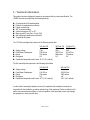
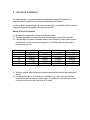
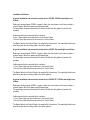
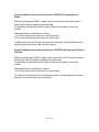
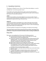
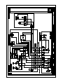
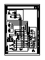
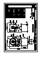
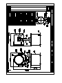
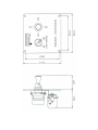
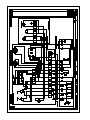
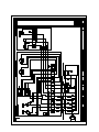
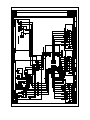
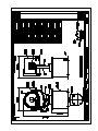
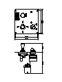
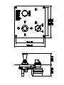
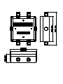
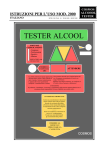
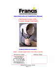
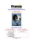
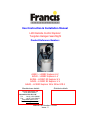
User Instruction & Installation Manual L230 Remote Control Explorer Tungsten Halogen Searchlight Product Reference Number: A2523 – L230RC Explorer H.V A2522 - L230RC Explorer L.V A2496 – L230RC RF Explorer H.V A2505 – L230RC RF Explorer L.V A2643 – L230RC Explorer 240v 300w GY9.5 Manufacturers details: Distributor details: Francis Searchlights Ltd Union Road, Bolton Lancashire, BL2 2HJ, UK Tel: +44 (0) 1204 558960 Fax: +44 (0) 1204 558979 http://www.francis.co.uk E-mail: [email protected] Manual Part Number: C23289 Issue : 5 CONTENTS 1 - Introduction 2 - Safety Precautions 3 - Technical Information 4 - Unpacking and Installation Instructions 5 - Electrical Installation 6 - Operating Instructions 7 - Fault Finding 8 - Maintenance and Servicing 9 - Wiring Diagram & General Assembly 10 - Spare Parts List 1 - Introduction It is imperative that this manual is read carefully and understood before installing your equipment. For your future reference please keep this manual in a safe place. Thank you for specifying a product from the Francis Searchlights range. All Francis products are designed to give complete customer satisfaction and are manufactured to the highest engineering standards in order to ensure optimum performance and service life. The Francis LITE range combines features proven over many years service in the most hazardous conditions in both marine and land installations. In order to prolong the life and performance of your product, we recommend that you only specify Francis Searchlights spare parts. This will also ensure that any warranties on your equipment will not be invalidated. Information on spares ordering and parts is provided in this manual. Should you ever need to contact Francis Searchlights Ltd. regarding your equipment, please quote the Product Serial Number at all times. Back To Top 2 - Safety Precautions The following instructions must be adhered to, in order to ensure a safe working environment and the safety of the user. Note: When unpacking or manoeuvring the searchlight into its fixing position, suitable lifting points must be used in order to prevent damage to the equipment or personal injury. Prevent rain, snow, condensation and water droplets from contacting the lamp as this may cause bulb failure and possible shattering; Quartz halogen bulbs run with a high internal pressure in excess of atmospheric. Whilst the construction is inherently strong, there is a slight risk of the bulb shattering; Never look directly into an illuminated searchlight as this may cause severe damage to eyesight. If it is necessary to inspect a lamp whilst in operation, always wear suitable protective goggles; Should it be necessary to examine the lamp with the front bezel removed, always use a protective shield and wear goggles to ensure a safe working environment; Never attempt to clean a lamp whilst in use; Searchlights get hot. Never touch the unit when lit and always allow 15 to 20 minutes for cooling down after turning the searchlight off; Never place anything on or cover the searchlight when in use; Ensure the lamp has cooled sufficiently before removal; If undue force appears necessary to remove the lamp, the equipment should be inspected by a competent person or contact the manufacturer; When breaking a lamp for disposal, care must be taken to ensure the glass fragments are safely contained. This operation must be performed out of doors in free air. In all circumstances refer to the lamp manufacturers instructions packed with the lamp; Due to the vast range of lamps available it may appear possible that more powerful lamps can be used in the equipment than for which it was designed. Even when the unit will physically accept a higher wattage or voltage lamp, this substitution is not recommended and is dangerous. This action will also void any warranties on the equipment. Always refer to the lamp manufacturers technical data when dealing with lamps. Back To Top 3 - Technical Information This product has been designed to operate in accordance with the product specification. The L230RC Explorer searchlight has the following features: Constructed from 304 stainless steel; Parabolic formed aluminium reflector; Powder coated finish; 365° horizontal rotation; Vertical movement +25° to -25°; Motor speed 20°/sec (Pan). ,5°/sec (Tilt); Self regulating internal heater.(Optional); Toughened front glass; The 115/240v searchlight also performs to the following optical data: 300 Watt T/H Supply voltage Peak Beam Candlepower Range Divergence Operational temperature with heater 120v 832,000 lux 912 metres 4.8° -50°C (-20° without) 300 Watt T/H 75 Hours Life 240v 790,000 lux 888 metres 4.8° 300 Watt T/H 2000 Hours Life 240v 521,400 lux 722 metres 5.4° The 24v searchlight also performs to the following optical data: 150 Watt T/H Supply voltage 24v Peak Beam Candlepower 614,000 lux Range 784 metres Divergence 2.8° Operational temperature with heater -50°C (-20° without) 250 Watt T/H 24v 1200,000 lux 1095 metres 3.8° -50°C (-20° without) In order that the searchlight operates correctly it is imperative that competent personnel are responsible for the installation, operation and servicing of this equipment. Failure to adhere to this advice may cause premature failure or incorrect operation of the searchlight, which may damage the equipment or cause personal injury. Back To Top 4 - Unpacking and Installation Instructions The following instructions should be read and fully understood prior to installing the equipment to ensure that the correct procedures are followed and all safety precautions are observed. Note: If the equipment has been in storage for a considerable amount of time, it is advisable to conduct a routine maintenance check on all parts before installation. Safety Precautions This equipment should not be connected to an electrical supply before being installed. Installation procedures should be adhered to in order to ensure a safe working environment and reduce the risk of damage or personal injury. Preparing the Mounting Position Mark out and drill the fixing holes through the deck (refer to drawing C23290). If anti-vibration mounts are to be fitted, the fixing holes for the mounts should also be marked out and drilled. Prior to manoeuvring the searchlight into its’ fixing position, the AV mounts should be fitted to the base. When in the desired position, bolt the searchlight firmly down. On and uneven surface it may be necessary to use a suitable sealant such as silicone, in order to ensure a weatherproofed joint. Back To Top 5 - Electrical Installation For safety purposes, only competent personnel should perform the electrical installation. All equipment should be installed to current Electrical Regulations and Standards. In order to obtain the maximum light output from the searchlight, it is essential that the full operating voltage of the lamp fitted be applied to the lampholder contacts. Method of Electrical Connection 1) Disconnect the supply before working on the electrical system; 2) The searchlight must be connected to a fused electrical supply, using suitably sized cable; 3) If the searchlight is located a considerable distance from the supply, provision must be made in the cable size in order to overcome the voltage drop. The following table should be used for indication purposes only: Searchlight Cable Size (mm²) 1.5 2.5 4.0 6.0 10.0 24v 150w Distance Max 24v 250w Distance Max 120v 300w Distance Max 230v 300w Distance Max 5 MTRS 8 MTRS 13 MTRS 20 MTRS 34 MTRS 3 MTRS 5 MTRS 8 MTRS 12 MTRS 20 MTRS 13 MTRS 21 MTRS 32 MTRS 50 MTRS 84 MTRS 24 MTRS 39 MTRS 62 MTRS 96 MTRS 161 MTRS 4) Whenever possible cable terminations should be made below deck and with approved terminal devices; 5) If a spare auxiliary fuse or circuit breaker is not available, one of the correct type and rating should be fitted and connected to a positive supply. It is advisable to locate a bus bar or main connection and avoid any direct connection to the supply; Installation Guidelines A typical installation and connection routine for the L230RC 115/240v searchlight is as follows: Referring to wiring diagram C23285, a supply is fed to the control panel, which then provides a common feed to the motor gearbox and the searchlight. The searchlight has been pre-wired with 3 meters of cable from the gearbox to junction box provided. Cables required to be connected by the customer: 4 core 1.5mm cable from the junction box to the Control Panel. 12 core 0.5mm cable from the junction box to the Control Panel. The Mains cable to the Control Panel to be supplied by the customer. The searchlight head is prewired along with the connecting cable to the motor gearbox. A typical installation and connection routine for the L230RC 24v searchlight is as follows: Referring to wiring diagram C23279, a supply is fed to the control panel, which then provides a common feed to the motor gearbox and the searchlight. The searchlight has been pre-wired with 3 meters of cable from the gearbox to junction box provided. Cables required to be connected by the customer: 4 core 1.5mm cable from the junction box to the Control Panel. 12 core 0.5mm cable from the junction box to the Control Panel. The Mains cable to the Control Panel to be supplied by the customer. The searchlight head is prewired along with the connecting cable to the motor gearbox. A typical installation and connection routine for the L230RC RF 115/240v searchlight is as follows: Referring to wiring diagram C23293, a supply is fed to the control panel, which then provides a common feed to the motor gearbox and the searchlight. The searchlight has been pre-wired with 3 meters of cable from the gearbox to junction box provided. Cables required to be connected by the customer: 4 core 1.5mm cable from the junction box to the Control Panel. 12 core 0.5mm cable from the junction box to the Control Panel. The Mains cable to the Control Panel to be supplied by the customer. The searchlight head is prewired along with the connecting cable to the motor gearbox. A typical installation and connection routine for the L230RC RF 24v searchlight is as follows: Referring to wiring diagram C23291, a supply is fed to the control panel, which then provides a common feed to the motor gearbox and the searchlight. The searchlight has been pre-wired with 3 meters of cable from the gearbox to junction box provided. Cables required to be connected by the customer: 4 core 1.5mm cable from the junction box to the Control Panel. 12 core 0.5mm cable from the junction box to the Control Panel. The Mains cable to the Control Panel to be supplied by the customer. The searchlight head is prewired along with the connecting cable to the motor gearbox. A typical installation and connection routine for the L300RC RF with Slave Joystick Panels is as follows: Referring to wiring diagram C24754, a supply is fed to the junction box PCB, which then provides a common feed to the motor gearbox, searchlight and control panels. The searchlight has been pre-wired with 3 metres of cable from the gearbox to junction box provided. Cables required to be connected by the customer: 12 core 0.5mm cable from the junction box to the control panels. The mains cable to the junction box to be supplied by customer. The searchlight head is pre-wired along with the connecting cable to the motor gearbox. Back To Top 6 - Operating Instructions This equipment is designed for use out of doors, in free air. Never place anything on, or cover the searchlight when in use as this may present a hazard. The searchlight can be remotely positioned via the joystick control panel, with the facility for movement up, down, left and right. When in the desired position the joystick should be released so that it returns to its’ home position, dead centre. L230RC The beam of the searchlight can be internally adjusted to give a variety of spreads. Using the focussing handle situated underneath the lampholder base. The lampholder can be moved into the desired position, towards the front for spot or the rear for flood. L230RC RF The beam of the searchlight can be adjusted to give a variety of beam types. Using the yellow remote focus button on the joystick panel, the desired beam can be achieved for any particular application. The beam will move continuously through ‘spot’ to ‘flood’. In order to fix the beam type; simply release the button at the desired position. The heaters specified on this equipment are self-regulating, so will adjust the heat accordingly. This product should not be used for any purpose other than for which it was designed. Any modifications to the product should not be undertaken without consulting the manufacturer. Setting to Work Safe service in use necessitates the strict observance of the following precautions. Any article fabricated from quartz or glass is inherently fragile and care should therefore be taken, at all times, when handling lamps; Eye protection must be worn when handling lamps that have been removed from their packaging materials. The protective jacket should not be removed from the lamp for safety reasons, as there is a remote possibility of the lamp shattering violently, especially if it is subjected to mechanical shock or vibration; Always isolate the equipment from the supply before inserting a lamp; Before inserting the lamp ensure that all contacts are clean. Contacts must be renewed at the slightest sign of corrosion. Sanding or filing down corroded areas is not recommended as this will only make the conducting surface between the pin and lampholder smaller, thus causing the lamp to overheat; Do not twist or bend the fused quartz bulb when fitting the lamp as mechanical stresses MUST be avoided; The lamp must be capable of unimpeded expansion when it warms up to operating temperature. Mechanical forces must not be applied to the fused quartz bulb; Before the protective jacket is removed, suitable protection must be worn i.e face mask and gloves with wrist protection; Never touch the quartz bulb with bare hands, as fingerprints will make the glass cloudy and cause a severe loss of light. This may also cause recrystallisation and thus weaken the bulb material. Should the bulb be inadvertently touched, remove fingerprints with methylated spirit and a clean, soft paper towel. The bulb should then be wiped with distilled water. NOTE: ALWAYS WEAR MASK AND GLOVES DURING CLEANING); In all circumstances the lamp manufacturers data should be referred to when dealing with lamps. When fitting the lamp: - Always isolate the equipment from the supply when inserting a lamp; Ensure the circuit is suitably fused; Ensure the lamp is of the correct power rating and type; Check lampholder is in good condition. If the contacts show any sign of corrosion, replace the lampholder; Check the lampholder is in a good dry condition. Never allow water to collect in the lamp fitting or come into contact with the lamp. To fit the lamp: - Remove the front bezel assembly by operating the safety catch and lifting the catch body ; For easier access the light shield/spill ring may be removed by undoing the fasteners; Cut open one end of the protective sleeve surrounding the lamp; Using the sleeve to prevent the fingers coming into contact with the lamp, position the two pins above the holes in the lampholder; Gently push the lamp into the lampholder and remove the protective sleeve; Replace the light shield/spill ring and front bezel assembly, ensuring the safety catch is engaged. Testing Upon correct installation and connection to an electrical supply, the equipment can be tested in order to ensure its’ correct performance. A competent person with some knowledge of electrical equipment must carry out this work. Equipment required: Multi-meter with leads Ammeter Using the equation P=VI, the approximate power output of the equipment can be calculated in the following way: - Using the multi-meter, take a voltage reading; Using the ammeter, take an amps reading from the live cable to the lamp; Multiply these figures together to give an approximate wattage (Power output). For example: Using a 24v 150w Tungsten halogen lamp: Voltage reading = 24v; Amps reading = 6 amps Therefore, Wattage = 24 x 6 = 144 watts Back To Top 7- Fault Finding All fault finding must be conducted by a competent person or qualified Electrical Engineer. Failure of Lamp to light Causes: 1) Power not supplied; 2) Fuse blown; 3) Failed lamp Remedy: 1) Check voltage at supply. If supply is not present the fault is at the customer supply. If power is present, see remedy 2; 2) Check fuse for visual failure. If none noticeable check fuse for continuity using a multi-meter. If fuse found to be faulty, replace with new part and test equipment again for correct working order. If found to be working correctly see remedy 3; 3) Firstly, check supply at lampholder connecting block (within searchlight barrel). If supply is present, disconnect unit from power supply before removing the lamp. If noticeable damage to filament is present, the lamp will have failed. The lamp can also be checked for continuity using a multi-meter. Replace lamp ensuring all precautions and instructions previously outlined in this manual are adhered to. Back To Top 8 - Maintenance and Servicing In order to prolong the service life and performance of your searchlight, the following maintenance guidelines are recommended: Maintenance checks should be conducted before very voyage or at least every three months; Before checking, disconnect the equipment from the supply; Visually inspect the condition of the equipment; Any major or minor structural damage should be rectified immediately in order to reduce sympathetic wear; After inspection it may be necessary to clean the inside of the searchlight. The following procedure should be adhered to: Remove the front bezel; Clean the front glass inside and out using a proprietary glass cleaner or metal polish; Clean the reflector if required; Ensure that the lampholder is free from corrosion or other damage; It is advisable to check all seals and gaskets for signs of degradation. Renew if necessary; The searchlight is fitted with a breather unit. This ensures a steady airflow in order to prevent any vacuum forming within the barrel. Upon completing all maintenance requirements the searchlight should be tested for full working order (approximately 20 minutes). If in any doubt as to the correct servicing procedures to adopt please contact your distributor/agent or the manufacturer who will be able to advise the best course of action for your product. Back To Top 9 - Wiring Diagram & General Assembly Drawing Number Description L230RC C23285 115/240v Explorer RC Wiring Diagram C23279 24v Explorer RC Wiring Diagram A2523 L230RC Explorer 24/115/240v G.A. A2643 L230RC Explorer 240v 300w GY9.5 G.A. C22821 Control Panel H.V C23011 Control Panel L.V L230RC RF C23293 H.V Explorer RC Wiring Diagram C23291 L.V Explorer RC Wiring Diagram C24754 H.V. & L.V. RC Wiring Diagram with Slaves A2496 L230RC RF Explorer H.V & L.V G.A. C22848 Control Panel H.V C22431 Control Panel L.V C23603 Junction Box Assembly 10 - Spare Parts List The following spare parts can be ordered directly from the manufacturer: Part Number Description Searchlight Spares D14795 D4695 D9851 D16883 D16841 D23795 C16878-00 C20262-00 C14143-00 C14142-00 C14444-00 C21140-00 C21141-00 C21120-00 C16410-00 C22268-01 C16761-00 C20281-00 24v 150w 300HRS GX6.35 Tungsten Halogen Lamp 24v 250w 2000HRS GX6.35 Tungsten Halogen Lamp 24v 250w 300HRS GX6.35 Tungsten Halogen Lamp 120v 300w 75HRS GX6.35 Tungsten Halogen Lamp 230v 300w 50HRS GX6.35 Tungsten Halogen Lamp 230v 300w 2000 HRS GY9.5 Tungsten Halogen Lamp Lampholder GX6.35 Lampholder GY9.5 Switch 10A - On/Off Switch – Focus Joystick Front Glass Front Glass Gasket Reflector Motor - Remote Focus Breather Assy A.V. Mount Bellows Motor Gearbox Spares C23259-01 C23267-01 C22380-00 C22382-00 C23234-00 C23530-00 Pan Motor Assy Tilt Motor Assy Microswitch no leaver Microswitch with leaver Pedestal Sealing Gasket P.S.U In order to prolong the life and performance of your product, we recommend that you only specify Francis Searchlights spare parts. This will ensure that any warranties on your equipment will not be invalidated. When ordering spare parts please contact the Sales Department at Francis Searchlights Limited. Please quote searchlight model and serial number at all times. This will enable a fast response to your spares’ requirements. Back To Top