1
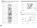
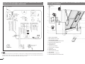
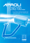
10-2005
CHECKING AND MAINTENANCE:
To achieve an optimum performance and longer life of the equipment and in observance of the safety regulations, it is recommended that inspections
and proper maintenance are made by qualified technicians to the whole installation ie, both the mechanical and electronic parts, as well as wiring:
- Mechanical parts: maintenance every 6 months approx.
- Eletronic apparatus and safety equipment: maintenance every month.
IMPORTANT WARNING NOTES
- Before installing the equipment carry out a Risk Analysis and fit any required device in compliance with EN 12445 and EN 12453 Safety Norms.
- It is recommended to keep to the instructions here outlined. Check the specifications on the motor sticker with your mains supply.
- Dispose properly of the packaging: cardboard, nylon, polystyrene, through specializing companies.
- Should the operator be removed, do not cut the electric cable. This must be properly removed from the terminal board in the junction box.
- Switch off the mains switch before removing the junction box cover where the electric cable is terminated.
- All the system must be earthed by using the yellow/green wire, marked by its specific symbol.
- It is recommended to read the regulations, suggestions and remarks quoted in the booklet “Safety Norms”.
®
Made in Italy
The growth of MECCANICA FADINI has always been based on the development of guaranteed products thanks to our “TOTAL QUALITY
CONTROL” system which ensures constant quality standards, updated knowledge of the European Standards and compliance with
their requirements, in view of an ever increasing process of improvement.
The “CE” mark certifies that the operator conforms to the essential requirements of the European Directive art. 10 EEC 73/23, in relation
to the manufacturer’s declaration for the supplied items, in compliance with the body of the regulations ISO 9000= UNI EN 29000.
Automation in conformity to EN 12453, EN 12445 safety standards.
EUROPEAN MARK CERTIFYING CONFORMITY
TO THE ESSENTIAL REQUIREMENTS OF THE
STANDARDS 98/37/EC
• DECLARATION OF CONFORMITY
• SAFETY NORMS
• EN 12453, EN 12445 STANDARDS
• CEI EN 60204-1 STANDARDS
• WARRANTY CERTIFICATE ON THE CUSTOMER’S REQUEST
®
Distributor’s box
s.n.c.
AUTOMATIC GATE MANUFACTURERS
The manufacturers reserve the right to change the products without any previous
notice and are not liable for possible damages to people and properties.
Via Mantova, 177/A - 37053 Cerea (Verona) Italy - Tel. +39 0442 330422 r.a. - Fax +39 0442 331054 - e-mail: [email protected] - www.fadini.net
GB
INSTALLATION MANUAL
®
APROLI 480 OIL-HYDRAULIC OPERATOR FOR GARAGE DOORS
INSTRUCTIONS FOR THE INSTALLATION OF APROLI 480 TO A GARAGE DOOR WITH COUNTERWEIGHTS
SECTION VIEW OF THE OIL-HYDRAULIC OPERATOR WITH LAMP AND COVER
WEATHER STRIP
UPPER SECTION
SUPPORT
DOOR HANDLE
DOOR
UPPER EDGE
WALL FRAME
DOOR JAMB
LAMP REFLECTOR
COUNTERWEIGHT WHEEL
GARAGE DOOR
LIGHT DIFFUSION
COVER
230 V-25 W LAMP
SCREW SEAT FOR FIXING THE
COVER/UPPER SECTION
GUIDE ARM
LATERAL SUPPORT
TELESCOPIC ARM
ELECTRIC TERMINAL COVER
COUNTERWEIGHT
WEATHER STRIP
ELECTRIC TERMINALS
OIL CONTAINER
“S”
APROLI 480
COUNTERWEIGHT CASE
WITH COVER
AIR BLEED SCREW
ELECTRIC MOTOR
TOP END CAP
WEATHER STRIP
BOTTOM DOOR WHEEL
O.33 HP ELECTRIC MOTOR
FADINI OIL
A 15 BY AGIP
100x5 mm REINFORCEMENT
PLATE TO BE FIXED TO
THE DOOR FRAME
FIXING BRACKET
“M”
OIL RESERVOIR
PIC. 2
HYDRAULIC LOBE PUMP
FADINI OIL A 15 BY AGIP
No change to the existing door is required for the installation of this operator. Automatic or semi-automatic operations. Hand operation
can be made possible by releasing the system through the lever “B” both from inside or outside the building. (Pic.1)
TWO-WAY
LOCKING VALVE
PRESSURE VALVE
ASSEMBLY
“B”
“C”–“A”
MANUAL RELEASE LEVER
TWO-WAY LOCKING
VALVE ASSEMBLY
ESSENTIAL COMPONENTS FOR THE APPLICATION OF THE OPERATOR ON TO A GARAGE DOOR HAVING
COUNTERWEIGHT (PIC.3)
PISTON SLEEVE
TERMINAL
BOARD
COVER
FADINI OIL A 15 BY AGIP
GEAR BOX
HOUSING
TOOTHED SHAFT
SPACER BEARING/
GEAR TEETH
COVER
1st PISTON WITH STEEL INSERT
TELESCOPIC ARM
“S”
TELESCOPIC
ARM
SHAFT SUPPORT
RACK
AIR BLEED
TRANSMISSION BAR
WITH SHAFT FITTING
SLEEVE (SQUARE
HOLE) WELDED TO IT
2nd PISTON WITH STEEL INSERT
MAX. PRESSURE SAFETY VALVE
OPEN. RED
“A”
MAX. PRESSURE SAFETY VALVE
CLOSE. GREEN
“C”
TRANSMISSION BAR
LATERAL SUPPORT
SCREW SEAT FOR FIXING
THE COVER/BOTTOM END
BOTTOM SECTION
PIC. 1
2
FADINI OIL A 15 BY AGIP
CYLINDER END CAP
“M” FIXING
BRACKET
PIC. 3
3
It is recommended to follow the drawings in this manual to install APROLI 480 on to garage doors in order to automate them.
The operator is designed for the installation in the centre of the existing door by means of a bracket “M” that is fixed to the door with
screws. Pic.4
40
40
TELESCOPIC ARM OVERLAPPING THE DOOR ARM WHEN
THERE IS NO SPACE BETWEEN ARM AND COUNTERWEIGHT
15
5°
WALL FRAME
DOOR JAMB
DOOR
FRAME
FIXING
ABOVE
THE ARM
PIVOT
EXISTING
GUIDE ARM
40
2˙500
DOOR
FIXING
FIXING ON TO THE
GUIDE ARM
GUIDE ARM OF THE
EXISTING DOOR
“M”
COUNTERWEIGHT
CASE AND ROLLER
GUIDE TUBE
PERPENDICULARLY
FITTED
BRACKET
“M”
TELESCOPIC ARM
OVERLAPPING THE
DOOR ARM WHEN
THERE IS NO SPACE
BETWEEN ARM AND
COUNTERWEIGHT
OPERATOR IN THE
OPEN POSITION
10
FIXING ON TO
THE GUIDE ARM
3˙0
00
REINFORCEMENT
PLATE 100x5 mm
PIC. 4
PIC. 6
Should the upper and lower fixing ends of the bracket “M” not coincide with the upper and lower edges of the door, it is recommended
to rivet, screw or spot weld an iron reinforcement plate (100 mm - 5 mm thickness) vertically across the door so to connect the top and
bottom edges of the door as shown in pic. 4
Once the bracket and the operator have been fixed to the door, proceed to temporarily fix the two telescopic arms to the torsion shaft,
considering that the shaft must be allowed to rotate 5 degrees less than the end of the permitted stroke, as further explained in pic.7
TELESCOPIC ARM TO BE
PARALLEL FIXED TO THE
EXISTING DOOR ARM
15
FIXING PLATE
TO WELD
90
END OF PISTON STROKE
WHEN NO FURTHER
TURNING IS ALLOWED
90
HYDRAULIC LOCKING/
UNLOCKING LEVER
“B”
80
60
60
20
REINFORCEMENT
ROTATE IN THE ARROW
DIRECTION BY 5 mm TO GET 5°
APROLI 480
CLOSED DOOR
POSITION
100 x 5
OPEN
5
DOOR JAMB/
COUNTERWEIGHT
CASE
5 mm
PIC. 5
PIC. 7
Once the bracket “M” has been fixed, it is to be determined whether the telescopic arms are to overlap the existing door arms or be
fixed parallel to them. See pic. 5 and 6. Then proceed to weld the fixing plates as indicated by the distances in pic.5
Rotate the shaft to the end of the permitted stroke by means of pliers. Then rotate the shaft back by 5 mm. This allows more power to
the operator when it is required to close the door. Pic. 7. Please note the door must be in closed position when this operation is done.
4
5
Once satisfied that the installation is correct and smooth, remove the two torsion bars and the sliding bars in order to firmly fix them
by welding all around. Pic.9
CLOSED DOOR
FIXING PLATE
“B”
TELESCOPIC
ARM
LEVEL
IN THIS POSITION THE DOOR
MUST BE WELL BALANCED.
SHOULD IT NOT, ADD SOME
EXTRA COUNTERWEIGHT
LEVEL
FIX THE COVER
ONLY AFTER
COMPLETING THE
INSTALLATION
LATERAL
SUPPORT
LATERAL SUPPORT
PROVIDED WITH
THE EQUIPMENT
TORSION BAR
45°
PIC. 8
Fit the two telescopic arms to the torsion bars and make sure that they are perfectly perpendicular to them at the same distance from
the door. Adjust the two supports to achieve the above and put some wooden spacers to bring the lateral supports to the required
distance. A spirit level will ensure that the torsion bars are perfectly horizontal. See pic. 8. The lever «B» must be in the released position.
PIC. 10
A good test to verify how well balanced the door is in both directions, ie. lifting and lowering, is to position it 45 degrees from ground
level, as shown in picture 10. Add counterweight to improve running smoothness and balance if required.
FIXING PLATE
“S” AIR BLEED
TELESCOPIC ARM
WITH SLIDING BAR
TELESCOPIC ARM
WITH SLIDING BAR
CUT TO MEASURE
AND WELD
CUT TO MEASURE
AND WELD
LEVEL
LEVEL
MAXIMUM
PRESSURE
VALVE “OPEN”
RED IN COLOUR
“A”
MAXIMUM
PRESSURE VALVE
“CLOSE”
GREEN COLOUR
“C”
“B”
The two safety pressure valves are identified by colours: «A»
Open is red; «C» close is green. They are located in the front
of the motor/pump unit, easy to reach for setting operations in
order to meet the power requirements.Pic.11
Once the valves are set, you can fit the cover and the other
accessories. Pic.10
RELEASE LEVER
TURN IT
ANTI-CLOCKWISE
LATERAL SUPPORT
TORSION BAR
WITH SLEEVE
MORE
POWER
LESS
POWER
CIRCULAR WELDING
The setting of the safety pressure valves is to be done so to
achieve the exact amout of power required to safely operate
the door. The more you turn the screw clockwise, the more you
increase the power of the operator.
PIC. 9
Fit the two telescopic arms and the torsion bars in the correct position and make sure that they are levelled and parallel, door in the
closed position. Partially weld the torsion bars to the lifting arms and operate the door by hand. Verify that it can open fully in a quiet
and smooth way. The lever «B» in the released position. Pic.8.
6
PIC. 11
7
The electric cable which supplies power to the motor/pump is connected by means of terminals, which are located above the oil
container, next to the earth screw connection. The cable must be led along the door to the point where the telescopic arm is welded
to the bar. It is recommended that the cable is allowed to dangle free by 130 cm so that the door can go fully up to the end of the permitted
stroke.
RELEASE
LEVER
“B”
POSITION OF THE
EARTH SCREW
CONNECTION
RUBBER STOP
OPEN
RECOMMENDED STARTING POSITION
BEFORE CLOSE CYCLE
RUBBER STOP
ELPRO 6 exp
25
RUBBER STOP ON
THE OUTSIDE OF THE DOOR
CLOSE
PIC. 12
OPEN
The highest power is required to start the close cycle. Therefore it is recommended to fit rubber stops to the door. This will cushion
the door at the end of the up stroke and will keep the door inclined by 5 degrees for a better start. See Pic.12.
APROLI 480
WITH COVER
CLAMP
RELEASE
LEVER
“B”
LOCKABLE
HATCH DOOR
ELECTRIC CABLE TO DANGLE
FREE LENGTH 1.30 METRES
PIC. 14
RELEASE CORD
COURTESY
LIGHT
DOOR SECTION
To release Aproli 480 for hand operations it is available
a device as described above, on request. Turn the key
sharply; this will pull the cord and the lever open. As
an option you can fit the door with a service hatch.
Pic.13
EXTRA CAPACITOR IN CASE OF
POWER SHORTAGE OR TO IMPROVE
THE POWER OF THE OPERATOR
WHEN HEAVY DOORS ARE INVOLVED
HATCH
RELEASE LEVER
DOOR FROM OUTSIDE
TO REVERSE THE DIRECTION OF THE
SHAFT ROTATION SWOP WIRES ROUND
No. 10 AND No. 12 DO NOT CHANGE No.11
10 11 12 13 14
ELPRO 6 exp
PIC. 13
PIC. 15
There are two solutions to get access to the operator release lever for hand operations of the door. Either a lock is fitted at a suitable
distance from the release lever, to which it is connected by a steel flexible cord as in Pic.13; or a 12 cm x 12 cm lockable hatch is
provided and fitted to allow a hand to pass from outside to inside and release the lever «B».
It is essential to make sure that the shaft rotates in the required direction during the first running test. Should it rotate in the opposite
direction, change wire No. 10 with No. 12. Pic. 15
8
9
ELECTRICAL WIRING DIAGRAM OF THE OIL-HYDRAULIC GARAGE DOOR OPERATOR
APROLI 480 TO THE ELECTRONIC CONTROL PANEL
GARAGE DOOR OPERATOR COMPLETE WITH ALL THE RECOMMENDED ACCESSORIES
FOR A GOOD PERFORMANCE
230 VOLTS
MAINS SUPPLY
1
BIRIO A8 AERIAL
2
TRANSFORMER
230
0
I.T.F.
9
3
4
6
5
7
8
9
1
R2
R1
ANT.
N.A.
C N.C
.
MOTOR RUN
OPEN & CLOSE TIME
R2
GND
FUSE
630 mA
1° CHANNEL
2
R1
24 V OUTPUT
1
3
0
24
meth
8VA
RADIO CONTROL
PLUG-IN CARD SUPPORT
ASTR
INNESO 43
TO
0
PLUG-IN
ASTRO 43
LED ON VOLTAGE
SUPPLIED
4
10
CAPACITOR
DIP-SWITCH
ON
ASTRO 43/2 RADIO RECEIVER
PLUG-IN PC BOARD
1
DWELL TIME
FUSES
5A
12,5 µF
2
1 2 3 4 5 6 7 8 9
11
5
12
10 11 12 13 14 15 16 17 18
COMUNE
M1
230 V SINGLE-PHASE
SUPPLY VOLTAGE
230 V - 25 W MAX.
FLASHING LAMP
230 V - 25 W MAX.
COURTESY LIGHT
EARTH
SINGLE-PHASE MAX. 400W
ELECTRIC MOTOR
MAX. PERMITTED
LOAD:
1 PAIR PHOTOCELLS
1 RADIO RECEIVER
3
24 V OUTPUT A.C.
LIMIT SWITCH. OPEN. N.C.
LIMIT SWITCH. CLOSE. N.C.
BUTTON ON
THE COVER LID
LIMIT SWITCH. COMMON
N.O. CONTACT. OPEN SWITCH
STOP CLOSE AND RADIO
N.C. CONTACT. PHOTOCELLS
AND SAFETY EDGE
- COURTESY LIGHT FOR TWO MINUTES. ON - FLASHING LAMP. OFF
- AUTOMATIC RE-CLOSING. ON - SEMI-AUTOMATIC.OFF
Should more pairs of photocells be required than the
recommended quantity, fit an auxiliary transformer outside
the control box.
NOTE WELL: THIS PANEL IS TESTED TO OPERATE GATES
ONLY THROUGH FADINI ACCESSORIES. NO GUARANTEE
FOR ACCESSORIES OF OTHER MAKE OR SPECIAL
APPLICATIONS.
OFF
6
en
op
13
7
8
4
ALL OPERATIONS
OPEN, STOP & CLOSE
RADIO CONTACT
6 exp
PC BOARD DRWG. 1795
1 - 0.03 Amp. CIRCUIT BREAKER
14
2 - MIRI 4 FLASHING LIGHT 25 Watts
FITTED WITH BIRIO A8 AERIAL
3 - PLUG-IN RADIO RECEIVER CARD ASTRO 43 SAW
4 - ELECTRONIC CONTROL BOX Elpro 6 exp
OPEN
CLOSE
IT IS ILLUMINATED WHEN
VOLTAGE IS SUPPLIED
COMMON
1 2 3 4
5 - START PUSH BUTTON
STOP
ELECTRICAL CONNECTIONS
KEYSWITCH PRIT 19
KEYSWITCH
PRIT 19
6 - KEYSWITCH PRIT 19
7 - SAFETY EDGE. LOW PROFILE
8 - PHOTOCELL TRIFO 11. RECEIVER
9 - 25 Watt LAMP
10 - OPERATOR APROLI 480
11 - COVER TO PROTECT THE VALVES
PIC. 16
12 - FIXING BRACKET
13 - PHOTOCELL TRIFO 11. PROJECTOR
All the electrical connections to the control panel are to be made as per – Drawing 1795 – Elpro 6 exp having the following features:
terminals for the keyswitch open-stop-close, photocells, safety edge, courtesy light, remote control to terminals 3 & 4 where the first
pulse opens the door, the second stops it and the third re-cycles to open or close.
10
14 - RADIO TRANSMITTER ASTRO 43 TWO BUTTONS
PIC. 17
11
APPLICATION OF APROLI 480 ON TO A DOOR WITH UPPER TRACK, FULLY INDOOR
SPECIAL GARAGE DOORS
UPPER FIXING BY THE SIDE
OF THE DOOR SLIDING GUIDE
SAFETY SWITCH
WARNING LAMP
ON STARTING
WITH RADIO AERIAL
UPPER GUIDE
2˙500
13 CEI
400
SINGLE-PHASE
IN TH
E MI
DDLE
OF
COUNTERWEIGHT
1.30 m ELECTRIC CABLE
TO DANGLE FREE
UPPER ROLLER
FOR HORIZONTAL
UPPER TRACK
THE
DOO
R
COUNTERWEIGHT
4˙000
REINFORCEMENT PLATE
100x5 mm
REINFORCEMENT PLATE
100 x 5 mm
PIC. 18
When very large doors are involved with a service door in the middle, it is recommended to install two operators Aproli 480 on to the
door sides without connecting the shaft inner ends. Fixing dimensions and measurements are as explained before in the previous
application drawings. It is also recommended to fit the service door with a safety microswitch as shown in pic.18
When two operators are required for one door, it is recommended to install the control panel “Elpro 13 CEI” and one pair of photocells
Trifo 11. These are to be fixed on to the “counterweight case” 40 cm from ground level.
LOWER ROLLER SLIDING IN
THE LATERAL PERPENDICULAR
CASING
WALL FRAME
PIC. 20
For the installation of Aproli 480 on to garage doors with upper track follow the same instructions as explained before; the shaft ie. the
torsion fulcrum must coincide with the centre line of the door, right in the middle between upper and lower guide rollers. See Pic. 20
APPLICATION OF APROLI 480 ON A JACK-KNIFE DOOR
UPPER HINGES
UNSCREW BY ONE
TURN TO BLEED
AIR OUT OF THE
OIL TANK
“S”
80 / 100 mm
6 exp
STEP BY STEP
2˙500
CENTER
HINGES
ELECTRIC CABLE
LOOP LENGTH 1.30 m
IMPORTANT AFTER
INSTALLATION
SLIDING GUIDE
FOR ROLLER
REINFORCEMENT PLATE
100 x 5 mm
APROLI 480
3˙0
00
UNDO BY ONE TURN
“S”
OIL FADINI A 15 BY AGIP
STICKER FITTED TO THE OIL TANK
ROLLER WITH
SLIDING GUIDE
PIC. 19
For jack-knife doors, the same instructions apply as for single-panel doors as explained in the previous pages. Only please note that
with articulated doors as the above type, it is recommended to fix the operator so that the shaft and the torsion bars are 80-100 mm
below the door hinge centre line. Pic.19
12
PIC. 21
Please note, once Aproli 480 has been fixed, unscrew the air bleed screw by one turn. This screw is fitted on the cap of the oil container,
where the voltage supplying cable is led to the motor. Pic.21 Should the operator «Aproli 480» be removed for maintenance or repairing
tighten the screw «S» to prevent oil from coming out during handling.
13
UNSCREW
OIL-HYDRAULIC OPERATOR FOR GARAGE DOORS WITH COUNTERWEIGHTS
APROLI 480
TECHNICAL SPECIFICATIONS APROLI 480
1
FIXING
BRACKET
“M”
®
s.n.c.
APROLI 480
Via Mantova, 177/A - 37053 Cerea (VR) Italy - Tel. 0442 330422 r.a. - Fax 0442 331054
2
1
DOOR OPERATOR
LINEAR DESIGN
2
3
4
MOTOR
APROLI 480
3
ELECTRIC
TERMINAL
OUTPUT
91
2 PHASE
W (absor.)
330
HP (to use)
0.33
VOLTS
230
A
1.8
Rev/min.
1˙350
Hz
50
Nm
392.4
µF
12.5
Protection Standards IP 55
Max. working pressure 4 MPa (40 Bar)
4
LAMP AND
LAMP REFLECTOR
OIL FADINI A15 BY AGIP
MADE IN ITALY
5
LAMP
REFLECTOR
DATA STICKER
ELECTRIC MOTOR
PROTECTION
COVER
5
LIGHT
DIFFUSION
TOP
COVER
7
BOTTOM
COVER
“A”
20
1˙610
“E”
“C”
600
6
6
x2
PRESSURE SWITCH
0
35
35
86
ELECTRIC CABLE
LAMP
ELECTRIC MOTOR
VOLTAGE SUPPLY
CABLE
ELECTRIC CABLE
PRESSURE SWITCH
785
180
86
SAFETY EDGE
WITH PRESSURE
SWITCH
PIC. 22
121
NEVER CUT THE ELECTRIC CABLES
7
- It is most important that the electric cables are removed from their terminals by loosening the fastening screws. Never cut the electric
cables. Also make sure that the 230 V mains switch is off before removing the cables. See page 11 pic. 17.
- Only by keeping to these fitting instructions a reliable installation and correct performance of the equipment can be achieved.
The installation is fully under the responsibility of the installation agent, even if only Fadini products have been used as indicated in
this booklet. It is advisable that the system is installed in full compliance with these instructions and in observance of the existing laws
for automatic gate equipment.
- The information, specifications and drawings contained herein are subject to any change that the manufacturer considers as needed.
PIC. 23
OIL-HYDRAULIC PUMP
ELECTRIC MOTOR
Pump flow rate .....................................................................1.10 l/min.
Working pressure ........................................................2 MPa (20 bar)
Maximum pressure......................................................4 MPa (40 bar)
Working temperature......................................................-20°C +80°C
Opening time...................................................................................18 s
Recommended door size...............................................................7 m2
Shaft rotation........................................................................max. 205°
Hydraulic oil.....................................................oil Fadini A15 by Agip
Static weight of operator........................................................10.5 Kg
Weight of Aproli 480 with accessories....................................24 Kg
Max. torque.............................................................................392.4 Nm
Max. gate weight........................................................................150 Kg
Power output...............................................................0.24 KW (0.33 HP)
Supply voltage ..................................................................................230 V
Frequency..........................................................................................50 Hz
Absorbed power ............................................................................330 W
Absorbed current.............................................................................1.8 A
Capacitor........................................................................................12.5 µF
Motor revolution...................................................................1˙350 r.p.m.
IP Protection Standard ..................................................................IP 55
Motor rated torque.......................................................................1.3 Nm
Lamp .....................................................................................230 V - 25 W
Intermittent service .............................................................................S 3
PERFORMANCE
Duty cycle.....................................................................................................................................18 sec. Opening – 30 sec. Dwell – 18 sec. Closing
Time of one complete cycle .................................................................................................................................................................................66 sec.
Complete cycles.............................................................................................................................................................................................No. 47/hour
Annual cycles - 8 hours’service per day....................................................................................................................................................No.159˙000
14
15
10-2005
CHECKING AND MAINTENANCE:
To achieve an optimum performance and longer life of the equipment and in observance of the safety regulations, it is recommended that inspections
and proper maintenance are made by qualified technicians to the whole installation ie, both the mechanical and electronic parts, as well as wiring:
- Mechanical parts: maintenance every 6 months approx.
- Eletronic apparatus and safety equipment: maintenance every month.
IMPORTANT WARNING NOTES
- Before installing the equipment carry out a Risk Analysis and fit any required device in compliance with EN 12445 and EN 12453 Safety Norms.
- It is recommended to keep to the instructions here outlined. Check the specifications on the motor sticker with your mains supply.
- Dispose properly of the packaging: cardboard, nylon, polystyrene, through specializing companies.
- Should the operator be removed, do not cut the electric cable. This must be properly removed from the terminal board in the junction box.
- Switch off the mains switch before removing the junction box cover where the electric cable is terminated.
- All the system must be earthed by using the yellow/green wire, marked by its specific symbol.
- It is recommended to read the regulations, suggestions and remarks quoted in the booklet “Safety Norms”.
®
Made in Italy
The growth of MECCANICA FADINI has always been based on the development of guaranteed products thanks to our “TOTAL QUALITY
CONTROL” system which ensures constant quality standards, updated knowledge of the European Standards and compliance with
their requirements, in view of an ever increasing process of improvement.
The “CE” mark certifies that the operator conforms to the essential requirements of the European Directive art. 10 EEC 73/23, in relation
to the manufacturer’s declaration for the supplied items, in compliance with the body of the regulations ISO 9000= UNI EN 29000.
Automation in conformity to EN 12453, EN 12445 safety standards.
EUROPEAN MARK CERTIFYING CONFORMITY
TO THE ESSENTIAL REQUIREMENTS OF THE
STANDARDS 98/37/EC
• DECLARATION OF CONFORMITY
• SAFETY NORMS
• EN 12453, EN 12445 STANDARDS
• CEI EN 60204-1 STANDARDS
• WARRANTY CERTIFICATE ON THE CUSTOMER’S REQUEST
®
Distributor’s box
s.n.c.
AUTOMATIC GATE MANUFACTURERS
The manufacturers reserve the right to change the products without any previous
notice and are not liable for possible damages to people and properties.
Via Mantova, 177/A - 37053 Cerea (Verona) Italy - Tel. +39 0442 330422 r.a. - Fax +39 0442 331054 - e-mail: [email protected] - www.fadini.net
GB
INSTALLATION MANUAL
®