1
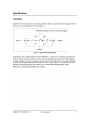
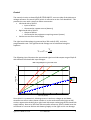
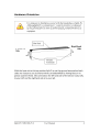
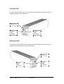
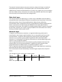
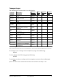
User Manual Scimar Engineering Ltd Split-Pi UDIO.60.25.L Split-Pi is manufactured under licence from 3D Instruments Ltd by Scimar Engineering Ltd and protected by patent No. GB2376357 and worldwide equivalents. MAN-UDIO6025L © Copyright 2010 Scimar Engineering Ltd The information contained herein is subject to change without notice. Scimar Engineering Ltd will not be liable for technical or editorial errors or omissions contained herein. Split-Pi UDIO.60.25.L Edition: September 2010 Document Reference: MAN-UDIO6025L Contents Specification..................................................................................................................1 Topology....................................................................................................................1 Control........................................................................................................................2 Hardware Orientation.................................................................................................4 Left-Hand Side...........................................................................................................5 Right-Hand Side.........................................................................................................5 Data Connection.........................................................................................................6 iLoop Overview.............................................................................................................7 Physical Layer............................................................................................................7 Data Link Layer..........................................................................................................8 Network Layer............................................................................................................8 Transport Layer..........................................................................................................9 Calibrated Analogue Readings.................................................................................10 Appendices..................................................................................................................13 ASCII Tables............................................................................................................13 Control The control circuitry on-board Split-Pi UDIO.60.25.L uses one side of the device as a voltage reference to control Split-Pi which is referred to as the “Left-Hand Side”. This provides the user with a simple to follow convention: • Left-hand side of Split-Pi o Input of device o Connected to a power source (battery) • Right-hand side of Split-Pi o Output of device o Connected to the equipment requiring control (motor) • Positive current from Left to Right The right-hand side voltage is governed by a 256-code (0-255), real-time, programmable ratio. The right-hand side voltage can be calculated using the equation: V rhs=V ratio V lhs 128 The following chart illustrates the operational right-hand side output range of Split-Pi with different left-hand side input voltages: RHS Voltage Output for a given Ratio Code 60 50 Voltage (Vrhs) 40 15V lhs 30V lhs 30 45V lhs 60V lhs 20 10 0 0 32 64 96 128 160 192 224 256 Ratio Code (Decimal) Since Split-Pi is symmetrical, allowing current in and out, voltage up and down, situations can occur where power transfer is in the reverse direction (right to left) such as regenerative braking by a right-hand side motor recharging the left-hand side supply battery. Due to its left-hand side controller reference, Split-Pi should never be connected in a reverse fashion with battery/supply on the right as this can damage Split-Pi UDIO.60.25.L User Manual 2 Split-Pi and any connected equipment. Table 1 shows the input and output ranges of Split-Pi in positive and negative current directions. Table 1 - Split-Pi IO Range Parameter Value Unit Conditions Positive Current (Left to Right) Left-Hand Side Input LHS Voltage min LHS Voltage max LHS Current max Right-Hand Side Output RHS Voltage min RHS Voltage max (2 x Vlhs) RHS Current max Reverse Current (Right to Left) Left-Hand Side Output LHS Voltage min (0.5 x Vrhs) LHS Voltage max LHS Current max Right-Hand Side Input RHS Voltage min RHS Voltage max RHS Current max Split-Pi UDIO.60.25.L User Manual 15 60 25 V V A 0 60 25 V V A 7.5 60 25 V V A 15 60 25 V V A LHS Voltage ≥ 30V RHS Voltage = 15V 3 Left-Hand Side The left-hand side of Split-Pi is the input side and should be connected to the DC supply equipment such as batteries. LHS Fuse Positive LHS Terminal Ground LHS Terminal Right-Hand Side The right-hand side of Split-Pi is the output side and should be connected to the equipment you wish to drive such as a DC motor. RHS Fuse Positive RHS Terminal Ground RHS Terminal Split-Pi UDIO.60.25.L User Manual 5 Data Connection Illustration 1: Female 15way D-Type Pin Signal 1 NC 2 NC 3 NC 4 NC 5 NC 6 NC 7 NC 8 NC 9 Iloop - 10 Iloop + 11 NC 12 NC 13 NC 14 NC 15 NC Table 2: Connector Pinouts Split-Pi UDIO.60.25.L User Manual 6 iLoop Overview The iLoop communication featured in Split-Pi devices is an isolated communication device that uses flow of current to send and receive data. The iLoop communication protocol can be split into standardised layers as defined by the OSI model. Physical Layer The iLoop transceiver in Split-Pi devices is a slave device that senses the flow of current to receive data and switches the current on and off to send data. A single iLoop master device must be used to supply power to the current loop. Currently there is an RS232 – iLoop adapter available that supplies current to the current loop and provides a standard RS232 interface for simple connection to a computer. Below is a simplified illustration of the master iLoop circuit with it's constant current source and isolated transmitter and receiver. The master iLoop schematic is available for Illustration 2: Simplified Master iLoop Circuit integration into an embedded control board or other system. The slave iLoop circuitry in Split-Pi devices is very similar to the master with the omission of the constant current source. Split-Pi UDIO.60.25.L User Manual 7 The physical communications uses only two wires; iLoop+ and iLoop- to send and receive data asynchronously in half duplex mode. The communication works at 19200 bits per second, sends 8 data bits in a frame, has no parity bit, has one stop bit and has no flow control. It functions in a similar way to RS232, apart from the signals are carried by current flow rather than voltage levels. Data Link Layer The iLoop protocol uses addressing in a similar way to IEEE 802.3 Ethernet MAC to communicate with several Split-Pi devices connected to the same iLoop. It has three addressing modes; Direct, Group and Broadcast. Where direct addressing communicates with a single Split-Pi device, group addressing with a group of Split-Pi device connected to the same iLoop and Broadcast with every Split-Pi device connected to that iLoop. This allows for multiple groups of Split-Pi devices connected to the same controller, for instance a group of Split-Pi's for each wheel on a vehicle, allowing individual wheel speed control. Network Layer To begin a communication transaction, an eight bit addressing mode word is transmitted on the iLoop to specify whether one or many devices will act on the communication. To perform direct addressing send the 8 bit word 0x4E (ASCII character 'N'). To perform group addressing send the 8 bit word 0x47 (ASCII character 'G') To broadcast to all devices, either Direct or Group addressing can be used as it uses a broadcast address. Then an eight bit address will be transmitted to specify the Split-Pi device/s that should further act on the communication. As default all Split-Pi devices come programmed with the address 0xFE. The broadcast address is 0xFF. Then an eight bit command word followed by variable length arguments specifying the action that the Split-Pi device/s should take. Some commands are then followed by a variable length response from a Split-Pi device. The message structure and length is shown below: 8 bits 8 bits 8 bits 8 – 32 bits 8 – 32 bits Addressing Mode Address Command Argument Response Table 3: iLoop Message Frame Split-Pi UDIO.60.25.L User Manual 8 Transport Layer The commands are summarised in the table below: Command Description Command ASCII (Hex) Address Mode Argument Bytes Response Bytes Set the node(s) voltage ratio V (0x56) B 1 code. Set the node(s) voltage ratio Hotstart1 X (0x58) B 1 code to hotstart Get the node voltage ratio GetCode O (0x4F) D 1 code GetStatus Get the node status S (0x53) D 2 Read the nodes specified ADC ReadADC I (0x49) D 1 2 channel Read a byte from a specified ReadEEPROM address within the nodes Y (0x59) D 2 1 EEPROM Go open circuit, halt voltage Halt H (0x48) B conversion. Set the node(s) group ID and SetGID J (0x4A) G 1 store in EEPROM Get the nodes currently active GetGID P (0x50) D 1 group ID Set the full node ID and store SetNID T (0x54) D 4 in EEPROM Get the currently active full GetNID W (0x57) D 4 node ID Refresh the node RefreshConf U (0x55) G configuration from EEPROM Revert to default (Factory) ResetDefault ? (0x3F) D configuration Table 4: iLoop Command Set Note 1: Hotstart requires special care and attention in its use. Please see iLoop Manual for more info. SetCode For example to set a voltage ratio of 64 (40 hex) using direct addressing: NFEV40 To set a voltage ratio of 64 using group addressing: G55V40 To read the currently set voltage ratio (interrogation only uses direct addressing): NFEO Split-Pi will then return a two-character Ascii Hex value of the code, i.e. 40 Split-Pi UDIO.60.25.L User Manual 9 Calibrated Analogue Readings Split-Pi has a built in Analogue to Digital converter that allows the user to read Voltages applied to the left and right hand sides, bi-directional Currents at either sides and the temperature of the synchronous switching bridges. The values read from the ADC are absolute values and require conversion into real values. This is achieved by reading calibration data stored in the EEPROM and running it through the equation: ADC bits −16 Actual Value 10−6 = M [ ADC−2 ×C ] where M and C are 16 bit values stored in EEPROM, ADCbits is an 8 bit value stored in EEPROM and ADC is the Analogue to Digital reading. M is the actual value of one count of the ADC in microVolts, microAmps, micro-degC. C is the zero point offset in ADC counts. Use the ReadEEPROM command 'Y' (0x59) to read the calibration data from Split-Pi's EEPROM along with the following table of addresses. The highlighted locations are the most revelant: Location Name (Hex) Location Name (Hex) Location Name (Hex) 0x00 Address 0 0x10 Volt Left M0 0x20 Current Left M0 0x01 Address 1 0x11 Volt Left M1 0x21 Current Left M1 0x02 Address 2 0x12 Volt Left C0 0x22 Current Left C0 0x03 Address 3 0x13 Volt Left C1 0x23 Current Left C1 0x04 Address Length 0x14 Volt Right M0 0x24 Current Right M0 0x05 Group Address 0x15 Volt Right M1 0x25 Current Right M1 0x06 Control State 0x16 Volt Right C0 0x26 Current Right C0 0x07 Upper Limit 0x17 Volt Right C1 0x27 Current Right C1 0x08 Lower Limit 0x18 NA 0x28 Temp Left M0 0x09 Firmware Version 0x19 NA 0x29 Temp Left M1 0x0A Calibration Version 0x1A NA 0x2A Temp Left C0 0x0B Serial Number 0 0x1B NA 0x2B Temp Left C1 0x0C Serial Number 1 0x1C NA 0x2C Temp Right M0 0x0D Serial Number 2 0x1D NA 0x2D Temp Right M1 0x0E Serial Number 3 0x1E NA 0x2E Temp Right C0 0x0F ADC Bits 0x1F Table 5: Main EEPROM Mapping NA 0x2F Temp Right C1 For example to read the ADC Bits (only accessible using direct addressing): NFEYA00F Split-Pi UDIO.60.25.L User Manual 10 Split-Pi will return two ASCII characters for example, '0C' in ASCII Hex converted to a decimal value this is 12. Each of the values stored in EEPROM are 8bits. Two bytes must be combined to get the 16bit value of M or C where M = [M1:M0] and C = [C1:C0]. Once you have the calibration data you will need to read the ADC using the ReadADC command 'I' (0x49) . The following table shows the ADC channels: Channel ASCII Hex Value Description 0 00 Voltage Left 1 01 Voltage Right 2 02 NA 3 03 NA 4 04 Current Left 5 05 Current Right 6 06 Temperature Left Bridge 07 Temperature Right Bridge 7 Table 6: ADC Channels For example to read the left hand side current (direct addressing only): NFEI04 Split-Pi will return four ASCII characters representing a 16 bit value, for example '096F' which converted to decimal is 2415. To convert this to a human readable value run this through the previous equation with the related M and C values for left hand side current. For example: Left Current M0 at location 0x20 = 0x62 Left Current M1 at location 0x21 = 0x51 therefore M = [M1:M0] = 0x5162 = 20834 (decimal) Left Current C0 at location 0x22 = 0x30 Left Current C1 at location 0x23 = 0x80 therefore C = [C1:C0] = 0x8030 = 32816 (decimal) ADC Bits at location 0x0F = 0x0C = 12 (decimal) and as in the previous example Left Current Channel 0x04 reads 0x096F = 2415 now put them into the equation: −6 ADC bits −16 Actual Value 10 = M [ ADC−2 ×C ] 12−16 Current A=20834[2415− 2 ×32816] Split-Pi UDIO.60.25.L User Manual 11 Current=20834 [2415−0.0625×32816] Current=20834 [2415−2051] Current=20834 [364] Current=7583576 A Current≈7.584 A Split-Pi UDIO.60.25.L User Manual 12 Appendices ASCII Tables Hex 30 31 32 33 34 35 36 37 38 39 Dec 48 49 50 51 52 53 54 55 56 57 ASCII 0 1 2 3 4 5 6 7 8 9 Table 7: ASCII Numbers Hex 40 41 42 43 44 45 46 47 48 49 4A 4B 4C 4D 4E 4F Dec 64 65 66 67 68 69 70 71 72 73 74 75 76 77 78 79 ASCII A B C D E F G H I J K L M N O Hex 50 51 52 53 54 55 56 57 58 59 5A 5B 5C 5D 5E 5F Dec 80 81 82 83 84 85 86 87 88 89 90 91 92 93 94 95 ASCII P Q R S T U V W X Y Z Table 8: ASCII Letters Split-Pi UDIO.60.25.L User Manual 13