1
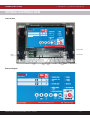
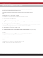
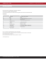
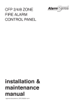
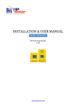
CHANNEL SAFETY SYSTEMS
t: 0845 884 7000 | w: www.channelsafety.co.uk
VERITAS 2
4 wire conventional fire alarm system
from Channel Safety Systems
CHANNEL SAFETY SYSTEMS
Petersfield Business Park
Bedford Road
Petersfield
Hampshire
GU32 3QA
INSTALLATION & USER INSTRUCTIONS-INSTALLATION
Issue 3 - 08/2013
t: 0845 884 7000
f: 0845 884 6000
e: [email protected]
w: www.channelsafety.co.uk
& USER INSTRUCTIONS
| 1
CHANNEL SAFETY SYSTEMS
t: 0845 884 7000 | w: www.channelsafety.co.uk
CONTENTS
Description of System, Technical Data and Access Codes................................................................ 3
Internal & External View ................................................................................................................................ 4
Indicators, Buzzer Operation and Configuration Programming Modes .......................................5
Button Operation ............................................................................................................................................ 6
Access Levels, User Codes and Programming Modes ........................................................................ 7
Standby Battery Calculation..........................................................................................................................8
Installation Instructions - Dimensions and Terminal Block Listing ............................................... 6
Installation Instructions - Mains Supply and Batteries ...................................................................... 6
Zone and Sounder Circuit Wiring Diagrams ............................................................................................8
System Programming - Alarm Modes ...................................................................................................... 6
Programming, Features, Mode, Aux Relay, Aux 24V PSU .................................................................. 7
Programmable Input - Delay Sounders & Relays ...................................................................................8
User Instructions - Silence Sounders, Silence Buzzer, Evacuate and Fault ................................. 7
User Instructions – Reset, ‘One Man Test’ and Isolate Zones .............................................................8
User Instructions – Reactivate zones and Activate/Deactivate Delays..........................................8
INSTALLATION & USER INSTRUCTIONS- Issue 3 - 08/2013
| 2
CHANNEL SAFETY SYSTEMS
t: 0845 884 7000 | w: www.channelsafety.co.uk
DESCRIPTION OF THE SYSTEM
The Veritas 2 two & four zone control panels are compact EN54-2 conventional fire alarm control panels with an integrated
EN54-4 power supply system.
Technical Data
Power Supply Specifications:
Main supply
Secondary supply
Mains protection
Secondary protection
Minimum current
Maximum current
Rated voltage
Battery disconnection/ Load-limiting device
Final voltage battery
Panel Quiescent load
230VAC -15% +10% - 50/60Hz
2 x 12v batteries 2.1 to 2.3 Ah
1A time-lag fuse
1A PolySwitch PPTC
24 mA
1.0 A
28.5 V
21.5 V +/- 10%
21 V +/- 10%
30mA
Charger Specifications:
Voltage stability (temperature controlled)
Zones (2 or 4)
Zone voltage
Number of points per zone
End of line unit
Zone Alarm current
Zone fault current
Max zone wiring
Relays, Inputs & Outputs
Fire Relay
Fault Relay
Programmable Relay
Auxiliary 24vDC supply
Repeater Panel
Programmable Input
Sounder Circuits
End of Line Unit
Dimensions & Weights
Dimensions
Weight (with batteries)
27.3VDC at 20°C
21V +l- 2%
32 maximum per line
10uF/50v Bi-Polar Capacitor
Limited to 100mA
6mA
1,000 meters (1.5mm) / 120 ohms
Change over contacts rated at 24v 3A
Normally Closed relay rated at 24v 3A
Change over contacts rated at 24v 3A
Maximum 100mA at 24 V
Maximum 4 repeaters (1000m total wiring)
Requires normally open input to select.
2 circuits each rated at 24V 500mA
1N4004 400mA Diode
370mm(W) x 295mm(H) x 90mm(D)
2.8Kg
Access Codes
Level 2 User Code AABC
Level 3 User Code AACC
INSTALLATION & USER INSTRUCTIONS- Issue 3 - 08/2013
Level 2 LED Illuminates (used for everyday operation)
Level 3 LED flashes (used for ‘end user’ programming)
| 3
CHANNEL SAFETY SYSTEMS
t: 0845 884 7000 | w: www.channelsafety.co.uk
INTERNAL & EXTERNAL VIEW
Internal View
Repeater O/P
Mains
Supply
Aux 24v PSU
Zones
1-4
Aux
Input
Fault
Relay
Fire Relay
Programmable
Relay
Sounders x2
External Keypad
INSTALLATION & USER INSTRUCTIONS- Issue 3 - 08/2013
| 4
CHANNEL SAFETY SYSTEMS
t: 0845 884 7000 | w: www.channelsafety.co.uk
INDICATORS
Indicator
Colour
State
Indicates
Power
Green
On
System On
Level 2/3
Yellow
On
Access code 2 entered
Flashing
Access code 3 entered
Delay Active
Yellow
On
Delays activated
Sounder Disabled/
Fault
Yellow
Flashing
Sounder fault
On
Disabled
General Fault
Yellow
On
Fault
System Fault
Yellow
On
Internal fault
Power Fault
Yellow
On
Battery fault
Flashing
Mains fail
General Disablement Yellow
On
Disablement on system
Fire
Red
On
Panel in alarm condition
Zone - Fire
Red
On
Zone in alarm
Flashing
Pre alarm mode
Zone - Fault
Yellow
On
Fault detected on zone
Test Mode On
Yellow
On
System on test
Buzzer Operation
Pulsing sound: a fault has been detected.
Continuous sound: an alarm has been operated by:•
An automatic detector
•
A manual fire alarm activation
•
An evacuation manual control
1 beep: = key pressed
5 beeps: = validation of programming
Configuration Programming Modes
Indicator
Colour
State
Zone
Red
Pressing button B
Flashing
Mode A pre alarm
Pressing button B
On
Mode B double knock
Aux relay not linked to zones
General Disablement Yellow
Indicates
Pressing lamp test
Off
Pressing lamp test
On
Aux relay linked to chosen zones
Pressing reset button
Off
Aux o/p set to continuous on system reset
Aux o/p set to short break on system reset
General Fault
Yellow
Pressing reset button
On
Level 2/3
Yellow
Pressing silence button
On
Programmable I/P set to Reset
Delay LED
Yellow
Pressing silence button
On
Programmable I/P activates delay
Test Mode
Yellow
Pressing silence button
On
Programmable I/P class change
Disablement/Fault
Yellow
Pressing silence button
On
Programmable I/P isolate sounders
INSTALLATION & USER INSTRUCTIONS- Issue 3 - 08/2013
| 5
CHANNEL SAFETY SYSTEMS
t: 0845 884 7000 | w: www.channelsafety.co.uk
BUTTON OPERATION
Keys
Access Level
Duration of Press
Functions
A
2/3
Short
Long
Scroll selection
Change Access Level
B
1
Continuous
Enter Diagnostics mode
B
2
Short
Activate selected mode. Toggle &
Validate selection
B
3
Short
Activate selected mode. Toggle &
Validate Test mode
Scroll selection
C
2/3
Short
Lamp Test
1/2/3
Continuous
Test LEDs & buzzer
Reset
2/3
Short
Reset System
Silence Buzzer
1/2/3
Short
Silence buzzer
2
Long (3 seconds)
Enable delays
1
Long (3 seconds)
Enable delays
2
Short
Silence or re-sound sounders
Sounder
INSTALLATION & USER INSTRUCTIONS- Issue 3 - 08/2013
| 6
CHANNEL SAFETY SYSTEMS
t: 0845 884 7000 | w: www.channelsafety.co.uk
ACCESS LEVELS
Access levels enable trained personnel to operate the panel at the appropriate level.
Access Codes & programming Modes
Access Level
User Type
1
Available to all
2
Trained users, able to silence & reset
3
CONFIG
Trained users, able to silence, reset & test the system
Engineers level, used to programme the control panel and set up special functions
Level 2 User Code - AABC
Level 2 LED Illuminates
Level3 User Code - AACC
Level 3 LED flashes
To enter programming modes:
CONFIG
With panel depowered, switch hold A & C, apply power & hold for 5 seconds.
Buzzer will confirm by beeping 5 times.
CONFIG OUPUT
Once in the CONFIG mode press red Sounder button.
Red 'sounder on' LED illuminates
INSTALLATION & USER INSTRUCTIONS- Issue 3 - 08/2013
| 7
CHANNEL SAFETY SYSTEMS
t: 0845 884 7000 | w: www.channelsafety.co.uk
STAND BY BATTERY CALCULATION
The capacity of the standby batteries in the fire alarm panel once the mains has failed depends on
the quiescent load of the panel, the alarm load on the panel.
To determine the capacity of batteries required for any given stand-by period, this formula should be
used:-
Standby Time in Ahr = 1.25 x ((TxA) + H x (P+Z))
The multiplier 1.25 is present to account for lost capacity over the life of the batteries.
H = Number of hours standby required
P = The quiescent current of the Panel = 0.030A
This figure is with the Mains failed, buzzer operating and the Power Supply and General Fault indicators lit. If there other quiescent loads are taken from the panel these should be added.
Z = The total quiescent current of all zone devices
As a guideline, the quiescent current of most modern detectors is typically 0.00005A (50μA), and that of manual call points is
zero. To obtain accurate figures please contact the manufacturer or Channel Safety Systems.
A = The total alarm current on the sounder circuits
T = The amount of time in hours required for the sounder circuits to operate (usually 30 mins (0.5)).
Example
The panel has 70 detectors each consuming 50uA each, 20 Sounders at 20mA each, the required
standby time is 24 Hours, and the required alarm time is 0.5 Hours.
Z = 70 x 0.00005 = 0.0035A
P = 0.030A
A = 20 x 0.02 = 0.4A
H = 24
T = 0.5
Standby Time in Ahr = 1.25 x ((0.5 x 0.4) + 24 x (0.030 + 0.0035)) = 1.1AHr
Therefore, batteries with at least 1.1Ahr capacity are required.
INSTALLATION & USER INSTRUCTIONS- Issue 3 - 08/2013
| 8
CHANNEL SAFETY SYSTEMS
t: 0845 884 7000 | w: www.channelsafety.co.uk
INSTALLATION
Overall dimensions 370mm(W) x 296mm(H) x 90mm(D)
Cable entry is via 20mm conduit knockouts
Fix the main control panel to a fixed surface using the 4 slots in the corners of the back box.
Terminals
Set of Terminals
Use
Specification
T1
Mains Supply
230Vac 50Hz – 1A time-lag fuse
T2
T3
T4*
T5*
Zones
Zone 1
Zone 2
Zone 3
Zone 4
21VDC
32 devices max per zone
Cable 1.5mm 2 core + earth fire resistant type
Max length 1000m
EOL Device 10uF/50v Bipolar capacitor
T6
Programmable Input
T7
Fault Relay
Normally closed – 3A 24V
T8
Fire Relay
Change over - 3A 24V
T9
Programmable Relay
Change over - 3A 24V
T10
T11
Sounder Circuit 1
Sounder Circuit 2
24v 500mA Max - EOL Device 1N4004 diode
24v 500mA Max - EOL Device 1N4004 diode
T12
Aux 24v DC supply
24VDC 100mA Max
T13
Repeater outputs
The « E » terminal is provided for the screen connection.
Connect the wiring to the appropriate terminals. Note the terminal blocks are removable
Ensure the polarity is correct (+/-)
Ensure that termination within ancillary devices is correct.
* 4 zone panel only
INSTALLATION & USER INSTRUCTIONS- Issue 3 - 08/2013
| 9
CHANNEL SAFETY SYSTEMS
t: 0845 884 7000 | w: www.channelsafety.co.uk
MAINS SUPPLY
Cable types and limitations
Consult Clause 26 of BS 5839: Pt 1: 2002 Fire Detection and Alarm Systems for Buildings (Code of Practice for System Design,
Installation, Commissioning and Maintenance) for detailed information on cables, wiring and other interconnections.
To comply with EMC (Electro Magnetic Compatibility) regulations and to reduce the risk of electrical interference in the system
wiring, fire-resistant screened cables must be used throughout the installation. Correct use of cable glands is essential.
Mains Supply
The requirement for the mains supply to the fire alarm panel is fixed wiring, using three core cable (Minimum dia 1.5mm2 ) or a
suitable three conductor system, fed from an isolating switched fused spur, fused at 3A. This should be secure from
unauthorised operation and be marked ‘FIRE ALARM: DO NOT SWITCH OFF’ The mains supply must be exclusive to the fire
panel. (As an alternative to a switched fused spur, a double pole isolating device may be used
Battery Specification
Battery:
Protection:
2x 12V capacity: 2.1 Ah
1A Polyswitch
Ensure battery polarity is correct
Battery charging time: 24 hours when first installed or from total discharge
INSTALLATION & USER INSTRUCTIONS- Issue 3 - 08/2013
| 10
CHANNEL SAFETY SYSTEMS
t: 0845 884 7000 | w: www.channelsafety.co.uk
ZONE WIRING
Sounder Circuit wiring
INSTALLATION & USER INSTRUCTIONS- Issue 3 - 08/2013
| 11
CHANNEL SAFETY SYSTEMS
t: 0845 884 7000 | w: www.channelsafety.co.uk
SYSTEM PROGRAMMING
Access Codes
Level 2 User Code AABC Level 2 LED Illuminates
Level 3 User Code AACC Level 3 LED flashes
Most systems will not require any special programming
There are two programming menus, CONFIG & CONFIG OUTPUTS.
To access the CONFIG mode, with panel depowered, switch hold down the A & C buttons, apply power & hold for 5 seconds.
Buzzer will confirm by beeping 5 times.
Once in the CONFIG mode you can access the CONFIG OUTPUTS menu by pressing the red sounder button.
To quit the CONFIG level, press simultaneously the A and C keys until the validation buzzer sounds.
The programming system consists of:•
Selecting the mode to ALARM condition, either immediate (default) or by type A or B
•
Allocating the auxiliary relay to the ALARM condition in one or more zones
•
Selecting the programmable input operating mode
•
Selecting the auxiliary 24VDC supply mode
•
Selecting the delay by zone (if any)
•
Adjusting the delay time from 1 to 10 minutes
•
Activate resound buzzer on new alarm
Alarm Mode
The default setting is as per BS5839 pt1 2002.
Please note the following optional modes are a variation to the requirements of BS5839 pt1 2002
Type A - Pre- Alarm Mode gives the following function:Activation of any device on a zone will immediately start a 30 second timer, no sounders or relays will
activate. Any subsequent alarms within the first 30 seconds will be ignored.
After 30 seconds, if the initiating detector remains in the fire condition or another device on the same
zone activates then a full evacuation will take place.
The pre-alarm time is limited to two minutes. If an alarm is initiated after two minutes (from first
initiation) the process starts again.
If a second alarm is not received within two minutes the control panel remains in the ‘normal’ state.
This mode is used to reduce unwanted alarms, typically in HMO’s.
Type B – Double Knock mode gives the following function:Activation of any device on a zone will immediately indicate the appropriate zone on the control
panel and start the panel buzzer, no sounders or relays will activate.
To initiate a full alarm activation the second paired zone must also be triggered.
The zones are paired as zone 1 & 2, and zone 3 & 4
Sounders and relays are only initiated on activation of the second zone.
INSTALLATION & USER INSTRUCTIONS- Issue 3 - 08/2013
| 12
CHANNEL SAFETY SYSTEMS
t: 0845 884 7000 | w: www.channelsafety.co.uk
PROGRAMMING
All programming uses the following instructions
To enter CONFIG mode, with panel depowered, switch hold down the A & C buttons, apply power & hold for 5
seconds. Buzzer will confirm by beeping 5 times
Use button ‘A’ & ‘C’ to select the required zone (A up, C down)
The zone fault LED indicates which zone is being programmed
Once in the CONFIG mode you can access the CONFIG OUTPUTS menu by pressing the red sounder button.
To quit the CONFIG level, press simultaneously the A and C keys until the validation buzzer sounds
Mode Selection
Use button ‘B’ to select the mode
The zone fire LED indicates the selection.
•
Off is DEFAULT
•
Flashing is Mode A
•
Steady is Mode B
Programmable Auxiliary Relay
This relay can be linked to none, all or chosen zones.
In CONFIG mode.
Use ‘Lamp Test’ button to select on or off
The General Disablement LED indicates the selection.
•
Off is not linked (default)
•
On is linked
•
If ‘class change' input is selected then the link will be OFF
Auxiliary 24v PSU output
This output can be set to continuous or short break when the system is Reset. In CONFIG mode.
Use ‘Reset’ button to select continuous or break The General Fault LED indicates the selection.
•
Off is continuous (default)
•
On is ‘break’
INSTALLATION & USER INSTRUCTIONS- Issue 3 - 08/2013
| 13
CHANNEL SAFETY SYSTEMS
t: 0845 884 7000 | w: www.channelsafety.co.uk
PROGRAMMING
Programmable Input
This input can be set to, Reset or Activate delay or Class change or Isolate sounders.
In CONFIG mode.
Use ‘Silence Buzzer’ button to select chosen function.
Level 2/3
LED Reset
Delay LED
Activate Delay
Test Mode LED
Class Change
Disablement/Fault LED Isolate Sounders
No indication
No action
Delay Sounders and Relays by Zone
Sounders and auxiliary relays can be delayed between 1-10 minutes. Each zone can be set to enable the delay. The chosen time
is applied to all selected zones. Once the panel has been programmed the user can select to activate the delay or disable the
delay.
Setting the zones to be delayed.
To enter CONFIG mode, with panel depowered, switch hold down the A & C buttons, apply power & hold for 5 seconds. Buzzer
will confirm by beeping 5 times. Enter CONFIG OUTPUTS mode by pressing the red Sounder button. Red ‘sounder on’ LED
illuminates.
Use button ‘A’ & ‘C’ to select the required zone (A up, C down). The zone fault LED indicates which zone is being programmed. Use
button B to select if the chosen zone it to be delayed. Red zone LED on shows that the zone is delayed.
Setting the delay time.
When in the CONFIG OUTPUTS mode (see above) Once in the CONFIG mode illuminates.
Use the ‘Silence Buzzer’ button to select the time delay. Each press will increment the delay by 1
minute. The flashing ‘Disablement/Fault’ LED shows the selected time in minutes. (5 flashes = 5
minutes).
To save the settings, exit the CONFIG/CONFIG OUTPUTS mode by pressing the A and C keys
simultaneously until the validation buzzer sounds (5 seconds).
The selected delay is activated by entering user level 2.
To deactivate the delay, enter level 2 User Code, AABC Level 2 LED Illuminates.
Press ‘Silence Buzzer’ button for 3 seconds. Delay LED extinguishes.
INSTALLATION & USER INSTRUCTIONS- Issue 3 - 08/2013
| 14
CHANNEL SAFETY SYSTEMS
t: 0845 884 7000 | w: www.channelsafety.co.uk
USER INSTRUCTIONS
In the event of the alarm being triggered you must carry out the fire procedure as required for the premises.
Once the cause of the alarm has been investigated & when safe to do so carry out the following actions.
The appropriate red FIRE LED(s) will be lit to indicate which area(s) of the building are affected. The LED on the initiating detector or break glass will be illuminated.
To silence the sounders
Enter user code AABC - Level 2/3 LED illuminates continuously
Press the Red Sounder button
To silence the buzzer
Press Silence Buzzer button
To reset the system
Enter user code AABC (if not already entered) - Level 2/3 LED illuminates continuously
Press Reset Button
Level 2/3 LED extinguishes
Silence or restart sounders
To operate all the sounders without the need to activate a break glass call point, or to restart
them if they have been silenced.
Enter user code AABC - Level 2/3 LED illuminates continuously
Press red Sounder button for 3 seconds
Evacuate
Press red sounder button for 3 seconds
All sounders will activate.
Auxiliary relays are not activated
Fault
The appropriate Fault LED(s) will be illuminated. Please note which ones are lit before
proceeding.
To silence the buzzer
Press the Silence buzzer button
INSTALLATION & USER INSTRUCTIONS- Issue 3 - 08/2013
| 15
CHANNEL SAFETY SYSTEMS
t: 0845 884 7000 | w: www.channelsafety.co.uk
USER INSTRUCTIONS
Reset
To reset the system
Enter user code AABC (if not already entered) - Level 2/3 LED illuminates continuously
Press Reset Button
Level 2/3 LED extinguishes
If the fault has not been corrected the panel will indicate fault again.
If you can not correct the fault please call Channel Safety Systems on 0845 884 7000.
Weekly Test (‘One man test’)
To select zones for test
Enter level 3 user code AACC Level 2/3 LED flashes
Zone 1 red fire LED is illuminated
Press button B to select mode. Test Mode LED illuminated shows zone is in ‘one man test’
Use button ‘A’ & ‘C’ to select the required zone (A up, C down)
Press button B to select mode. Test Mode LED illuminated shows zone is in ‘one man test’
Repeat for all required zones
Press Reset to save selection
When a device is triggered on a zone in the test mode, the sounders will operate for 0.5 seconds
The panel will automatically reset and will not allow further testing for 18 seconds.
To reactivate zones following ‘One Man Test’
Enter level 3 user code AACC Level 2/3 LED flashes
Zone 1 red fire LED is illuminated
Press button B to select mode. Test Mode LED illuminated shows zone is in ‘one man test’
Use button ‘A’ & ‘C’ to select the required zone (A up, C down)
Press button B to select mode. Test Mode LED extinguished shows zone is not in ‘one man test’
Repeat for all required zones
Press Reset to save selection
Isolate a zone
Beware! Isolated zones will not activate the panel.
Enter user code AABC - Level 2/3 LED illuminates continuously.
Press button B, red fire LED flashes
Use button ‘A’ & ‘C’ to select the required zone (A up, C down)
The zone fault LED indicates which zone is being programmed
Press button B to isolate the zone. General Disablement LED illuminates continuously.
Repeat for all required zones.
Save selection by pressing RESET
INSTALLATION & USER INSTRUCTIONS- Issue 3 - 08/2013
| 16
CHANNEL SAFETY SYSTEMS
t: 0845 884 7000 | w: www.channelsafety.co.uk
USER INSTRUCTIONS
Reactivate a zone following ‘Isolation’
Enter user code AABC - Level 2/3 LED illuminates continuously.
Press button B, red fire LED flashes
Use button ‘A’ & ‘C’ to select the required zone (A up, C down)
The zone fault LED indicates which zone is being programmed
Press button B to reactivate the zone. General Disablement LED extinguishes.
Repeat for all required zones.
Save selection by pressing RESET
Activate/Deactivate Delays
Enter user code AABC - Level 2/3 LED illuminates continuously.
Press ‘Silence Buzzer’ for 3 seconds – Delay on LED illuminates.
To Deactivate repeat above process
INSTALLATION & USER INSTRUCTIONS- Issue 3 - 08/2013
| 17
CHANNEL SAFETY SYSTEMS
Petersfield Business Park
Bedford Road
Petersfield
Hampshire
GU32 3QA
t: 0845 884 7000
f: 0845 884 6000
e: [email protected]
w: www.channelsafety.co.uk
INSTALLATION & USER INSTRUCTIONS