1
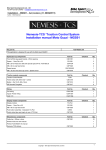
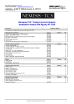
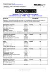
Bike Sport Developments Ltd – UK Tel 0044 (0)1327 263942 – [email protected] Installation – KTM RC8 (single coil) – AA (v04) Author – Mick Boasman Nemesis-TCS ‘Traction Control System Installation manual KTM RC8 (single coil) Type - AA For several years now a professional and well-developed traction control system for motorbikes has only been available to those with larger budgets or a top-level superbike team behind them. All of this has now changed !! 1 Copyright – Bike Sport Developments Ltd 2012 Bike Sport Developments Ltd – UK Tel 0044 (0)1327 263942 – [email protected] Installation – KTM RC8 (single coil) – AA (v04) Author – Mick Boasman Kit part No. Application - KTM RC08 single plug version TCS-KTM-RC08.AA R speed pick up components Rear speed bracket M8 x 20 low head zinc disk bolts (Ducati spec) Pt No. 7070 083 20 Speed sensor M6 x 16 , SS Allen dome head screw - Speed sensor Part No CSD1322 CSP1034 23813030401 CSP1019 Checked Qty 1 5 1 2 Traction module components Traction Control Module Carbon panel M5 x 40 zinc cap screw M5 plain washer, zinc M5 Nyloc, zinc Bobbin - Dia 10x15, M5 x12mm Spacers - 8mm x M5 for carbon panel M5 Serrated FlangeNut Part No TCM CSD1310 CSP1031 CSP1032 CSP1033 CSP1012 CSD1323 CSP1017 Checked Qty 1 1 4 18 4 3 4 6 Wiring Coil wiring CAN – PC wiring Inputs and power wiring Speed Opto coupler Throttle signal - quick link (red) Part No CSW1323 CSW1346 CSW1324 CSP1043 CSP1015 Checked Qty 1 1 1 1 1 Display module components TC-Pod Display module TC-Pod Spacer, round stepped tube TC-Pod mount bracket M3 x 8 button head - black M6 x 40 S/S cap head screw - black M6 x 75 zinc cap screw Push button assembly - blue/green TC-Pod Handlebar spacer 11mmOD x 9mm long - 6.5 ID Part No TC-Pod CSD1321 CSD1320 CSP1018 CSP1025 CSP1035 CS972 CSD1326 Checked Qty 1 1 1 2 1 1 1 1 Part No Checked Qty 1 TBA 6 Miscelaneous components Printed TCS over view manual manual Nemesis-TCS stickers CSP1022 IMPORTANT – To be read by ALL installers and owners Terms of use The presence of the Nemesis-TCS does not take away the responsibility of the rider to operate the bike correctly within their own abilities, the track conditions and the laws of physics. The system is designed to achieve greater on-track performance by the use of power modulation during wheel slip events, but in no way should it be considered possible for the system to recover from every conceivable loss of grip. The onus for safety always rests with the rider to stay within his or her own abilities, and to ensure that the ‘on-bike’ equipment is programmed, setup correctly, and an appropriate TC level selected for the skill of the rider, the bike and the track conditions. This equipment is intended for racing or track day performance use only and where exhaust emission controls are not applicable. By installing and using the Nemesis-TCS you automatically indemnify Competition Systems Ltd, suppliers and our authorised dealers from all first party or third party loss or damages. Normal components warranty is not affected 2 Copyright – Bike Sport Developments Ltd 2012 Bike Sport Developments Ltd – UK Tel 0044 (0)1327 263942 – [email protected] Installation – KTM RC8 (single coil) – AA (v04) Author – Mick Boasman TC Module Mounting: The TCS module mounts on the underside of the plastic tray pictured in image-1. This tray must be modified by drilling out the 4 corner positions to be clearance on the M5 screws supplied with this kit. The TCS module attaches to the carbon plate using the 3 rubber bobbins we supply in the kit. But it is important to fit some of the M5 washers under these bobbins in order to angle the TCS module forward by 7degrees. Refer to Image-2 o Under position 1 add 4 plain washers o Under position 2 add 3 plain washers o Under position 3 add 2 plain washers Note that these washers can be fitted either side of the bobbin to increase the length. When finally installed this should result in the module being horizontal with the ground with the bike resting on the wheels. Image 2 is shown without the plastic tray for clarity. Re-fit the plastic panel and suspend the new carbon panel beneath it using the 4 thin spacers, M5x40 cap screws and nyloc nuts. The Image-2 on the right shows the orientation of the carbon plate with the plastic plate removed for clarity. When finished the upper carbon face of the TC module should be uppermost and level with the floor when the bike is resting on its wheels. TCS Module orientation should be as seen in the diagram If necessary to ensure that the module is level after installation, use the spare washers we supply in the kit. Top View carbon face Front of bike TC-Pod (Display) Fitting: The Display pod is fitted to the left side of the headlight assembly as seen in Image-3 The mounting assembly uses these parts. o M6 x 75 cap bolt x 1 o M3 x 8mm Button head screw x 2 Important note – The TC-Pod supplied, as part of the TCS kit is not the same as the standard TC-Pod as used on many Ducati bikes. Do not attempt to swap parts The push button assembly is mounted on the left side handlebar clutch clamp as seen in image-4 using the spacer and longer screw. 3 Copyright – Bike Sport Developments Ltd 2012 Bike Sport Developments Ltd – UK Tel 0044 (0)1327 263942 – [email protected] Installation – KTM RC8 (single coil) – AA (v04) Author – Mick Boasman Rear Wheel Speed: Your TCS kit comes with a set of 5 new CAP bolts to replace the hexagonal ones used to mount the rear disc. These should be tightened and fitted using the same specifications of the standard bolts. Fit the new speed sensor to the bracket using one of the M6x16 dome head cap screws, fit using a non-permanent thread lock agent o Note that you may find it easier to remove the rubber O ring from the sensor and push it into the bracket first. Fit the sensor-mounting bracket to the rear disk hanger. The bracket will locate in the 10mm dia hole and is secured using the remaining M6x16 dome head screw. Fit using a non-permanent thread lock agent The sensor gap is fixed and no adjustment is required by the user. The design gap is between 1mm and 2.5mm New low profile cap bolt WIRING – IMPORTANT – Do not connect any of the three TCS connectors directly to any standard bike loom connectors (even if they fit). These 3 connectors must only be linked to the blue-banded connectors of the wiring we supply. Damage to the equipment or bike components may occur if this rule is ignored. Coil Wiring Locate the wiring loom with yellow identification - CSW1323. Connect the 6 way connector with the blue banding to connector 1 of the TCS Module. Route the wiring along the right side of the bike following the original wiring route. Disconnect the wiring from the Front coil and use the CSW1323 wiring loom to bridge the gap as shown below. Disconnect the loom wiring from the rear coil and use the CSW1323 wiring loom to bridge the gap as shown below. H orizo ntal c oi l w iri ng fro m b ike 2 1 1 C oi l H 3 2 1 4 5 6 V erti c a l c o il wi rin g from bi ke 2 1 2 1 C oi l V Vertical cylinder Horizontal cylinder 2 1 Connect the 6mm earth connection either to the rear cylinder head or the battery negative. Failure to fit a secure earth link will damage the TCS module and cause the engine to stop. Should it ever be necessary to isolate all TCS functions and return the bike to normal operation, simply remove these links and re-connect the coils back to their original loom connections. 4 Copyright – Bike Sport Developments Ltd 2012 Bike Sport Developments Ltd – UK Tel 0044 (0)1327 263942 – [email protected] Installation – KTM RC8 (single coil) – AA (v04) Author – Mick Boasman WIRING – IMPORTANT – Do not connect any of the three TCS connectors directly to any standard bike loom connectors (even if they fit). These 3 connectors must only be linked to the blue-banded connectors of the wiring we supply. Damage to the equipment or bike components may occur if this rule is ignored. Inputs and Power wiring Ensure all cables are not trapped when suspension or steering is moved and that the wire routes chosen do not restrict any control movement of the bike. Front speed – Connectors D and E The front speed sensor 3 way triangular connector can be found under the instrument housing. This 3 way connector provides the power and ground to the TCS as well as the front speed signal. Disconnect the front speed sensor and bridge the gap using the male and female 3 way connectors of the new wiring CSW1324 Use the cable ties we provide to give strain relief to these connections Rear speed – Connector A Route the rear speed sensor along the right side of the swinging arm using the brake hydraulic line as a guide. Use the cable ties provided and ensure this cable cannot be damaged or trapped during suspension movement B 2 1 3 A 1 E 3 2 CSD1341 D 1 2 1 4 5 5 8 2 CSD1341 – This small plug-in module must be fitted at all times. It acts as a signal dividor allowing a single front speed sensor to drive both the TCS and the standard dashboard. Without this module neither the TCS nor the standard dash will read the front speed. 3 2 1 C 1 TCS module – Connector 2 Locate the 8 way connector-2 with the blue band on the wiring loom and connect to the 8 way connector on the TCS module 3 Quick shift – Connector C Any type of quick shifter with either an ‘active high’ or ‘active low’ output can be used. 1 2 3 Battery + ground signal red black white Throttle The throttle input is the single wire B of this loom. This needs to be attached to the white signal wire multi-block connector image-6 located on the right side of the air box using the red quick link provided in the kit, as shown in the steps on the next page: 5 Copyright – Bike Sport Developments Ltd 2012 Bike Sport Developments Ltd – UK Tel 0044 (0)1327 263942 – [email protected] Installation – KTM RC8 (single coil) – AA (v04) Author – Mick Boasman The quick link is made up of three parts as seen here on the right: Using the green section with the slot, push it over the orange throttle signal wire of the bike loom until the wire rests at the bottom of the slot: The large red centre section must be fitted the correct way around or the link will not work. Locate the end with the sharp pointed tip protruding from the end of the outer body and screw this end onto the green section until it rests firmly against the wire. The sharp tip will pierce the outer sleeve but not sever the inner core of the wire: Strip back the sleeve of the throttle input wire on the TCS loom so that 8mm of inner metal core is exposed. Push this into the red cap as seen here on the right with inner core showing: Screw this cap and wire into the main body ensuring that metal inner core and wire cores are sandwiched and held securely. Shrink sleeving can be put over this quick link if required. TCS module – Connector 3 Locate the 4 way connector-3 with the blue band on the wiring loom and connect to the 4 way connector on the TCS module 3 B C A PC communication – Connector A All PC communication is achieved via the 4 way connector, this connector is live and should be protected from water ingress when not being used. Display TC-Pod – Connector B Connect this 8 way directly to the TC-Pod display unit Pit limiter switch input – Connector C The pit limiter switch CSP1041 links at point K and may be mounted to any convenient place accessible by the rider. We do not however make a specific handlebar mounting kit for the RC8 This item is an optional extra and not supplied as part of the kit. PC Setup Your TCS module should be loaded with the following maps: 118_RC8_1_Sxx_Rxx.S19 Sxx – Slip map version Rxx – revision version Position value – 0.42 to 0.48 – Refer to WinTC View Data Note : The WinTC installation guide can be found in the Nemesis-TCS manual. 6 Copyright – Bike Sport Developments Ltd 2012