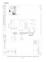
1
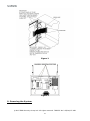
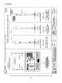
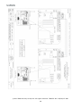
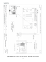
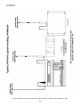
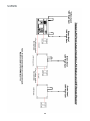
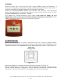
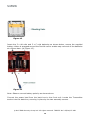
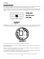
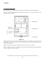
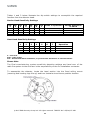
INSTALLATION MANUAL Table of Contents Section Page No 1. INTRODUCTION ................................................................................................ 3 2. WARNINGS AND CAUTIONS ............................................................................... 3 3. UNPACKING ..................................................................................................... 3 4. INSTALLATION ................................................................................................. 4 5. CONTROL PANEL - REMOVING ITEMS BEFORE MOUNTING ..................................... 4 6. MOUNTING THE ENCLOSURE TO A WALL ............................................................. 4 7. REPLACING ITEMS AFTER MOUNTING .................................................................. 4 8. MOUNTING DIAGRAMS ...................................................................................... 5 9. POWERING THE SYSTEM .................................................................................... 6 10. EXTERNAL WIRING .......................................................................................... 7 10.1 HARDWIRED SOUNDER..................................................................................... 8 10.2 HARDWIRED CALL POINT .................................................................................. 8 10.3 DEVICE WIRING ............................................................................................ 8 11. INSTALLATION ADVICE. ................................................................................... 8 12 DEVICE INSTALLATION .................................................................................... 26 12.1 RADIO CALL POINT ........................................................................................ 26 12.2 RADIO SOUNDER........................................................................................... 27 12.3 RADIO DETECTORS ........................................................................................ 30 12.4 INPUT/OUTPUT UNITS .................................................................................... 32 12.5 COMBINED SOUNDER SENSORS ......................................................................... 33 13. CONTROLLER INFORMATION ........................................................................... 36 ©2015 EMS Security Group Ltd. All rights reserved. TSD252 Iss 2 25/06/15 AJM 2 1. Introduction This manual provides an installation guide to the EMS TemPoint, Fire Control Panel and peripheral devices. It is important that for correct installation, the instructions given in this manual are followed. Whilst this manual provides an overall installation guide, refer to the User Manual for details on how to operate the system. 2. Warnings and Cautions It is very important that the procedures in this installation manual are carefully followed. This will prevent injury. The user of this manual should be a suitably trained installer and should be familiar with all of the relevant regulations. When installing EMS TemPoint Control Panel and peripherals, it is important to use the correct fixings, which are suitable for the type of surface being secured to. TemPoint includes components, susceptible to damage from Electro Static Discharge (ESD). These components can be permanently damaged through routine handling, if precautions are not observed. Where handling is unavoidable, adequate earthing precautions should be taken. E.g. an earthed wrist strap. Minimise the handling of static sensitive PCB devices. Also always transport “loose” PCB’s in containers, manufactured with ESD protective properties. Also avoid placing static sensitive devices on plastic surfaces. 3. Unpacking TemPoint control panels are simple to install, provided that the recommended procedures in this manual are followed. Refer to the Engineers Operating Guide for details on the programming of system operation, and the User Manual for the overall system operation. Care should be taken when handling TemPoint. Dropping any of the parts onto hard surfaces may cause damage to the case and internal circuitry. Products should be kept in their packaging until installation. This minimises any risk of damage. Retain all packaging until the installation activities have been completed. Any products surplus to requirements, or requiring returning to EMS, should be returned in the original packaging. CONTROL PANELS ARE SUPPLIED WITH ALL DETECTOR ZONES IN TEST. PLEASE REFER TO THE ENGINEERS OPERATING GUIDE TO MAKE ACTIVE. ©2015 EMS Security Group Ltd. All rights reserved. TSD252 Iss 2 25/06/15 AJM 3 4. Installation Following the Site Survey, System Control Panels should be positioned as stated considering:The recommended minimum distance between metal objects or equipment for the aerial is 400mm. The recommended minimum distance to any electrical equipment is 2 metres, (See Figure 1). 5. Control Panel - Removing Items before Mounting Before mounting the unit, it is necessary that certain items be removed, so as to prevent the risk of damage to the internal circuitry. Remove the Door Assembly from the Back Box. To achieve this, disconnect the Ribbon Cables and Earth links, loosen the hinge screws on the Back Box side of the hinge and pull the door away. Ensure that the Door Assembly is suitably stored and that ESD precautions are observed (see Figure 2). Establish the required cable entries. Knockouts should be made prior to fixing the Back Box to the wall. Ensure that the Back Box is free of swarf and other debris. 6. Mounting the Enclosure to a Wall It is recommended that the Control Panel be mounted in accordance with the site survey so that the display is at eye level. Achieve this firstly by securing it to the wall, via the single fixing “keyhole”, located in the top centre of the box. The box should be hung and levelled, allowing holes to be marked out for each of the four remaining mounting holes (shown on figure 3). Once the Back Box is fitted to the wall, all external cabling should be run to the box, including the provision of an unswitched 240 volt supply. The mains cable should be dressed away from the main radio PCB and should be as short as possible. 7. Replacing Items after Mounting Replace the Door assembly by reversing the steps given in Section 5, ensuring that all electrical connections, including the earth leads, are made. Ensure that both UHF and VHF aerials are fitted to the top of the Control Panel. To ensure correct fitment, the aerial identified with the coloured band must be fitted to the connector identified with the coloured band. If high gain aerials are to be used they must be positioned in accordance with the site survey. ©2015 EMS Security Group Ltd. All rights reserved. TSD252 Iss 2 25/06/15 AJM 4 8. Mounting Diagrams Figure 1 ©2015 EMS Security Group Ltd. All rights reserved. TSD252 Iss 2 25/06/15 AJM 5 Figure 2 Figure 3 9. Powering the System ©2015 EMS Security Group Ltd. All rights reserved. TSD252 Iss 2 25/06/15 AJM 6 The TemPoint Control Panel has an internal 3 amp power supply and charger as standard. On larger systems and where hard-wired sounder circuits are used, it may be necessary to provide an additional power supply or increase the size of the system power supply and charger. When using an additional power supply, it should be mounted in an appropriate cabinet adjacent to the control panel. Should this be impractical, the maximum distance between the Control Panel and power supply/charger should not exceed 3 metres. Ensure that the voltage drop between the supply and the main panel does not exceed 0.5v. The 240V power supply to the Control Panel must be made by way of an individual fused spur, situated adjacent to the Control Panel. The fused spur must have it’s own power supply circuit fitted with a 3 Amp fuse. Affix a red circuit breaker, labelled “Fire Alarm, Do Not Switch Off”, to the circuit. It is recommended that the circuit breaker be secured from unauthorised access. The fused spur should be similarly labelled as “Fire Alarm”. When powering up, the following procedure must be followed. If the panel is switched off, apply the mains power to the unit and connect the batteries (observing the correct polarity). After the system has completed its initialisation sequence, the display will show, Figure 4 followed by Figure 5 Warm Start FIRIS OS Searching . . . . . . . . . . V1.6 01 02 03 04 05 06 Figure 4 Figure 5 When the Control Panel is first powered up, the “General Fault” LED will illuminate and the fault buzzer will sound. This continues whilst the system initialises itself and runs through self-test routines. Once initialised, the green “Power” LED will illuminate. At this time the “General Fault” LED will also be illuminated, whilst the display will indicate a “PR” fault. Press “SILENCE ALARM” followed by “RESET” to clear this LED. The Control Panel will run through a series of diagnostic self tests. The illumination of the applicable LED and the sounding of the fault buzzer will indicate any errors on the display. Under normal non fault conditions, the display will indicate status as “Normal” (see Figure 6). If the Key Switch is left in the “On” position, the display will indicate that the panel is in “Access mode” (see Figure 7). EMS FIRE SYSTEMS LTD Status Normal DATE EMS FIRE SYSTEMS LTD Panel in Access TIME 0 FOR ACCESS Figure 6 TIME Figure 7 10. External Wiring ©2015 EMS Security Group Ltd. All rights reserved. TSD252 Iss 2 25/06/15 AJM 7 10.1 Hardwired Sounder The TemPoint Control Panel includes provision for two hardwired sounder circuits. The circuitry monitors two pairs of conductors fitted with 4k7 End of Line resistors. No connection to the control Panel should be made at this stage. The maximum current permitted is 250mA per circuit. 10.2 Hardwired Call Point The TemPoint Control Panel includes provision for a hardwired Call Point interface. The Control Panel monitors this input via a 4k7 End of Line resistor. No connection to the Control Panel should be made at this stage. Note: The external connections & wiring must be tested in the conventional manner. Under no circumstances should the system circuitry be tested using a meggar tester, once the connections to the control panel, or peripherals, has been made. 10.3 Device Wiring Using an Ohmmeter, check both sounder circuits to ensure that they have a 4.7k ohm resistance across the connections and that the resistance between each connection and the Control Panel earth point is greater than 20 M Ohm. Check any Call Point external wiring. The resistance across the Call Point connection should read 4.7k. Ensure that the resistance between each connection and the Control Panel earth point is greater than 20 M Ohm. Once external wiring circuits have been checked, make the connections to the control panel. The Control Panel should be powered down prior to termination. Connect all external wiring to the applicable Control Panel terminals (see drawing p02910). Upon completion of this, re-power the Control Panel. 11. Installation Advice. Ensure that you have all equipment required to complete the installation of TemPoint. Ensure that the correct fixings and fasteners are used for all installation work. Observe ESD precautions. Familiarise yourself with the system details and layout, before commencing any installation activity. Any anomalies must be addressed with the Surveyor, End user or the equipment supplier. Ensure that the Control Panel back box is clean and free of swarf prior to fitting the internal assemblies. Also ensure that aerials are fitted with anti tamper cones before applying 230V to the control panel. The 240V power supply to the Control Panel must be made by way of an individual fused spur, situated adjacent to the Control Panel. The fused spur must have it’s own power supply circuit fitted with a 3 Amp fuse. Affix a red circuit breaker, labelled “Fire Alarm, ©2015 EMS Security Group Ltd. All rights reserved. TSD252 Iss 2 25/06/15 AJM 8 Do Not Switch Off”, to the circuit. It is recommended that the circuit breaker be secured from unauthorised access. The fused spur should be similarly labelled as “Fire Alarm”. Wherever practical, fix detectors so that the red LED faces the main entrance to the room. Should it be necessary to remove the two aerials fitted to the Control Panel, ensure that when refitted, the coloured band on the aerial corresponds with the coloured disk on the BNC connector on the panel. Ensure that the 240V AC mains supply is fused and unswitched. ©2015 EMS Security Group Ltd. All rights reserved. TSD252 Iss 2 25/06/15 AJM 9 ©2015 EMS Security Group Ltd. All rights reserved. TSD252 Iss 2 25/06/15 AJM 10 ©2015 EMS Security Group Ltd. All rights reserved. TSD252 Iss 2 25/06/15 AJM 11 ©2015 EMS Security Group Ltd. All rights reserved. TSD252 Iss 2 25/06/15 AJM 12 ©2015 EMS Security Group Ltd. All rights reserved. TSD252 Iss 2 25/06/15 AJM 13 ©2015 EMS Security Group Ltd. All rights reserved. TSD252 Iss 2 25/06/15 AJM 14 ©2015 EMS Security Group Ltd. All rights reserved. TSD252 Iss 2 25/06/15 AJM 15 ©2015 EMS Security Group Ltd. All rights reserved. TSD252 Iss 2 25/06/15 AJM 16 ©2015 EMS Security Group Ltd. All rights reserved. TSD252 Iss 2 25/06/15 AJM 17 ©2015 EMS Security Group Ltd. All rights reserved. TSD252 Iss 2 25/06/15 AJM 18 ©2015 EMS Security Group Ltd. All rights reserved. TSD252 Iss 2 25/06/15 AJM 19 ©2015 EMS Security Group Ltd. All rights reserved. TSD252 Iss 2 25/06/15 AJM 20 ©2015 EMS Security Group Ltd. All rights reserved. TSD252 Iss 2 25/06/15 AJM 21 ©2015 EMS Security Group Ltd. All rights reserved. TSD252 Iss 2 25/06/15 AJM 22 ©2015 EMS Security Group Ltd. All rights reserved. TSD252 Iss 2 25/06/15 AJM 23 ©2015 EMS Security Group Ltd. All rights reserved. TSD252 Iss 2 25/06/15 AJM 24 ©2015 EMS Security Group Ltd. All rights reserved. TSD252 Iss 2 25/06/15 AJM 25 12 Device Installation 12.1 Radio Call Point Ensure that all Call Points are sited in accordance with the survey and design details. All Call Points must be surface mounted. Insert the Call Point key as shown in Figure 8. Remove the front cover. (See Figure 9). Figure 9 Figure 8 Remove the resettable element. (Also retain this for future use) This will expose the 2 internal assembly fixing screws (as shown in Figure 10). Fixing Screws Figure 10 Remove the fixing screws and separate the back box from Transmitter / Battery section. ©2015 EMS Security Group Ltd. All rights reserved. TSD252 Iss 2 25/06/15 AJM 26 Mount the back box 1.4m from the floor, using suitable fixings and fasteners. A minimum of 2 mounting holes must be used. Countersunk head screws must be used to avoid the possibility of causing damage to the internal components. Locate the Transmitter/Battery section into the back box, ensuring that the tamper switch operates correctly. The switch should also make contact with the rear of the back box/wall. (Established by the switch “clicking”). Now replace the internal assembly fixing screws. Care must be taken, as over tightening of the screws can prevent the element dropping on activation. Finally, reapply the element and fix the front cover back into place. 12.2 Radio Sounder Ensure that all sounders are sited in accordance with the survey and design details. Remove the two assembly screws from the front of the sounder. This will allow the main Transmitter section to be separated from the Battery/Back box section. (See Figure 11). Figure 11 Remove the batteries to expose the mounting holes as shown in Figure 12. Affix the back box to the wall using no.8 countersunk screws with suitable fixings. Ensure that the Sounder orientation is correct and that countersunk head screws are used so as to prevent the possibility of damaging the internal components. ©2015 EMS Security Group Ltd. All rights reserved. TSD252 Iss 2 25/06/15 AJM 27 Figure 12 Insert the 3 x AA cells and 3 x C cells batteries as shown below, ensure the supplied battery ribbon is wrapped around the first AA cell to enable easy removal of the batteries at a future date. (As Figure 13). Figure 13 Note: Observe correct battery polarity as shown above. Connect the power lead from the back box to the front unit. Locate the Transmitter section into the back box, securing in place by the two assembly screws. ©2015 EMS Security Group Ltd. All rights reserved. TSD252 Iss 2 25/06/15 AJM 28 ©2015 EMS Security Group Ltd. All rights reserved. TSD252 Iss 2 25/06/15 AJM 29 12.3 Radio Detectors Ensure that all Detectors are sited in accordance with the survey and design details and that, wherever practical, the red LED faces the main entrance to the room. If the Detectors are complete, remove the ceiling mounting plate by first disengaging the detector head by turning it counter clockwise. This exposes the Radio PCB (see Figure 14). Figure 14 Disengage the ceiling mount by pressing down the locking pin (see Figure 15) and turning the radio module counter clockwise whilst pushing it against the ceiling mount. Figure 15 The ceiling mount will now be available for fixing to the ceiling. Ensure that the Detector head is suitably stored so as to prevent the possibility of accidental damage. Fix the ceiling mounting plate to the ceiling using suitable fixings and fasteners. A minimum of two mounting holes must be used. It is important that fastener heads are flush or sub-flush with the internal surface of the ceiling mount, to avoid the risk of damaging the battery PCB. ©2015 EMS Security Group Ltd. All rights reserved. TSD252 Iss 2 25/06/15 AJM 30 The EMS Detector range are now supplied with a Dual Detector head, which is able to detect either smoke or heat by simply changing the head settings. Behind the Detector head module, a bank of 7 dip switches is located. The switch configurations provide much different functionality of the detector head and allow either smoke or heat mode to be selected. The benefits of the new Dual Detector head module is to allow easy interchanging between heat and smoke modes without having to purchase a new head module. The tables below illustrate the dip switch settings to accomplish the required function from the detector head. Smoke Head Sensitivity Settings Sw 1 Off Off On On Sw 2 Off On Off On Sw 3 Off Off Off Off Sw 4 On On On On Sw 5 Off Off Off Off Sw 6 X X X X Sw Mode of Operation 7 On High Sensitivity On Normal Sensitivity On Low Sensitivity On Low Sensitivity + AVF Table 1 Smoke Sensitivity % Per M 1.6 2.3 3.0 3.0 + AVF Heat Head Sensitivity Settings Sw 1 Off Off On On Sw 2 Off On Off On Sw 3 Off Off Off Off Sw 4 Off Off Off Off Sw 5 On On On On Sw 6 X X X X Sw Mode of Operation 7 On 58C ROR On 58C fixed On 75C fixed On 82C fixed Table 2 X – Not Used ROR – Rate of Rise AVF - Accelerated Alarm Verification, to prevent false alarms due to transient smoke. Dual Detector Sensitivity The Dual Detector set into single smoke or heat mode has new specified sensitivity levels of detection. These are supported by current standards (EN54 part 5 for smoke and EN54 part 7 for heat). The final commissioning, system sensitivity detection settings and hand over of the Radio Fire System to the end user is the responsibility of the fire installation contractor. To reassemble the detector, locate the Transmitter/Battery section into the fixed ceiling mount (ensuring that locating lugs line up) and turn clockwise to achieve a positive location. Locate the detector head to the fixed module, turning clockwise to achieve a positive location. ©2015 EMS Security Group Ltd. All rights reserved. TSD252 Iss 2 25/06/15 AJM 31 12.4 Input/Output Units Ensure that all I/O Units are sited in accordance with the survey and design details. Remove the two lid retaining screws situated on the front cover. The front section of the unit can now be removed. Figure 16 Offer the unit up to the wall and using the back plate as a template mark out the three fixing holes. The unit can be fixed to the wall and all external wiring connections made (see drawing P04242). When all connections have been made to the unit the lid can be re-fixed. NOTE: A metal box version is available, which has the same input and output capability with the addition of external aerials. ©2015 EMS Security Group Ltd. All rights reserved. TSD252 Iss 2 25/06/15 AJM 32 12.5 Combined Sounder Sensors Ensure that all sounder sensors are sited in accordance with the survey and design details and that, wherever practical, the red LED faces the main entrance to the room. The sounder sensor is shown in Figure 17 and consists of two separate sections. The mounting plate is shown in Figure 18 and can be removed by turning the mounting plate whilst holding the sounder/sensor section. Figure 17 Figure 18 The mounting plate will now be available for fixing to the ceiling. Ensure that the main section is suitably stored so as to prevent the possibility of accidental damage. Fix the ceiling mounting plate to the ceiling using suitable fixings and fasteners. A minimum of two mounting holes must be used. It is important that fastener heads are flush or sub-flush with the internal surface of the ceiling mount, to avoid the risk of damaging the head unit. Setting sensitivity The EMS Sounder Sensor is now supplied with a Dual Detector element, which is able to detect either smoke or heat by simply changing the head switch configuration. The benefit of the new Dual Detector element is to allow easy interchanging between heat and smoke modes without having to purchase a new device. The sensitivity switch location is shown below. Sensitivity Switches (Exposed upon ‘AA’ battery removal) ©2015 EMS Security Group Ltd. All rights reserved. TSD252 Iss 2 25/06/15 AJM 33 Tables 1 and 2 below illustrate the dip switch settings to accomplish the required function from the detector head. Smoke Head Sensitivity Settings Sw 1 Sw 2 Sw 3 Sw 4 Sw 5 Sw 6 Off Off On On Off On Off On Off Off Off Off On On On On Off Off Off Off X X X X Sw 7 Mode of Operation Smoke Sensitivity % Per M On High Sensitivity On Normal Sensitivity On Low Sensitivity On Low Sensitivity + AVF Table 1 1.6 2.3 3.0 3.0 + AVF Heat Head Sensitivity Settings Sw 1 Sw 2 Sw 3 Sw 4 Sw 5 Sw 6 Off Off On On Off On Off On Off Off Off Off Off Off Off Off On X On X On X On X Table 2 Sw 7 Mode of Operation On On On On 58C ROR 58C fixed 75C fixed 82C fixed X – Not Used ROR – Rate of Rise AVF - Accelerated Alarm Verification, to prevent false alarms due to transient smoke. Please Note The Final commissioning, system sensitivity detection settings and hand over of the radio fire system to the end user is the responsibility of the fire installation contractor. To reassemble the detector, locate the head section into the fixed ceiling mount (ensuring that locating lugs line up) and turn clockwise to achieve a positive location. Figure 19 ©2015 EMS Security Group Ltd. All rights reserved. TSD252 Iss 2 25/06/15 AJM 34 Within the Volume/Option switches, switch number 1, when in the “ON” position sets the tamper to disabled. However flicking the switch to the “OFF” position enables the tamper feature. This would be set before the device is set into it’s final location. ©2015 EMS Security Group Ltd. All rights reserved. TSD252 Iss 2 25/06/15 AJM 35 13. Controller Information TECHNICAL INFORMATION FOR THE TEMPOINT CONTROLLER Dimensions: Operating Frequencies: Operating Temperature: Humidity: Channel Spacing: Output Transmitter Power: Supply: Current Consumption: Operating Voltages: Battery space: Inputs: Outputs: Recommended battery replacement intervals: 330mm x 450mm x 116mm VHF – 173.2 MHz – 173.5MHz (receiver) UHF – 458.5 MHz – 459.5 MHz (transmitter) -10 to 55 degrees C Up to 75% non-Condensing. 25 kHz 0.75W (500 mW) (+ 27DBH) 240v 50 Hz 260mA in standby 24v DC nominal 2 x 12volt 9Ah batteries (not supplied) EMS only recommend: Panasonic Model No: UP-RW1245P1 or a battery of equivalent specification 1 x 27v DC 2 x 0.25amp 24v DC sounder outputs 2 x auxiliary fire relays 2 x auxiliary fault relays 1 x RS 485 serial port 1 x RS 232 serial port Standby 9Ah batteries – 2 years Lithium clock and RAM batteries – 5 years (Re-order no – 5-5812) ©2015 EMS Security Group Ltd. All rights reserved. TSD252 Iss 2 25/06/15 AJM 36