1
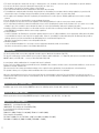
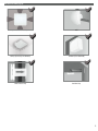
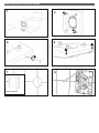
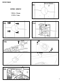
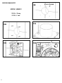
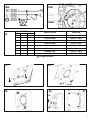
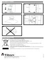
G G Installation manual Solitude - dMEV unit Introduction Solitude (fig. 1) is a decentralised mechanical ventilation unit designed to ensure air extraction in small/medium-sized rooms. Suitable for air discharge directly to the outside or in the presence of short ducted system. Wall, ceiling or window installation (fig.2). Fig. 1 Read this manual carefully before using the product and keep it in a safe place for reference. This product was constructed up to standard and in compliance with regulations relating to electrical equipment and must be installed by technically qualified personnel. The manufacturer assumes no responsibility for damage to persons or property resulting from failure to observe the regulations contained in this booklet. TECHNICAL SPECIFICATIONS • Material: High quality, impact and UV-resistant ABS colour RAL 9010. • Design front cover removable for cleaning without the use of tools. • Rear reinforcement ring to prevent spigot deformation during installation. • High efficiency aerodynamic fan with “winglet” blades to optimise quietness and efficiency. • Single phase EC Brushless motor with integral thermal protection. • Motor mounted on high quality ball bearings. • The fan is double insulated: no earth connection is required. • Trickle speed selectable during installation (see fig.16) • Option to boost from trickle through LS connection. • Installation type selection available (through wall or ducted). • Integral over-run timer. • IPX4 degree of protection. • Power supply 220V to 240V~ 50Hz. Model Solitude Airflow m3/h l/s 83/47/36/29/21 23/13/10/8/6 Static pressure Pa max Power W max Sound pressure dB(A) @3m 27 2.5 26/23/13/19/11 PRECAUTIONS FOR INSTALLATION, USE AND MAINTENANCE 1 • The device should not be used for applications other than those specified in this manual. • After removing the product from its packaging, verify its condition. In case of doubt, contact a qualified technician. Do not leave packaging within the reach of small children or people with disabilities. • Do not touch the appliance with wet or damp hands/feet. • The device is not intended for use by persons (including children) with reduced physical, sensory or mental capacities or those with a lack of experience and knowledge, unless they have been given supervision or instruction concerning use of the device from a person responsible for their safety. Children should be supervised to ensure that they do not play with the device. • Do not use the product in the presence of inflammable vapours, such as alcohol, insecticides, gasoline, etc. • If any abnormalities in operation are detected, disconnect the device from the mains supply and contact a qualified technician immediately. Use original spare parts only for repairs. • The electrical system to which the device is connected must comply with regulations. • Before connecting the product to the power supply or the power outlet, ensure that: - the data plate (voltage and frequency) correspond to those of the electrical mains - the electrical power supply/socket is adequate for maximum device power. If not, contact a qualified technician. • The device should not be used as an activator for water heaters, stoves, etc., nor should it discharge into hot air/fume vent ducts deriving from any type of combustion unit. It must expel air outside via its own special duct. • Operating temperature: 0°C up to +50 °C. • The device is designed to extract clean air only, i.e. without grease, soot, chemical or corrosive agents, or flammable or explosive mixtures. • Do not leave the device exposed to atmospheric agents (rain, sun, snow, etc.). • Do not immerse the device or its parts in water or other liquids. • Turn off the main switch whenever a malfunction is detected or when cleaning. • For installation an omnipolar switch should be incorporated in the fixed wiring, in accordance with the wiring regulations, to provide a full disconnection under overvoltage category III conditions (contact opening distance equal to or greater than 3mm). • If the supply cord is damaged, it must be replaced by the manufacturer, its service agent or similarly qualified persons in order to avoid a hazard. • Do not obstruct the fan or exhaust grille to ensure optimum air passage. • Ensure adequate air return into the room in compliance with existing regulations in order to ensure proper device operation. • If the environment in which the product is installed also houses a fuel-operating device (water heater, methane stove etc., that is not a “sealed chamber” type), it is essential to ensure adequate air intake, to ensure good combustion and proper equipment operation. • Install the product so that the impeller is not accessible from the air outlet side as verified by contact with the Test Finger (Test probe “B” of the norm EN61032) in compliance with the current safety regulations. • Ceiling installation In order to guarantee the IPX4 degree of protection against moisture in case of ceiling installation, use the appropriate ceiling mount kit, which is not included. Use only the rear entry hole for supply cables. If there is a possibility of condensation along the air discharge duct, provide a drainage system to prevent condensation from discharging into the environment through the fan. Attention: do not mount the product on the ceiling without this kit. • Window installation In case of window installation it is necessary to use the appropriate window kit, which is not included. Attention: do not mount the product on the window without this kit. OPERATION The fan is provided with over-run timer, adjustable from 0 to approx. 30 minutes via trimmer (fig. 15B). The fan runs continuously at selected trickle speed (set by the jumper switch combination - see figure 16) and can be boosted with a dedicated ON/OFF switch (or HY, PIR, CO2… sensor) or with a light switch (fig. 14B). In some jumper switch combinations the “constant flow” mode is activated. In these cases, the airflow detection system will detect the installation duct resistance and also react to external wind conditions to ensure the fan maintains a constant extraction rate. This can cause the fan to ramp up and down and may not be required in some applications (it can actually cause noise discomfort). The product is factory set on a jumper switch combination where the constant flow mode is not activated. When the external switch is turned on, the fan is boosted. After the external switch is turned off, the fan continues to run at boost speed for a settable period of time, then it returns to selected trickle speed. The over-run timer function is activated only if the external switch has been on for at least 60 seconds. INSTALLATION TYPE SETTING Installation type can be selected using JUMPERS between the following options: through wall or ducted. See figure 16. TRICKLE SPEED SETTING Trickle speed can be selected using JUMPERS among the following options: 6-8-10-13 l/s. See figure 16. STANDARD CONFORMITY 2006/95/EC Low Voltage Directive (LVD) 2004/108/EC Electromagnetic Compatibility (EMC), in conformity with the following standards: Electrical Safety EN60335-1(2008); EN 60335-2-80(2005); EN 60335-2-80/A2(2009) Electromagnetic Compatibility EN 55014-1(2006)+A1+A2; EN 55014-2(1997)+A1(2001)+A2(2008)+IS1(2007) EN 61000-3-2(2006)+A1(2009)+A2(2009); EN 61000-3-3(2008). 2 INSTALLATION (Fig.2) perimetrical exhausting wall ceiling (accessory on demand) window (kit on demand) direct exhausting short ducting 3 MOUNTING AND ELECTRICAL WIRING 4 5 66 7 8 Ø 1 Solitude= ø99 mm SURFACE CABLE 4 x ø 5 mm 9A H03VV-F ; H05VV-F 3 X 0.5 ÷ 1.5 mm2 4 X 0.5 ÷ 1 mm2 d Ø d 12A 11A Ø 10A ø 10mm 13A 5 RECESSED CABLE ENTRY 9B H03VV-F ; H05VV-F 3 X 0.5 ÷ 1.5 mm2 4 X 0.5 ÷ 1 mm2 6 10B 11B 12B 13B 4 x ø 5 mm 15B + 14B TIMER - Solitude 16 1 JUMPER 2 3 INSTALLATION AIRFLOW constant flow 47m3/h - 13l/s constant flow 36m3/h - 10l/s constant flow 29m3/h - 8l/s constant flow 21m3/h - 6l/s in room 47m3/h - 13l/s in room 29m3/h - 8l/s through wall 47m3/h - 13l/s through wall 29m3/h - 8l/s = Jumper present 17 18 CLICK 19 20 21 ON OFF 7 MAINTENANCE / CLEANING 22 23 24 25 26 DISPOSAL AND RECYCLING International House, Peartree Road, Stanway, Colchester, Essex CO3 0JL Tel: +44 (0)1206 814879 Fax: +44(0)1206 543126 Email: [email protected] Web: www.titon.com CFI00020 - 0614 Information on disposal of units at the end of life. This product complies with EU Directive 2002/96/EC. The symbol of the crossed-out dustbin indicates that this product must be collected separately from other waste at the end of its life. The user must, therefore, dispose of the product in question at suitable electronic and electro-technical waste disposal collection centres, or else send the product back to the retailer when purchasing a new, equivalent type device. Separate collection of decommissioned equipment for recycling, treatment and environmentally compatible disposal helps to prevent negative effects on the environment and on health and promotes the recycling of the materials that make up the equipment. Improper disposal of the product by the user may result in administrative sanctions as provided by law.