1
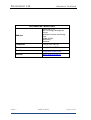
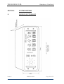
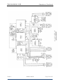
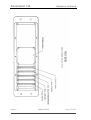
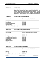
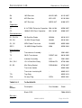
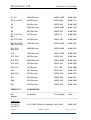
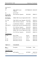
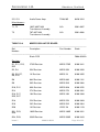
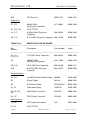
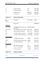
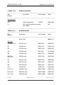
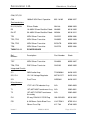
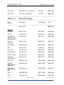
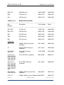
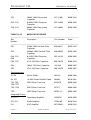
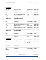
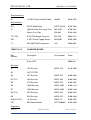
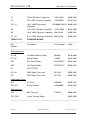
Sonavision Ltd.
Aberdeen, Scotland
OPERATION AND
INSTALLATION MANUAL
DETAILS OF THE EQUIPMENT
PART NUMBER:
3301
DESCRIPTION:
SUBCOM 2000 DIVING BELL EMERGENCY
COMMUNICATION SYSTEM MANUAL
Issue 1
3400-31-0016
Page 1 of 53
Sonavision Ltd.
Aberdeen, Scotland
APPROVALS
ORIGINATOR:
ENGINEER:
PRODUCTION:
ISS
DATE
0
29/03/10
1
R HARDIE
R.J HARDIE
DESCRIPTION
BY
DRAFT FOR APPROVAL
RH
CHK
RELEASE FOR PRODUCTION
2
3
4
5
The latest issue of this document is held in electronic form.
This is available from our website www.sonavision.co.uk
COPYRIGHT © SONAVISION LIMITED
AUGUST 2008
The copyright in this document is the property of Sonavision Limited. The document
is supplied by Sonavision Limited on the express terms that it may not be copied,
used, or disclosed to others except as authorised in writing by Sonavision Limited.
Sonavision Limited reserves the right to change, modify and update designs and
specifications as part of their ongoing product development programme.
Issue 1
3400-31-0016
Page 2 of 53
Sonavision Ltd.
Aberdeen, Scotland
TECHNICAL SUPPORT
Address
Sonavision LTD,
Unit 12 Energy Development
Centre,
Aberdeen Science and Energy
Park,
Bridge Of Don,
AB23 8GD,
Scotland
Telephone
+44 (0)1224 707737
Fax
+44 (0)1224 827290
Email
[email protected]
Website
www.sonavision.co.uk
Issue 1
3400-31-0016
Page 3 of 53
Sonavision Ltd.
Aberdeen, Scotland
MAINTENANCE AND WARRANTY POLICY
Sonavision Limited warrants that its products are free from defects at the
time of delivery and subject to the conditions listed below, undertakes to
repair, or at its option replace, any product found to be defective in material
or workmanship within one year after delivery, whichever is less, to the
original purchaser by Sonavision Limited or its authorised representative.
CONDITIONS
1. Sonavision Limited must be immediately notified of any suspected defect
and if advised by Sonavision Limited, the equipment subject to defect
shall be returned to Sonavision Limited, freight prepaid.
2. This warranty does not cover defects which are caused as a result of
improper usage, repair, maintenance, alteration or installation unless
such activities have been undertaken by Sonavision Limited or its
authorised representative.
3. On completion of any warranty work, Sonavision Limited will return the
equipment, freight prepaid.
4. Sonavision Limited retains the sole right to accept or reject any warranty
claim.
SAFETY AND ENVIRONMENTAL STATEMENT
1. Lethal voltages are exposed within the control unit when the top cover is
removed. The unit should always be disconnected from the mains
supply before removing or operating any internal components.
2. The unit should be earthed at all times.
3. The unit contains electrostatically sensitive devices (ESSD). Appropriate
static protection should be used when handling subassemblies.
RELATED DOCUMENTS
Document Number
Issue 1
Document Title
3400-31-0016
Page 4 of 53
Sonavision Ltd.
Aberdeen, Scotland
TABLE OF CONTENTS
SECTION 1
INTRODUCTION
1.1
1.2
1.2
INITIAL INSPECTION
PHYSICAL CHECK
ELECTRICAL CHECK
SECTION 2
SPECIFICATION
SECTION 3
SYSTEM COMPONENTS
3.1
3.2
3.3
3.4
3.5
SURFACE UNIT
BELL INTERNAL UNIT
BELL EXTERNAL UNIT
BELL BATTERY PACK
STROBE LIGHT ASSEMBLY
SECTION 4
SYSTEM DESCRIPTION
4.1
4.2
4.3
OVERVIEW
CONTROLS - BELL EQUIPMENT
CONTROLS - SURFACE UNIT
4.4
4.4.1
4.4.2
4.4.3
4.4.4
4.4.5
THEORY OF OPERATION
Receiver
Transmitter
Filter, Mixer and Oscillator
Voltage Regulator and Electronics Switch Circuits
Transducer
SECTION 5
INSTALLATION
5.1
5.2
5.3
SURFACE UNIT
BELL INTERNAL UNIT
BELL EXTERNAL UNIT
SECTION 6
COMMISSIONING
SECTION 7
SERVICE
7.1
7.2
7.3
OPERATIONAL SPARES
BASE SPARES - MAJOR ITEMS
BASE SPARES - COMPONENT PARTS
Issue 1
3400-31-0016
Page 5 of 53
Sonavision Ltd.
Aberdeen, Scotland
7.4
7.4.1
7.4.2
BATTERY MAINTENANCE
Surface Unit Batteries
Bell Unit Batteries
SECTION 8
OPTIONS
8.1
STROBE LIGHT
SECTION 9
SYSTEM DIAGRAMS
9.1
9.2
9.3
SURFACE UNIT DRAWINGS
BELL UNIT DRAWINGS
BATTERY CHARGER
SECTION 10
PARTS LISTS
Issue 1
3400-31-0016
Page 6 of 53
Sonavision Ltd.
SECTION 1
Aberdeen, Scotland
INTRODUCTION
The Subcom 2000 Emergency Bell Communication System is
designed primarily for emergency back-up to the umbilical wired
communications generally used in diving bell installations and
would be used in the event of failure of the wired system.
Subcom 2000 is a through water acoustic system and does not
rely on the integrity of the bell's umbilical, with its own battery
pack being sufficient for twenty hours of operation under normal
conditions. The surface receiver unit also has an internal
battery pack.
1.1
INITIAL INSPECTION
As soon as the system is unpacked, inspect for any damage that
may have occurred during transit. Retain all the packing
materials until the inspection is complete. If damage is found,
notify the carriers and authorised Sonavision Ltd Representative
immediately.
1.2
PHYSICAL CHECK
This check should confirm that there are no damaged
connectors, dents or scratches to the undersea units which
might result in excessive corrosion or water ingress.
1.3
ELECTRICAL CHECK
Connect the undersea units together as shown in the
interconnecting diagram and wire the penetrator cable into the
Bell Internal Unit.
Note the tow wire connection to Bell 24V a.c./d.c. supply is not
required for operation of voice communication.
The Bell Battery Pack is shipped fully charged and care should
be taken to avoid short circuits. Careful attention must be given
to the maintenance of the batteries as instructed in Section 7.4,
Battery Maintenance.
With the Transducer connected to the Bell External Unit a strong
signal should be heard from the loud-speaker on scratching the
Transducer surface.
A similar test with the Surface Unit should be conducted.
Final Functional test may be carried out by immersing both sets
of transducers in a bucket of water or by smearing the face of
each transducer with silicon grease and connect them face to
face bonded by the silicon grease. Then verify that two way
speech communications is possible.
Issue 1
3400-31-0016
Page 7 of 53
Sonavision Ltd.
SECTION 2
Aberdeen, Scotland
SPECIFICATION
Carrier:
25kHz ±0.01%
Transmission Frequency:
25.3 - 29.5kHz
Audio Freq. Bandwidth:
4.2kHz
Modulation:
Single Sideband
Suppressed Carrier
Transmit Power:
10 Watts
Receiver Sensitivity:
0.40 uBar
Audio Power:
1 Watt into 8 ohms
Power Requirements:
Surface Unit:
Bell Unit:
24V a.c./d.c. or 24V Bell
Battery Pack
Standby Current:
80mA
Transmit Current:
0.5 Amp
Transducers:
Polyurethane
Pre-stressed Piston
Beam Pattern:
Hemispherical
Depth Rating:
600 metres
Battery Capacity:
Surface Unit:
20 hours (20% transmit)
Encapsulated
Bell Unit:
Dimensions:
Surface Unit:
Issue 1
Internal Battery Pack
(rechargeable 115/240V
a.c. or 24 Volts d.c.)
20 hours (20% transmit)
Height:
Width:
Depth:
Weight:
160.0mm
520.0mm
310.0mm
16.5kg
Bell Internal Unit:
Height:
Width:
Depth:
Weight:
160.0mm
260.0mm
95.0mm
3.0kg
Bell Battery Pack:
Height:
Diameter:
465.0mm
152.0mm
3400-31-0016
Page 8 of 53
Sonavision Ltd.
Aberdeen, Scotland
Weight in Air:
11.0kg
Weight in Water: 3.5kg
Issue 1
Bell External Unit:
Height:
65.0mm
Diameter:
52.0mm
Weight in Air:
8.0kg
Weight in Water:
1.5kg
Bell Transducer:
Height:
125.0mm
Diameter:
60.0mm
Weight in Air:
1.5kg
Weight in Water:
0.5kg
3400-31-0016
Page 9 of 53
Sonavision Ltd.
Aberdeen, Scotland
SECTION 3
SYSTEM COMPONENTS
3.1
SURFACE UNIT:
Model 3301
a)
Hand Microphone:
Model 3301-1004
b)
Charge/Monitor Cable:
Model 3301-2001
c)
Tape/Unscrambler Cable Assembly: Model 3301-2002
d)
27kHz Transducer Assembly:
Model 3090
e)
Boom Headset:
Model 3260
(optional)
3.2
BELL INTERNAL UNIT:
Model 3303
3.3
BELL EXTERNAL UNIT:
Model 3302
a)
Transducer Assembly:
Model 3091
b)
R/A Penetrator Cable Assembly:
Model
3400-2001
(optional)
c)
Straight Penetrator Cable Assy:
Model
3400-2002
(optional)
3.4
3.5
BELL BATTERY PACK:
Model 3255
a)
Model 3255-2001
Power Cable Assembly:
STROBE LIGHT ASSEMBLY:
Model 3261
(optional)
a)
Model 3261-2001
Strobe Light Cable Assembly:
(A dummy connector will be supplied to cover the unused
battery terminals if a Strobe Light is not used).
Issue 1
3400-31-0016
Page 10 of 53
Sonavision Ltd.
Aberdeen, Scotland
SECTION 4
SYSTEM DESCRIPTION
4.1
OVERVIEW
The Subcom 2000 System is a wireless acoustic underwater
communication system designed for emergency backup
communications between a Diving Bell and its surface support.
The communications system operates as standard on 27kHz
SSBSC, compatible with present submersible equipment.
Transmit power is 10 Watts rms on communications.
All bell electronics and batteries are housed in an external
pressure housing, which results in greater safety and increased
reliability as helium ingress cannot occur and high internal
humidity problems do not exist. Only a minimum amount of
bell-space is occupied by the small Bell Internal Unit which
houses an 8 ohm loudspeaker which also serves as a
microphone.
The Surface Unit is provided with a variable squelch control for
use in noisy environments. This facility also helps to conserve
battery power.
Automatic gain control is provided on both Surface and Bell
Units, with manual variation of gain also being possible on the
Surface Unit.
The system also features the normal advantages of Single
Sideband Suppressed Carrier working (SSBSC) as opposed to
Double Sideband (DSB). For the same audio bandwidth the
noise bandwidth is halved giving a 3dB reduction in noise in an
SSBSC system. Additionally, all the transmitted power is audio
information in SSBSC system, whereas in a DSB system half
the power is wasted in transmitting an additional sideband
containing no extra information.
The Surface Unit contains an internal 24V rechargeable battery
pack and integral charger unit. The batteries may be charged
through the charge input socket. This should not be connected
during normal operation as it will reduce the transmitted power.
The Bell Unit has an external 24V battery pack which can be
recharged by the charger provided. This should be done by
disconnecting the cable between the Bell Battery Pack and the
Bell External Unit at the Electronics Housing and connecting this
to the charger.
At monthly intervals allow both surface and subsea battery
packs to fully discharge by leaving the systems switched on.
The subsea battery may be discharged more quickly be
connecting a 22 ohm wire-wound resistor (rated at 50 Watts and
mounted on a metal heatsink) to the battery for up to four hours
Issue 1
3400-31-0016
Page 11 of 53
Sonavision Ltd.
Aberdeen, Scotland
depending on the initial state of charge. Discharge ought to be
stopped when the voltage reaches 20 Volts. Take care not to
leave such a load connected after normal discharge, otherwise
the battery pack may be driven into DEEP DISCHARGE and be
PERMANENTLY DAMAGED.
4.2
Issue 1
CONTROLS - BELL INTERNAL UNIT
VOLUME:
This control is used to switch ON the Bell
Unit communications and the Strobe Light
and to vary the volume of the received
communications. When switched on the
unit is normally on receive.
PTT:
This control when depressed, switches the
Bell Unit to transit mode, enabling speech to
be input to the Bell Internal Unit speaker
which is configured as a microphone.
STANDBY:
In the UP position, this
switch allows normal received operation of
the system to be controlled by the ON/OFF
VOLUME control.
In the STANDBY
position, it enables the Power Fail Detect
Circuit to operate. This facility monitors the
bell supply (24V d.c. or a.c.), so that if a
power fail occurs, the Bell Unit is
automatically
activated
giving
communications and strobe.
NOTE:
If the Bell supply is not connected the
STANDBY position should not be used.
PING AUX:
In the ON position, this
switch will enable the auxiliary emergency
systems optional Strobe Light to be
activated when either:
a)
The communications channel is opened up
by virtue of the power fail detection circuitry
operating.
b)
The ON/OFF VOLUME control is turned to
the ON position. In the OFF position the
Strobe is disabled.
AUX SPEAKER:
This is a jack socket which when utilised
will disconnect the speaker mounted in the
control box and allow another suitable
loudspeaker of 8 ohms impedance to be
connected.
3400-31-0016
Page 12 of 53
Sonavision Ltd.
Aberdeen, Scotland
BELL SUPPLY:
4.3
This is a
gland situated on the side of the Bell
Internal Unit which allows entry of the 24V
supply required by the power fail detect
circuitry.
This is purely a monitoring
function and is not required to power the
Bell System. The External Battery Pack is
supplied to power the system since the
effects of supply-borne interference is
minimised and battery capacity can be more
accurately estimated with only one power
supply.
CONTROLS - SURFACE UNIT
FUSE:
Holder for system main fuse 1.25 inch 5
amp.
VOLUME:
This acts as the overall system power
switch and speech volume control. When
switched on the unit is normally on receive.
GAIN:
Controls gain of high frequency front end
stage.
Under normal conditions the
switched AGC position should be employed.
SQUELCH:
Variable squelch control which can be
disabled. This should be adjusted to give
no loud background noise in receive mode
except during voice transmission from Bell
Unit.
PING Rx:
Not Used.
PTT:
With SPEAKER/HEADSET switch set for
SPEAKER this control switches the Surface
Unit to transmit mode enabling speech to be
input to the integral loudspeaker which is
configured as a microphone.
SPEAKER/HEADSET:
Controls
type of speaker/microphone configuration.
SPEAKER position should be selected
when using a fist microphone with integral
PTT switch and internal loud-speaker.
HEADSET position should be selected
when using headset with combined boom
microphone and cable PTT switch.
Issue 1
HEADSET/
MICROPHONE
Connector for microphone or headset.
TRANSDUCER:
Connector for 27kHz Surface Transducer.
3400-31-0016
Page 13 of 53
Sonavision Ltd.
4.4
Aberdeen, Scotland
TAPE/UNSC.:
Connector for direct output of transmitted
and received speech, suitable for tape
recording or connection to a helium speech
unscrambler.
CHARGE:
Connector for mains or 24V d.c. battery
charging supply input.
PING TDCR:
Not Used.
THEORY OF OPERATION
The basic circuitry of the Subcom 2000 System is identical for
both Surface and Bell Units and the following technical
description will apply to both units.
The Subcom 2000 is an SSBSC transceiver operating on the
upper sideband of a 25kHz crystal controlled carrier. The
system is composed of five basic units, as follows:
4.4.1
Receiver
Acoustic sound pressure waves are sensed by the Transducer
which converts them into electrical energy. These signals are
fed to the input of the receiver. The signals are amplified by the
high frequency (27kHz) front end section of the receiver. The
high frequency section of the receiver contains the automatic
gain control (AGC) element of the receiver which will be referred
to later. The amplified signal from the high frequency section of
the receiver is then connected to the bandpass filter where the
signal is band limited to remove noise and provide improved
selectivity of received signals.
The signal is then fed to the chopper mixer circuit where it is
mixed with a 25kHz signal from the crystal oscillator. This
process produces sum and difference frequencies between the
received signal and the crystal oscillator. The difference
frequency is then filtered out by the lowpass filter which follows
the mixer circuit. This audio signal is now coupled to the
Preamplifier which, after amplification, couples the signal to the
volume control where its level can be adjusted before going to
the audio power amplifier and AGC amplifier, which further
amplifies the audio signals and converts it to a d.c. level for the
purpose of controlling the gain of the receiver high frequency
front end.
4.4.2
Transmitter
Upon pressing the PTT switch, audio signals from the device
acting as the microphone (ie. a fist microphone loudspeaker or
boom microphone) will be coupled to the microphone amplifier
circuit. This signal is then mixed with a signal from the crystal
Issue 1
3400-31-0016
Page 14 of 53
Sonavision Ltd.
Aberdeen, Scotland
oscillator by the chopper mixer circuit. This produces both an
upper and lower sidebands. The bandpass filter then selects
the upper sideband signal which is coupled to the power
amplifier which drives to the Transducer.
4.4.3
Filter, Mixer and Oscillator
The filter circuits extract the bandwidth of frequencies utilised by
the system. These signals are mixed with a 25kHz ±0.01%
signal from the oscillator circuit by the mixer circuit.
4.4.4
Voltage Regulator and Electronics Switch Circuits
The voltage regulator produces a 12V regulated level from the
24V unregulated input. The 12V level is fed to the receiver or
transmitter by the electronic switch circuit as controlled by the
PTT switch.
The power amplifier circuit also uses the
unregulated 24V supply direct.
4.4.5
Transducer
A bi-directional device used to convert electrical energy into
acoustic energy and acoustic energy into electrical energy.
Inadequate separation between Transducers on the ship for
communications or any other purpose is the major likely cause
of system interference.
Issue 1
3400-31-0016
Page 15 of 53
Sonavision Ltd.
Aberdeen, Scotland
SECTION 5
INSTALLATION
5.1
SURFACE UNIT
The Surface Unit is fully self-contained and may be operated
from any location on the support vessel.
The charge cable supplied identifies the power connection, and
only one of these should be connected as required. (Take great
care not to let the free ends of this charging cable short together
otherwise damage will be caused to one of the relays in the
power module. Keep the leads insulated except when being
used).
The TAPE/UNSC cable should be terminated as required for the
appropriate equipment used.
Careful consideration should be given to the Surface Transducer
deployment, especially with regard to other acoustic transducers
on the ship, ie. dynamic positioning systems, echo sounders,
etc. The communication transducer should be placed as far
from these other sources as physically possible.
The communications transducer (27kHz) should be run out to
full cable length and should be at least fifteen metres below the
support ship.
5.2
BELL INTERNAL UNIT
The Internal Bell Unit should be mounted by means of the
mounting holes provided at about head height within the bell.
Connections are required to the Bell External Unit via an 8 way
penetrator assembly.
Cable Assembly continuity from the 8 way Kintec should be
tested and each termination identified prior to installation. This
cable should then be fed into the Bell Internal Unit via the side
entry cable gland and terminated as shown on the Subcom 2000
System Bell Equipment Interconnection Diagram.
An auxiliary speaker output is provided by means of a covered
jack socket on the unit.
A cable entry gland is provided so that a feed of 24V a.c. or d.c.
from the umbilical bell supply can be sensed inside the Bell
Internal Unit.
This is used to automatically activate the
emergency communication circuits and auxiliary systems in the
event of this voltage being removed for whatever reason whilst
the system is in STANDBY mode. When this occurs, the Strobe
Light if fitted will be activated, provided that the PING AUX and
STANDBY switches are in the ON position. Signals to the bell
will be enabled and low volume speech will be reproduced by
the loud-speaker until such time as the volume control is turned
up manually. If the system has been turned on in this automatic
Issue 1
3400-31-0016
Page 16 of 53
Sonavision Ltd.
Aberdeen, Scotland
manner it is necessary to physically turn the ON/OFF VOLUME
control to the ON position before starting to transmit from the
Bell Internal Unit.
5.3
BELL EXTERNAL UNIT
The External Electronics Housing (identified by having three
bulkhead connectors) should be mounted anywhere suitable on
the bell bumper bar with the Bell Battery Pack in a separate
housing being located in close proximity. Extreme care should
be taken when mounting these units to prevent damage to the
anodic coating.
The Transducer should be mounted towards the top of the bell.
The battery unit should be connected to the Electronics Housing
via the 3-way Power Cable Assembly provided. The penetrator
cable assembly should be connected to the 8-way bulkhead
connector, and the transducer to the 4-way bulkhead connector.
The cap screws which secure the lids to the housing should be
periodically checked for tightness, particularly after transit.
Issue 1
3400-31-0016
Page 17 of 53
Sonavision Ltd.
SECTION 6
Aberdeen, Scotland
COMMISSIONING
Switch the Surface Unit ON, and check that the front panel
indicator is illuminated. Turn the squelch control to the OFF
position and turn the volume control clockwise. Scratch the
27kHz communications transducer and a scratching sound
should be heard from the speaker (or headset if fitted and the
SPEAKER/HEADSET switch is in the HEADSET position).
Rattling a set of keys near the transducer will produce sufficient
acoustic energy to be reproduced quite clearly.
To talk from the Surface Unit to the Bell Unit, put
SPEAKER/HEADSET switch to the SPEAKER position and
press PTT on the hand microphone to talk. If a headset is being
used this switch should be in the HEADSET position.
Transmission can also be achieved by talking into the speaker
on the Surface Unit with the switch in the SPEAKER position
although the quality and clarity of the communications is
degraded when this contingency feature is employed. A spring
biased PTT switch is provided on the front panel to enable this
facility to be used if required.
Issue 1
3400-31-0016
Page 18 of 53
Sonavision Ltd.
SECTION 7
Aberdeen, Scotland
SERVICE
To minimise operational downtime of the system it is
recommended the spare parts listed under operational spares
be carried on the support vessel while the more comprehensive
list of major items should be held at a shore base, where
maintenance and repair work is normally undertaken. The third
list gives details of some of the more critical components
required to maintain full operational status. Reference should
be made to the parts list section for comprehensive details of
components used.
Extensive stocks of all components used in the Subcom 2000
are held by Stenmar Sonavision Ltd and are available on a
twenty-four hour basis as are our fully experienced field service
engineers.
7.1
7.2
7.3
OPERATIONAL SPARES
Part Number
Item
3302
3303
3255
3255-2001
3090
3091
3261
3261-2001
Electronics Unit
Bell Internal Unit
Battery Pack
Power Cable
Surface Transducer
Bell Transducer
Strobe Light Assembly (if fitted)
Strobe Cable (if fitted)
BASE SPARES - MAJOR ITEMS
Part Number
Item
3301-3001
3301-3002
3301-3003
3301-3004
3301-1001
3302-01-002
3302-3001
3302-3002
3303-3001
3091
3242-3001
Tx/Rx Board
Mixer/Oscillator Board
Voltage Regulator Board
Squelch Board
Power Module
U/W Housing (also used for Battery Pack)
Power Board
Modulator Board
PTT PCB/Switch Assembly
Bell Transducer
Battery Charger Board
BASE SPARES - COMPONENT PARTS
SURFACE UNIT:
Issue 1
Part Number
Item
0185-1015
Volume/Squelch/Gain Potentiometer
3400-31-0016
Page 19 of 53
Sonavision Ltd.
Aberdeen, Scotland
0780-1001
Rechargeable Batteries (two required per
system)
Chassis Edge Connector
Loudspeaker
Push to Talk Switch
Output Power Transistor
Hand Microphone
Power/Charge Indicator
Modulation Lamp
Modulation Lamp Holder
0535-1005
3303-5001
0700-1004
0355-1009
3301-1004
0340-1004
0710-1002
0710-1001
ELECTRONICS UNIT:
Part Number
Item
0800-1028
0550-1005
0550-1004
0550-1001
End Cap O-ring (248)
HS04 3BPX Bulkhead Connector
HS04 4BPX Bulkhead Connector
HS06 8BP Bulkhead Connector
BATTERY PACK:
Part Number
Item
0800-1028
0780-1002
0550-1005
End Cap O-ring (248)
Rechargeable Batteries (two per system)
HS04 3BPX Bulkhead Connector (two per
system)
BELL INTERNAL UNIT:
Part Number
Item
0185-1015
0700-1003
3303-5001
0535-1007
0535-1008
Volume Potentiometer
Standby Switch
Loudspeaker
Jack Socket
Jack Socket Cover
BATTERY CHARGER:
Issue 1
Part Number
Item
0610-1004
0710-1003
0340-1002
0340-1001
0680-1001
0700-1003
0550-1005
Transformer
Red Indicator
Yellow Indicator
Green Indicator
Current Meter
Power Switch
HS04 3BPX Bulkhead Connector
3400-31-0016
Page 20 of 53
Sonavision Ltd.
Aberdeen, Scotland
7.4
BATTERY MAINTENANCE
7.4.1
Surface Unit Batteries
7.4.2
a)
Charge for twelve hours from discharge state. Indicated
by power ON indicator changing from green to red.
Connect charge lead to either mains supply or 24V d.c..
b)
The batteries should not be charged with system
operating.
c)
Normal continuous operation on a fully charged battery
should exceed twenty hours.
d)
Mains input to the charger's transformer may be selected
to be either 115V or 240V a.c. by internally wiring the
appropriate tags on the transformer.
Bell Unit Batteries
a)
Charge batteries using the constant current charger
provided. The required a.c. mains voltage for which the
charger's transformer has been set is indicated by a label
on the charger case. If required this setting may be
changed by internally wiring the appropriate tags on the
transformer.
b)
Charge batteries for fourteen hours from fully discharged
state, and proportionally less from a charged state.
NOTE: The charging rate of 400mA has been chosen
such that no damage should occur if the batteries are left
on charge for an extended period of time. This serves no
useful purpose after the batteries have acquired their full
charge and the practice is not advised.
Issue 1
c)
Normal continuous operation on a fully charged battery
should exceed twenty hours, although this will depend on
the amount of time spent transmitting, and on the use of
the Strobe Light.
d)
Care must be taken to avoid shorting the battery
terminals. Should this happen the internal fuses may
blow. Replacements are 10 amp, 1.25 inch normal blow
fuses. Replacement fuses for the Strobe Light are 1.25
amp, 1.25 inch anti-surge fuses.
e)
At regular intervals (two-four weeks) allow batteries to
fully discharge to a terminal voltage of 20V. This may be
done by leaving the system switched on or by connecting
a dummy load of 22 ohms, 50 Watts rating for period of
up to four hours. Monitor the terminal voltage of the
battery pack and stop discharging when voltage has
3400-31-0016
Page 21 of 53
Sonavision Ltd.
Aberdeen, Scotland
fallen to 20V. (The second battery connection provides a
convenient voltage monitoring point).
f)
Since both terminals on the battery pack are wired in
parallel either terminal may be used for charging.
g)
The vent valve should be slackened during charge cycles
but must be resealed prior to immersion.
PROTECT ANY UNUSED BATTERY TERMINALS WITH A
WATERPROOF COVER!
Issue 1
3400-31-0016
Page 22 of 53
Sonavision Ltd.
Aberdeen, Scotland
SECTION 8
OPTIONS
8.1
STROBE LIGHT
The Strobe Light option on the Subcom 2000 Bell Emergency
System gives a switched strobe facility for emergency location of
the bell.
The strobe emits a high powered flash once every three
seconds and is powered directly from the system battery pack.
It is switchable from inside the bell by means of a switch on the
Bell Internal Unit.
To avoid radiation interference it is important that during
installations the Strobe Light be separated as much as
physically possible from the bell communications transducer.
The strobe may be switched off using the PING AUX switch
provided on the Bell Internal Unit.
Issue 1
3400-31-0016
Page 23 of 53
Sonavision Ltd.
Aberdeen, Scotland
SECTION 9
SYSTEM DIAGRAMS
9.1
SURFACE UNIT DRAWINGS
Issue 1
3400-31-0016
Page 24 of 53
Sonavision Ltd.
Issue 1
Aberdeen, Scotland
3400-31-0016
Page 25 of 53
Sonavision Ltd.
Issue 1
Aberdeen, Scotland
3400-31-0016
Page 26 of 53
Sonavision Ltd.
Issue 1
Aberdeen, Scotland
3400-31-0016
Page 27 of 53
Sonavision Ltd.
Issue 1
Aberdeen, Scotland
3400-31-0016
Page 28 of 53
Sonavision Ltd.
9.2
Issue 1
Aberdeen, Scotland
BELL UNIT DRAWINGS
3400-31-0016
Page 29 of 53
Sonavision Ltd.
9.3
Issue 1
Aberdeen, Scotland
BATTERY CHARGER
3400-31-0016
Page 30 of 53
Sonavision Ltd.
SECTION 10
Aberdeen, Scotland
PARTS LISTS
This section details replaceable sub-assemblies of the Subcom
2000 System, followed by tables listing the components for
Stenmar Sonavision Ltd manufactured circuit boards. Please
quote Stenmar Sonavision Ltd Stock Numbers when ordering
components. Figures showing sub-assemblies and component
locations are in Section 9.
TABLE 10.1
SURFACE UNIT, SUBASSEMBLIES
__________________________________________________________________
Sub-assembly
Stenmar Sonavision Ltd Part Number
__________________________________________________________________
Power Module
Rx/Tx Board
Mixer/Oscillator Board
Regulator Board
Squelch Board
12V 4AH Gel Battery (two off)
3301-1001
3301-3001
3301-3002
3301-3003
3301-3004
0780-1001
__________________________________________________________________
TABLE 10.2
ELECTRONICS UNIT, COMPONENTS
___________________________________________________________________
Sub-assembly
Stenmar Sonavision Ltd Part Number
___________________________________________________________________
Housing
End Cap
8-way Bulkhead Connector
4-way Bulkhead Connector
3-way Bulkhead Connector
Power Board
Modulator Board
Motherboard
248 O-ring
3302-01-002
3302-01-003
0550-1001
0550-1004
0550-1005
3302-3001
3302-3002
3302-3003
0800-1028
___________________________________________________________________
TABLE 10.3
BATTERY PACK, COMPONENTS
___________________________________________________________________
Sub-assembly
Stenmar Sonavision Ltd Part Number
___________________________________________________________________
Housing
End Cap
Bleed Screw
3-way Bulkhead Connector (two off)
Issue 1
3302-01-002
3255-01-003
3255-01-004
0550-1005
3400-31-0016
Page 31 of 53
Sonavision Ltd.
12V 4AH Battery (two off)
10A 1.25 Fuse
1.25A 1.25 Fuse
248 O-ring
011 O-ring
Aberdeen, Scotland
0780-1002
0765-1011
0760-1007
0800-1028
0800-1005
___________________________________________________________________
TABLE 10.4
BELL INTERNAL UNIT, COMPONENTS
___________________________________________________________________
Sub-assembly
Stenmar Sonavision Ltd Part Number
___________________________________________________________________
PTT Assembly
Loudspeaker
Toggle Switch (two off)
10K Log Pot c/w Switch
2 Pole Jack Socket
Jack Socket Cover
Switch Seal (three off)
Pot Seal
3303-3001
3303-5001
0700-1003
0185-1015
0535-1007
0535-1008
0805-1001
0805-1002
___________________________________________________________________
TABLE 10.5
BATTERY CHARGER, COMPONENTS
___________________________________________________________________
Sub-assembly
Stenmar Sonavision Ltd Part Number
___________________________________________________________________
Charger Board
Toggle Switch
Switch Seal
Panel Meter
3 Way Bulkhead Connector
Green Led
Yellow Led
Red Neon Indicator
3242-3001
0700-1003
0805-1001
0680-1001
0550-1005
0340-1001
0340-1002
0710-1003
___________________________________________________________________
TABLE 10.6
POWER MODULE, COMPONENTS
___________________________________________________________________
Ref.
Description
Part Number
Stock
Number
___________________________________________________________________
Resistors
R1, R2
22R Resistor
W22 OR22
0100-1008
R3
10R Resistor
W22 10R
0115-1009
Issue 1
3400-31-0016
Page 32 of 53
Sonavision Ltd.
Aberdeen, Scotland
R4
10R Resistor
WH25 10R
0115-1007
R5
82R Resistor
W21 82R
0110-1004
R6
4K7 Resistor
MR25 4K7
0100-1072
C1
0.1uF 250V Polyester Capacitor 368 44104
0250-1007
C2
1000uF 63V Elect. Capacitor
033 18102
0200-1037
D1, D3, D4
3A Rectifier Diode
IN5404
0310-1012
D2, D5
1A 50V Silicon Diode
IN4001
0310-1001
Q1, Q2
NPN Power Transistor
2N3055
0355-1009
REC1
1A 400V Bridge Rectifier
W08
0330-1004
T1
Transformer Assembly
-
3301-4001
T2
20VA Transformer
RS207-166
0610-1005
L1
Inductor Assembly
N/A
3301-4002
RL1, RL2
12V 4 Pole Mini Relay
RS348-879
0720-1006
B1, B2
Mini Relay Socket
RS349-068
0720-1007
-
Transistor Holder
-
0395-1006
-
Transistor Insulating Kit
-
0395-1012
TG
Tag Strip
-
0535-1013
Capacitors
Semiconductors
Miscellaneous
PL6
24-way Plug
RP24
0535-1001
___________________________________________________________________
TABLE 10.7
Tx/Rx BOARD
___________________________________________________________________
Ref.
Description
Part Number
Stock
Number
___________________________________________________________________
Blank PCB
-
F008-03-01A
Resistors
Issue 1
3400-31-0016
Page 33 of 53
Sonavision Ltd.
Aberdeen, Scotland
R1, R2
220R Resistor
MR25 220R
0100-1039
R3, R14, R29
68K Resistor
MR25 68K
0100-1101
R4
33K Resistor
MR25 33K
0100-1093
R5
100K Resistor
MR25 100K
0100-1105
R6
2K2 Resistor
MR25 2K2
0100-1064
R7, R10, R16,
R31
1K Resistor
MR25 1K
0100-1055
R8, R15, R30
10K Resistor
MR25 10K
0100-1080
R9, R21, R22,
R35, R36, R38
100R Resistor
MR25 100R
0100-1031
R11, R13,
R26, R28
680R Resistor
MR25 680R
0100-1051
R12
150R Resistor
MR25 150R
0100-1035
R17, R32
3K3 Resistor
MR25 3K3
0100-1068
R18, R33
560R Resistor
MR25 560R
0100-1049
R19, R20
22K Resistor
MR25 22K
0100-1089
R23, R37
1R Resistor
LRIL 1R0
0105-1006
R24
4K7 Resistor
MR25 4K7
0100-1072
R25, R34
15K Resistor
MR25 15K
0100-1085
R27
39R Resistor
MR25 39R
0100-1021
R40
1K5 Resistor
MR25 1K5
0100-1060
R41
82R Resistor
MR25 82R
0100-1029
TABLE 10.7
Tx/Rx BOARD
___________________________________________________________________
Ref.
Description
Part Number
Stock
Number
___________________________________________________________________
Capacitors
C1,C3,C4,
C6,C9,C11Issue 1
0.1uF 250V Polyester Capacitor 368 44104
3400-31-0016
0250-1007
Page 34 of 53
Sonavision Ltd.
Aberdeen, Scotland
C15,C22,C27,
C34
C2
100pF 100V Ceramic
Capacitor
C5
NOT FITTED
C7,C18-,C20
C23,C24,C32,
C33,C39-,C42
10uF 25V Elect. Capacitor
030 36109
0200-1011
C8,C10,C16,
C17,C25,C38
1500pF 100V Ceramic Capacitor 630 19152
0230-1018
C21,C26
470pF 100V Ceramic Capacitor 630 19472
0230-1021
C28
100uF 16V Elect. Capacitor
CEA 10016
0200-1007
C29
2.2uF 63V Elect. Capacitor
030 38228
0200-1028
0.015pF 400V Polyester Capacitor 368 54153
0250-1002
C30,C35,C37
8123Z1000101KO 0240-1007
C31
47uF 10V Elect. Capacitor
030 34479
0200-1001
C44
470pF 100V Ceramic Capacitor 630 19471
0230-1015
C45
3300pF 100V Ceramic Capacitor 630 19332
0230-1020
C47
47uF 25V Elect. Capacitor
030 36479
0200-1013
D1, D2
Silicon Diode
IN4148
0300-1003
Q1
NPN Silicon Transistor
MPSA 14
0350-1005
Q2, Q4
PNP Silicon Transistor
BCY71
0360-1003
Q3, Q5
NPN Silicon Transistor
BC547B
0350-1003
Semiconductors
TABLE 10.7
Tx/Rx BOARD
___________________________________________________________________
Ref.
Description
Part Number
Stock
Number
___________________________________________________________________
Integrated Circuits
IC1
Issue 1
AGC Amplifier
3400-31-0016
MC1590G
0420-1016
Page 35 of 53
Sonavision Ltd.
IC2, IC3
Aberdeen, Scotland
Audio Power Amp
TBA810S
0420-1024
T1, T2
100T;400T N30
Transformer Assembly
N/A
3301-4007
T3
70T;60T N30
Transformer Assembly
N/A
3301-4008
Miscellaneous
___________________________________________________________________
TABLE 10.8
MIXER/OSCILLATOR BOARD
___________________________________________________________________
Ref.
Description
Part Number
Stock
Number
___________________________________________________________________
Blank PCB
-
F008-03-02A
R1, R11, R13,
R22
270R Resistor
MR25 270R
0100-1041
R2, R4
33K Resistor
MR25 33K
0100-1093
R3, R5, R7,
R8, R15
1K Resistor
MR25 1K
0100-1055
R6
68K Resistor
MR25 68K
0100-1101
R9
3K3 Resistor
MR25 3K3
0100-1068
R10, R12
6K8 Resistor
MR25 6K8
0100-1076
R14
27K Resistor
MR25 27K
0100-1091
R16, R17,
R25, R27
10K Resistor
MR25 10K
0100-1080
R18
22K Resistor
MR25 22K
0100-1089
R19
2K2 Resistor
MR25 2K2
0100-1064
R20
1M Resistor
VR25 1M
0100-1129
R21, R23,
R28
100R Resistor
MR25 100R
0100-1031
R24, R29
330R Resistor
MR25 330R
0100-1043
Resistors
Issue 1
3400-31-0016
Page 36 of 53
Sonavision Ltd.
R26
Aberdeen, Scotland
4K7 Resistor
MR25 4K7
0100-1072
C1, C3
680pF 630V
Polystyrene Capacitor
427 46801
0260-1030
C2, C5, C16
NOT FITTED
C4, C17
0.033uF 400V Polyester
Capacitor
368 54333
0250-1004
C6, C12
0.1uF 250V Polyester Capacitor 368 44104
0250-1007
Capacitors
TABLE 10.8
MIXER/OSCILLATOR BOARD
___________________________________________________________________
Ref.
Description
Part Number
Stock
Number
___________________________________________________________________
C7, C11,
C13, C14
2.2uF 63V Elect. Capacitor
030 38228
0200-1028
C8
1000pF 250V
Polystyrene Capacitor
426 41002
0260-1033
C9, C15
10uF 25V Elect. Capacitor
030 36109
0200-1011
C10
0.047uF 250V Polyester
Capacitor
368 44473
0250-1005
D1, D4
1A 600V Silicon Rectifier Diode
IN4005
0310-1005
D2
Silicon Diode
IN4148
0300-1003
D3
6.2V Zener Diode
BZX79C6V2
0320-1009
A1, A2
Operational Amp
LM307N
0420-1005
Q1-Q3, Q5,
Q6
NPN Silicon Transistor
BC547B
0350-1003
Q4, Q7
PNP Silicon Transistor
2N5193
0365-1005
L1, L3
N22 Inductor Assembly
N/A
3301-4004
L2, L5
NOT FITTED
Semiconductors
Miscellaneous
Issue 1
3400-31-0016
Page 37 of 53
Sonavision Ltd.
Aberdeen, Scotland
L4
0.25mm Inductor
N/A
3301-4006
L6
0.125mm Inductor
N/A
3301-4005
Y1
25.0kHz Crystal
NE6SSXY
0480-1002
-
Terminal Pin
18 0218B
0540-1002
___________________________________________________________________
TABLE 10.9
REGULATOR BOARD
___________________________________________________________________
Ref.
Description
Part Number
Stock
Number
___________________________________________________________________
Blank PCB
-
9000-3081F
C1,C2,C5,C6
1.0uF 50V Multilayer Capacitor
0240-1028
MR065E105MNA
C3,C4,C7,C8
0.1uF 250V Polyester Capacitor 368 44104
0250-1007
C9
470uF 40V Elect. Capacitor
032 17471
0200-1026
C10
1uF 35V Tantalum Capacitor
TAP1.0M35
0210-1007
C11
0.1uF 35V Tantalum Capacitor
TAP0.1M35
0210-1001
D1
1A 600V Rectifier Diode
IN4005
0310-1005
D2-D4
3A 400V Silicon Rectifier Diode
IN5404
0310-1012
Q1
12V Voltage Regulator
78H12
0425-1019
L1, L2
20T Inductor Assembly
N/A
3301-4003
HS1
TO3 14° c/w Heatsink
3SA015
0395-1005
-
TO3 Insulating Kit
170-645
0295-1012
Capacitors
Semiconductors
Miscellaneous
___________________________________________________________________
TABLE 10.10
SQUELCH BOARD
___________________________________________________________________
Issue 1
3400-31-0016
Page 38 of 53
Sonavision Ltd.
Aberdeen, Scotland
Ref.
Description
Part Number
Stock
Number
___________________________________________________________________
Blank PCB
-
9000-3082D
R1
2M2 Resistor
VR25 2M2
0100-1133
R2
270R Resistor
MR25 270R
0100-1041
R3
27K Resistor
MR25 27K
0100-1091
R4
47K Resistor
MR25 47K
0100-1097
R5, R6
10K Resistor
MR25 10K
0100-1080
R7
2K2 Resistor
MR25 2K2
0100-1064
R8, R9
1K5 Resistor
MR25 1K5
0100-1060
C1
0.1uF 250V Polyester Capacitor 368 44104
0250-1007
C2, C4, C5
22uF 35V Tantalum Capacitor
TAP22M35
0210-1015
C3
0.015uF 400V Polyester
Capacitor
368 54153
0250-1002
C6
2.2uF 35V Tantalum Capacitor
TAP2.2M35
0210-1009
D1, D2
Silicon Diode
IN4148
0300-1003
D3, D4
Germanium Diode
BAT85
0300-1001
D5
1A 50V Silicon Rectifier Diode
IN4001
0310-1001
Q1
N Channel Transistor
2N3819
0370-1001
Q2
NPN Silicon Transistor
BC109
0350-1001
Q3
NPN Silicon Transistor
BFY51
0355-1004
Q4
PNP Silicon Transistor
2N5193
0365-1005
Resistors
Capacitors
Semiconductors
Issue 1
3400-31-0016
Page 39 of 53
Sonavision Ltd.
Aberdeen, Scotland
TABLE 10.10
SQUELCH BOARD
___________________________________________________________________
Ref.
Description
Part Number
Stock
Number
___________________________________________________________________
Miscellaneous
RL1
SPCO Reed Relay
CCPRIJ
L1
82T LA4245 Inductor Assembly
3301-4009
0720-1005
N/A
___________________________________________________________________
TABLE 10.11
POWER BOARD
___________________________________________________________________
Ref.
Description
Part Number
Stock
Number
___________________________________________________________________
Blank PCB
-
9000-3211
R1, R11, R18
4K7 Resistor
MR25 4K7
0100-1072
R2
1M Resistor
MR25 1M
0100-1129
R3
47K Resistor
MR25 47K
0100-1097
R4
10R Resistor
W22 10R
0110-1009
R5
12K Resistor
MR25 12K
0100-1082
R6, R10,
R15, R19
10K Resistor
MR25 10K
0100-1080
R7
3K3 Resistor
MR25 3K3
0100-1068
R8
4K3 Resistor
MR25 4K3
0100-1071
R9
2K2 Resistor
MR25 2K2
0100-1064
R12
1R Resistor
CR25 1R0
0105-1006
R13, R14
100K Resistor
MR25 100K
0100-1105
R16, R23
330R Resistor
MR25 330R
0100-1043
R17, R20
100R Resistor
MR25 100R
0100-1031
Resistors
Issue 1
3400-31-0016
Page 40 of 53
Sonavision Ltd.
Aberdeen, Scotland
R21, R22
6K8 Resistor
MR25 6K8
0100-1076
R24, R25
OR22 Resistor
W22 OR22
0110-1008
VR1
5K 20T Potentiometer
43PTO405K0
0150-1006
C1
0.22uF 35V Tantalum Capacitor TAP0.22M35
0210-1003
C2
0.47uF 35V Tantalum Capacitor TAP0.47M35
0210-1005
C3, C5
0.015uF 250V Polyester
Capacitor
352 44153
0250-1002
C4
4.7nF 100V Ceramic Capacitor
630 19472
0230-1021
Capacitors
TABLE 10.11
POWER BOARD
___________________________________________________________________
Ref.
Description
Part Number
Stock
Number
___________________________________________________________________
C6,C8,C9,
C15,C19,C20,
C24,C25,C28,
C29
0.1uF 250V Polyester Capacitor 352 44104
0250-1007
C7
0.01uF 250V Polyester
Capacitor
352 44103
0250-1001
C10
1uF 35V Tantalum Capacitor
TAP1.0M35
0210-1007
C11
10uF 25V Elect. Capacitor
030 36109
0200-1011
C12
4.7uF 63V Elect. Capacitor
030 38478
0200-1029
C13
0.22uF 250V Polyester
Capacitor
352 44224
0250-1009
C14
0.47uF 250V Polyester
Capacitor
352 45474
0250-1011
C16
425 41002
0260-1033
C17, C18
1000pF 160V Polystyrene
Capacitor
100uF 16V Elect. Capacitor
143 643
0200-1007
C21
470uF 40V Elect. Capacitor
032 17471
0200-1026
C22, C23
1.0uF 50V Multilayer Capacitor
0240-1028
MR065E105MNA
Issue 1
3400-31-0016
Page 41 of 53
Sonavision Ltd.
Aberdeen, Scotland
C26,C27,C31
C30
1000uF 63V Elect. Capacitor
033 18102
0200-1037
D1,D2,D8,D9
Silicon Diode
IN4148
0300-1003
D3
1A 600V Silicon Rectifier Diode
IN4005
0310-1005
D4-D7
3A 400V Silicon Rectifier Diode
IN5404
0310-1012
TR1
NPN Silicon Transistor
2N2222
0350-1006
TR2, TR3
NPN Silicon Transistor
2N3055
0355-1009
TR4, TR5
NPN Silicon Transistor
BC547B
0350-1003
TR6
NPN Silicon Transistor
2N2270
0355-1008
Semiconductors
TABLE 10.11
POWER BOARD
___________________________________________________________________
Ref.
Description
Part Number
Stock
Number
___________________________________________________________________
TR7
NPN Silicon Transistor
2N4036
0355-1007
TR8, TR9
PNP Silicon Transistor
2N5193
0365-1005
IC1
20W Audio Amp
TDA2030H
0420-1025
IC2, IC4
12V 1A Voltage Regulator
MC7812CT
0425-1010
IC3
Dual Timer
NE556N
0420-1022
L1-L3
173T LA1173 Inductor Assy
N/A
3302-4003
T1
13T;80T N30 Transformer Assy N/A
3302-4001
T2
15T;60T FX3730 Transformer
Assembly
N/A
3302-4002
PL1
32-way DIN41612 PCB Plug
100-232-053
0510-1002
FS1
6.3A 20mm Quick Blow Fuse
L1427B/6.3
0755-1014
-
20mm Fuse Clip
412 784
0740-1003
Integrated Circuits
Miscellaneous
Issue 1
3400-31-0016
Page 42 of 53
Sonavision Ltd.
Aberdeen, Scotland
HS1-HS3
PBI 36CB 19° c/w Heatsink
170-070
0395-1004
HS4, HS5
TO30 14° c/w Heatsink
170-079
0395-1005
___________________________________________________________________
TABLE 10.12
MODULATOR BOARD
___________________________________________________________________
Ref.
Description
Part Number
Stock
Number
___________________________________________________________________
Blank PCB
-
9000-3192
R1, R7
6K8 Resistor
MR25 6K8
0100-1076
R2, R6
33K Resistor
MR25 33K
0100-1093
R3,R8,R25,
R36,R37,R43,
R45,R46,R50
1K Resistor
MR25 1K
0100-1055
R4, R11,
R29, R49
68K Resistor
MR25 68K
0100-1101
R5,R9,R33
270R Resistor
MR25 270R
0100-1041
R10
1M Resistor
SFR25 1M
0100-1129
R12, R26
2K2 Resistor
MR25 2K2
0100-1064
R13,R47,R51
3K3 Resistor
MR25 3K3
0100-1068
R14,R17,R18
22K Resistor
MR25 22K
0100-1089
R15,R19,
R35,R38,R52
10K Resistor
MR25 10K
0100-1080
R16, R53
560R Resistor
MR25 560R
0100-1049
R20,R21,
R34,R40,R44,
R55,R63
100R Resistor
MR25 100R
0100-1031
R22,R23,
R32,R48,R58,
R60
680R Resistor
MR25 680R
0100-1051
R24
150R Resistor
MR25 150R
0100-1035
R27
100K Resistor
MR25 100K
0100-1105
Resistors
Issue 1
3400-31-0016
Page 43 of 53
Sonavision Ltd.
Aberdeen, Scotland
R30, R31
220R Resistor
MR25 220R
0100-1039
R39
27K Resistor
MR25 27K
0100-1091
R41
1K5 Resistor
MR25 1K5
0100-1060
TABLE 10.12
MODULATOR BOARD
___________________________________________________________________
Ref.
Description
Part Number
Stock
Number
___________________________________________________________________
R42, R56
1R Resistor
CR25 1R0
0105-1006
R54, R62
15K Resistor
MR25 15K
0100-1085
R57
82R Resistor
MR25 82R
0100-1029
R59
39R Resistor
MR25 39R
0100-1021
R61
4K7 Resistor
MR25 4K7
0100-1072
C1
1000pF 160V Polystyrene
Capacitor
425 41002
0260-1033
C2
0.047uF 250V Polyester
Capacitor
352 44473
0250-1005
C3,C5,C27,
C33,C59
2.2uF 35V Tantalum
Capacitor
TAP2.2M35
0210-1009
C4,C8,C13,
C14,C18,C29,
C34,C37,C41,
C45,C49,C50,
C56,C60,C61
10uF 35V Elect. Capacitor
030 36109
0200-1011
C6,C7,C11,
C11,C12,C19,
C21,C23,C24,
C28,C35,C36,
C38-,C40,C42,
C47,C53,C55,
C62
0.1uF 250V Polyester
Capacitor
352 44104
0250-1007
C9,C10,C16,
C20,C30,C48
1500pF 100V Ceramic Plate
Capacitor
630 06152
0235-1018
C15, C17
4700pF 100V Ceramic Capacitor 630 06472
0230-1021
Capacitors
Issue 1
3400-31-0016
Page 44 of 53
Sonavision Ltd.
Aberdeen, Scotland
C22
100pF 160V Polystyrene
Capacitor
427 41001
0260-1013
C25, C43
0.033uF 250V Polyester
Capacitor
352 44333
0250-1004
C26, C44
680pF 160V Polystyrene
Capacitor
427 46801
0260-1030
TABLE 10.12
MODULATOR BOARD
___________________________________________________________________
Ref.
Description
Part Number
Stock
Number
___________________________________________________________________
C31
470pF 100V Ceramic Plate
Capacitor
630 06471
0235-1015
C32
3300pF 100V Ceramic Plate
Capacitor
630 06332
0235-1020
C46, C51,
C58
0.015uF 250V Polyester
Capacitor
352 44153
0250-1002
C52, C57
47uF 25V Elect. Capacitor
030 36479
0200-1013
C54
100uF 16V Elect. Capacitor
143 643
0200-1007
C57
47uF 10V Elect. Capacitor
030 34479
0200-1001
D1-D3
Silicon Diode
IN4148
0300-1003
D4, D5
1A 50V Silicon Rectifier Diode
IN4001
0310-1001
TR1-TR3,
TR6, TR7
NPN Silicon Transistor
BC547B
0350-1003
TR4, TR8
PNP Silicon Transistor
BCY71
0360-1003
TR5
NPN Silicon Transistor
MPSA 14
0350-1005
IC1, IC2
Operational Amplifier
LM307N
0420-1005
IC3, IC5
Audio Amplifier
TBA810S
0420-1024
IC4
AGC Amplifier
MC1590G
0420-1016
Semiconductors
Integrated Circuits
Issue 1
3400-31-0016
Page 45 of 53
Sonavision Ltd.
Aberdeen, Scotland
Miscellaneous
RL1, RL2
12V DPCO Relay
KV1002-030
0720-1002
L1, L4
560T N22 Inductor Assembly
N/A
3301-4004
L2
400T N22 Inductor Assembly
N/A
3301-4005
L3
56T N22 Inductor Assembly
N/A
3301-4006
T1, T3
100T;400T N30 Transformer
Assembly
N/A
3301-4007
TABLE 10.12
MODULATOR BOARD
___________________________________________________________________
Ref.
Description
Part Number
Stock
Number
___________________________________________________________________
T2
XTAL
70T;60T N30 Transformer Assy N/A
25.0kHz Crystal
NE6 SSXY
3301-4008
0480-1002
PL1
32-way DIN41612 PCB Plug
0510-1002
100-232-053
___________________________________________________________________
TABLE 10.13
MOTHERBOARD
___________________________________________________________________
Ref.
Description
Part Number
Stock
Number
___________________________________________________________________
Blank PCB
N/A
9000-3193
SK
32-way DIN41612 Socket (2)
100-232-451
0510-1001
TP
Turret Pin (16)
140-1969-0301-00
0540-1003
Miscellaneous
___________________________________________________________________
TABLE 10.14
PTT BOARD
___________________________________________________________________
Ref.
Description
Part Number
Stock
Number
___________________________________________________________________
Blank PCB
Issue 1
3400-31-0016
9000-3148
Page 46 of 53
Sonavision Ltd.
Aberdeen, Scotland
Semiconductors
D1
1A 50V Silicon Rectifier Diode
IN4001
0310-1001
RL1
SPCO Reed Relay
HE721C2410
0720-1004
F1
100mA 20mm Anti-surge Fuse
034-3107
0750-1001
-
20mm Fuse Clips
520-001
0740-1003
TP1-TP4
0.25" PCB Spade Terminal
533-229
0535-1011
SW
4 PDT Biased Toggle Switch
93A520B
0700-1005
T1
30T;690T N30 Transformer
N/A
3303-4001
Miscellaneous
___________________________________________________________________
TABLE 10.15
CHARGER BOARD
___________________________________________________________________
Ref.
Description
Part Number
Stock
Number
___________________________________________________________________
Blank PCB
-
9500-034
R1
1K2 Resistor
MR25 1K2
0110-1005
R2
NOT FITTED
R3
2K7 Resistor
MR25 2K7
0100-1066
R4, R11
10K Resistor
MR25 10K
0100-1080
R5
47K Resistor
MR25 47K
0100-1097
R6
160K Resistor
MR25 160K
0100-1110
R7
150K Resistor
MR25 150K
0100-1109
R8, R14
2K2 Resistor
MR25 2K2
0100-1064
R9
22K Resistor
MR25 22K
0100-1089
R10,R12,R13
1K Resistor
MR25 1K
0100-1055
VR1
50K Potentiometer
43PTO4050K
0150-1009
Resistors
Capacitors
Issue 1
3400-31-0016
Page 47 of 53
Sonavision Ltd.
Aberdeen, Scotland
C1
470uF 63V Elect. Capacitor
CEA 47063
0200-1036
C2
22uF 35V Tantalum Capacitor
TAP22M35
0210-1015
C3, C4
10nF 160V Polystyrene
Capacitor
C5
2.2uF 35V Tantalum Capacitor
TAP2.2M35
0210-1009
C6
10nF 400V Polyester Capacitor
368 54103
0250-1001
C7, C8
0.1uF 250V Polyester Capacitor 368 44104
0250-1007
HS10000/160/2.5 0260-1046
TABLE 10.15
CHARGER BOARD
___________________________________________________________________
Ref.
Description
Part Number
Stock
Number
___________________________________________________________________
Semiconductors
D1-D6
1A 600V Rectifier Diode
IN4005
0310-1005
D7, D8
Silicon Diode
OA202
0310-1004
ZD1
5V1 Zener Diode
BZX79C5V1
0320-1007
ZD2
12V Zener Diode
BZX79C12V
0320-1016
Q1
NOT FITTED
Q2, Q4
NPN Signal Transistor
BC182L
0350-1002
Q3
PNP Signal Transistor
BC212L
0360-1001
ICA
IC Timer
NE555N
0420-1021
ICB, ICC
Binary Counter
CD4040BE
0410-1024
TH1
60V Thyristor
C203YY
0390-1001
TB1-TB14
2-way Terminal Block
-
0545-1005
Integrated Circuits
Miscellaneous
___________________________________________________________________
Issue 1
3400-31-0016
Page 48 of 53
Sonavision Ltd.
Aberdeen, Scotland
END OF DOCUMENT
Issue 1
3400-31-0016
Page 49 of 53
Sonavision Ltd.
Aberdeen, Scotland
SUBCOM 2000B SURFACE UNIT COMPONENT ASSEMBLY
DRAWING NUMBER: 3401-01-005
SUBCOM 2000 SYSTEM SURFACE UNIT "ASSEMBLY"
SUBCOM 2000 SYSTEM SURFACE UNIT "FRONT VIEW"
SUBCOM 2000 SYSTEM SURFACE UNIT "REAR VIEW"
SUBCOM 2000 SYSTEM SURFACE UNIT "WIRING DIAGRAM"
SUBCOM 2000 SYSTEM SURFACE UNIT "TX/RX BOARD"
SUBCOM 2000 SYSTEM SURFACE UNIT "TX/RX BOARD"
SUBCOM 2000 SYSTEM SURFACE UNIT "MIX./OSC. BOARD"
SUBCOM 2000 SYSTEM SURFACE UNIT "MIX./OSC. BOARD"
SUBCOM 2000 SYSTEM SURFACE UNIT "REGULATOR BOARD"
Issue 0
Page 50 of 53
Sonavision Ltd.
Aberdeen, Scotland
SUBCOM 2000 SYSTEM SURFACE UNIT "REGULATOR BOARD"
SUBCOM 2000 SYSTEM SURFACE UNIT "SQUELCH BOARD"
SUBCOM 2000 SYSTEM SURFACE UNIT "SQUELCH BOARD"
SUBCOM 2000 SYSTEM SURFACE UNIT "POWER MODULE"
SUBCOM 2000 SYSTEM SURFACE UNIT "POWER MODULE"
SUBCOM 2000 SYSTEM BELL EQUIPMENT "ELECTRICAL
INSTALLATION"
SUBCOM 2000 SYSTEM BELL EQUIPMENT "INTERCONNECTION
DIAGRAM"
SUBCOM 2000 SYSTEM BELL INTERNAL UNIT "FRONT VIEW"
SUBCOM 2000 SYSTEM BELL INTERNAL UNIT "INTERNAL VIEW"
SUBCOM 2000 SYSTEM BELL INTERNAL UNIT "CIRCUIT DIAGRAM"
SUBCOM 2000 SYSTEM BELL INTERNAL UNIT "P.T.T. BOARD"
Issue 0
Page 51 of 53
Sonavision Ltd.
Aberdeen, Scotland
SUBCOM 2000 SYSTEM BELL EXTERNAL UNIT "ASSEMBLY"
SUBCOM 2000 SYSTEM BELL EXTERNAL UNIT "POWER BOARD"
SUBCOM 2000 SYSTEM BELL EXTERNAL UNIT "POWER BOARD"
SUBCOM 2000 SYSTEM BELL EXTERNAL UNIT "MODULATOR BOARD"
SUBCOM 2000 SYSTEM BELL EXTERNAL UNIT "MODULATOR BOARD"
SUBCOM 2000 SYSTEM BELL EXTERNAL UNIT "MOTHERBOARD"
SUBCOM 2000 BELL EXTERNAL UNIT "MOTHERBOARD"
SUBCOM 2000 SYSTEM BELL BATTERY PACK "ASSEMBLY"
SUBCOM 2000 SYSTEM BELL BATTERY PACK "CIRCUIT DIAGRAM"
SUBCOM 2000 BATTERY CHARGER CIRCUIT
MODEL NUMBER: 3242-3001
SUBCOM 2000 BATTERY CHARGER PCB COMPONENT LAYOUT
Issue 0
Page 52 of 53
Sonavision Ltd.
Aberdeen, Scotland
END OF DOCUMENT
Issue 0
Page 53 of 53