1
FSRP8 & FSRP20 Radio Fire Alarm System Operation and Installation Manual FIRESAFE 6-8 Arkwright Court, Flyde Industrial Estate Blackpool, Lancashire, FY4 5DR, UK Tel: 01253 699500. Fax 01253 699550 FSRP8 & FSRP20 - Installation and Operation Manual Revision History Manual Version Author V1.00 V1.01 DR DR Software Version Date Description 03-06-11 19-07-11 First Release User Manual Technical Manual Added Page 2 Version V1.01 FSRP8 & FSRP20 - Installation and Operation Manual Contents / Index 1.0 Introduction 2.0 Front Panel Display and Keys 3.0 User Operations 3.1 3.2 3.3 3.4 3.5 3.6 3.7 3.8 3.9 3.10 3.11 3.12 3.13 3.14 3.15 4.0 Advanced User Operations 4.1 4.2 4.3 4.4 4.5 4.6 4.7 5.0 General View Access Codes Changing Access Codes Select a Test Mode Disable a Test Mode View Saved Settings View Zones in Test Control Panel Installation 5.1 5.2 5.3 5.4 5.5 5.6 5.7 5.8 5.9 5.10 5.11 5.12 5.13 6.0 System Normal Fault Conditions Silence the Buzzer Reset a Fault Alarm Condition Silence the Alarm Re-sound the Sounders Reset an Alarm Menu Navigation Change Date and Time Isolate a Zone Isolate a Device Enable a Zone Enable a Device View System History of Events General Panel Layout and Connections Connecting the Mains Supply Connecting the Battery Fitting the Antenna Using Auxiliary Relay’s Converting the Auxiliary Relay to a Sounder Circuit Connecting Monitored Inputs Panel Boards Disable Buzzer Write Enable Link Memory Card USB Connectivity Engineer Operations 6.1 6.2 6.3 6.4 6.5 6.6 6.7 6.8 6.9 6.10 6.11 6.12 6.13 6.14 6.15 Event Log Operations Changing Access Codes Set Password to Default Panel Display Options Verify and Signal Strengths Examine Panel Settings View Live Transmissions in Airwaves Clearing A Previously Created System Set-up a New System Add a Device Remove a Device Change Device Text To Change a Zone of a Device To Change the Cause and Effects of a Device Change Panel Settings Page 3 Version V1.01 FSRP8 & FSRP20 - Installation and Operation Manual Appendices 1. 2. 3. 4. 5. 6. 7. 8. Default Passwords Glossary Sounder Tones Menu-Quick Guide Faults Common Problems Software Version History Product, Ancillary and Replacement Part Numbers Page 4 Version V1.01 FSRP8 & FSRP20 - Installation and Operation Manual 1. Introduction Electro Detectors has been manufacturing radio fire alarm systems since 1987 and with the introduction of a harmonised specification for Europe has now complemented its range of products to meet EN54 Part 25. Based on the popular Zerio system, it has been designed to be capable of handling 240 devices in 20 zones. Typical installations would include small offices, private houses, HMO’s, guest-houses and small hotels. The system has been designed to allow very simple set up with most operations being automated and is capable of displaying full text and having sophisticated cause and effect programming. The panel requires a single 7.0Ahr Lead Acid battery to achieve 72 hours standby. If wired booster panels or other ancillary equipment is connected to the system then care should be taken to ensure that the standby battery time is not effected. See appendix Devices for the system are visually the same as the standard Millennium devices but are labelled differently with a blue label. These devices are not compatible with the Millennium or Zerio range of fire alarm equipment. A memory module is plugged into the processor board. This stores a copy of any set-up information including device text and cause and effects. This can be used as a means of swapping data between panels should the need arise. In order to program and log devices into the system, the system uses a radio interface. A cable is no longer needed with the Zerio Plus system. The system also stores the data programmed into each device allowing replacement devices to be easily cloned onto the system. Prior to installation, the building where the system is to be installed must be surveyed to ensure that each device to be fitted has a good radio communication path to the control or booster panel . If this is not done correctly the system will operate unreliably. When installing devices, they must be positioned as per the survey. Installing a device even a few inches from the surveyed position can reduce the signal strength significantly, especially if any metal work is contained in the ceiling above the new position (e.g. airconditioning ducting). When manufactured, each device is programmed with a unique ID. Whenever a device transmits a message this ID is included as part of the message. Also included in the message is the status (i.e. alarm condition, unit removal, low battery etc). The amount of smoke inside the head at the time of the transmission is included as part of the message. Even if there is no change in status, the device will transmit an ‘I’m OK’ verify message approximately every 60 seconds. If these transmissions are not received from the device within the verify period (typically 400 seconds) then a ‘Verify Fail’ fault is generated. IMPORTANT Failure to perform an accurate survey will result in the system being unlikely to function correctly. These errors can be costly to correct. Points to remember: 1. Position the panel where it is to be installed 2. Ensure devices are surveyed for their exact positions touching the ceiling or wall. A few inches either side may affect the signal strengths substantially. 3. In order to have an accurate survey the batteries in the survey detector should be changed at least once a year Page 5 Version V1.01 FSRP8 & FSRP20 - Installation and Operation Manual 2. Front Panel Display and Keys Figure 1.1 Front Panel Display and Buttons Zones In Alarm FIRE 1 2 3 4 5 6 7 8 9 10 11 12 STATUS EDA-Z5020 1 2 3 4 Menu Function Cancel Enter Sound Alarm Silence Alarm Silence Buzzer Reset Keys Menu – Press to initiate the menu system. If held down for longer than 2 seconds, the LED’s will follow a test sequence (lamp test). Function 1 – Programmable for use as Evacuate and Alert functions. The default is to do nothing. By use of special software these function keys can be programmed perform specialist functions Cancel - Used to return to the main screen from a menu or to return to the menu from a programming screen. Enter - This is used to accept information programmed into the panel. Sound Alarm – To sound the alarms this button should be pressed. Following an alarm condition that has since been silenced, pressing this button will re-sound the alarms Silence Alarm - If the panel is in a fire condition this will silence the sounders. Silence Buzzer- Silences the panel buzzer for all currently displayed faults (fault acknowledgement). Reset – Resets the panel from an alarm or fault condition. Note that the system must be silenced before it can be reset from a fire condition. 13 14 15 Supply 16 17 18 19 20 FAULTS Common Delays Active System Disablements Tx/Rx Test Mode Remote Signal Remote Signal Device Battery EN54-2/4/25 Made in UK Navigation Keys Used to navigate through the menu structure and programming / status screens. In a multiple fault or alarm condition, the up and down arrow keys allow the user to scroll through all the current events. The display will also scroll automatically every 4 seconds. Page 6 Status Supply – This LED will be illuminated when mains is present Delays Active – Illuminated if a fire condition exists and delays are programmed. Disablements-Illuminated if any devices or zones are isolated. Test Mode-Illuminated if any test modes are operational. The buzzer will pulse and can be silenced by pressing ‘Silence Buzzer’ Remote Signal-Not implemented. Faults Common – Device or panel has a fault – see the main display for details. System – System failure. Tx/Rx – Not implemented. Remote Signal – Not implemented. Device Battery – Not implemented. Version V1.01 FSRP8 & FSRP20 - Installation and Operation Manual 3. User Operation Please note: No operator serviceable parts are contained within this panel. Always refer to a qualified technician for parts and servicing. 3.1 System Normal In normal operation the screen will show either the date and time, or the supplier/service contact details. If requested by the customer, the unit will be configured to alternate between the two. Also a single green “Supply” LED will be illuminated. Thursday 25-05-2011 A.N.Other Fire 01234 5678901 3.2 11:02:31 Fault Conditions If a fault occurs, a message will be displayed and the internal buzzer will sound. The top line of the message will alternate between the supplier/service contact name, and their telephone number. The second line details the current fault number, the device type, and the device number. The third line details the fault type. Finally, on the bottom line, the device location is displayed (if programmed). The description has a maximum length of 59 characters and will scroll across the screen if more than 20 characters. Appropriate action should be taken to remedy the fault as this may affect the operation of the fire alarm system. If in doubt, the system maintenance company should be contacted. A.N.Other Fire 001 SMOKE/SOUND 005 UNIT REMOVAL 1st Floor Garden Entr 06677 663425 001 SMOKE/SOUND 005 UNIT REMOVAL 1st Floor Garden Entr If more than one fault exist on the system they will scroll round every 5 seconds. Pressing the ‘↑’ or ‘↓’ cursor key will automatically move to the previous or next fault. 3.3 Silence Buzzer If the panel buzzer is sounding following a fault, it can be silenced with the ‘Silence Buzzer’ key. Once the ‘Silence buzzer’ button has been pressed the panel assumes that the fault has been acknowledged and does not re-sound the buzzer, unless a new fault occurs. The indicator on the device will continue to flash until the fault is reset – see below. 3.4 Reset a Fault A fault will be displayed on the panel until the system is reset, even if the fault condition has been rectified. Assuming the fault has been rectified, pressing reset on the panel will reset the panel and the devices on which a fault has occurred. The system normal screen will then be displayed. If the fault is still present or re-occurs it will be re-displayed. Where there are multiple faults, all will be reset at the same time. It is not necessary to silence a fault before resetting it. The particular device or devices in fault will also flash a green LED and beep. For a list of faults, their most common causes and ways to rectify faults see Appendix 7. Page 7 Version V1.01 FSRP8 & FSRP20 - Installation and Operation Manual 3.5 Alarm Conditions In a fire condition, a screen similar to that below will be displayed. The Fire LEDs will flash and the appropriate zone LED(s) will flash and the system sounders will be activated (assuming the system is programmed to do this). The first two lines on the display details the first zone that has been activated, the last zone to activate, and the total number of zones in alarm. The third line details the event number, device type and its number. If the device location has been programmed on the panel, the last line details the text location of the device in alarm. If this description is longer than 20 characters it will scroll across the screen. If more than 1 alarm occurs, the bottom two lines will scroll across the screen ZN: FIRST LAST TOTAL 001 001 001 001 CALLPOINT 006 First Floor Next to W 3.6 Silence the Alarm. When it is certain that it is safe to return to the building the ‘Silence Alarms’ button should be pressed. The user will then be prompted to enter a valid user password. Up to 30 seconds should be allowed for all sounders to silence with a radio system. If the device is still in an alarm condition the sounders will not sound again unless another device goes into alarm. The sounders will automatically silence after 60 minutes. 3.7 Re-Sound the Sounders There may be times when the sounders have been mistakenly silenced - for example if the alarm was genuine but someone mistakenly pressed silence. To re-sound the alarm, press the ‘Sound Alarm’ button. 3.8 Reset the Alarm Assuming the reason for the alarm condition has been investigated, pressing ‘Reset’ after silencing the alarm will return the system to its normal operation screen. Again, the user will need to enter a valid password. The screen will display any faults that were detailed prior to the alarm condition or any new fault that occurred during the alarm condition. If the device has remained in alarm (i.e. the glass has not been replaced in a callpoint or a smoke detector still thinks smoke is inside the unit) after silencing the alarm and then pressing RESET, the panel will re-display the alarm and sounders will sounder again. 3.9 Menu Navigation To enter the menu system, press ‘MENU’ and enter a valid password. ‘Main Menu’ will appear. The options available on the main menu (and sub-menus) will be depend on the password entered, which is determined by the access level. To scroll through the menu the ‘↑’ or ‘↓’ keys should be pressed. In order to select a menu option the ‘→’ key should be pressed. To return to the previous menu screen from a sub-menu the ‘←’ should be pressed. Pressing ‘Cancel’ will return to the system screen where any faults or alarms will be displayed if present. If a non-menu screen is selected the ‘Cancel’ button should be pressed to return to the menu also without making any changes. Subsequently, then pressing ‘Cancel’ will return to system normal screen. If any changes are made to settings, these are generally saved using the ‘Enter’ key as detailed on the display. If an alarm occurs while in menu mode, the menu will be automatically cancelled, and the alarm message displayed. If a fault occurs while in the menu mode, the fault LED will light, but the display will remain in the menu mode until cancelled in the usual way. If the screen is left unattended for a period of time (default 5 minutes) the screen will automatically return to the normal screen. Main Menu 1→Setup 2 Disable/Enable 3 View Events Page 8 Version V1.01 FSRP8 & FSRP20 - Installation and Operation Manual 3.10 Changing the system date and time – all access levels To set the date and time, press ‘MENU’, enter the correct password, select ‘1-Setup’, ‘1- Time & Date’. Use the ←and→ keys to navigate to the value to change and the ↑ or ↓ keys to select the desired value. Press ‘ENTER’ to accept or ‘CANCEL’ to exit. The Zerio Plus panel automatically adjusts the clock for daylight savings. Should complete power be lost the panel will revert the time back to the default of 01/01/2011 12:00:00 Time: 12:29:00 Date: 01-01-2011 ENTER to save 3.11 Isolating a Zone – all access levels If a zone is isolated the system will not display any fire or fault events for devices located in the zone. This includes any call point activations. Press ‘MENU’, enter the correct password, select ‘2-Disable/Enable’, select ‘1-Disable’, select ‘1-Disable Zone’. Using the ↑ or ↓ keys, select the zone number to be disabled and press the ‘→’ key. Select the timeout (in hours) followed by the ‘→’ key. Finally, as indicated on the display, press ‘ENTER’ to save the change. After this time has expired the isolated zone(s) will be automatically enabled. Press ‘ENTER’ to confirm the change (or ‘Cancel’ to exit without changing). The ‘Disablements’ LED will be illuminated. If more zones need to be isolated press ‘ENTER’ again, or press ‘CANCEL’ to exit. Select Zone 01↕ Use ← → keys Timeout (hours) 01↕ Press ENTER to Disable Zone 01 Use ← → keys To view which zones are disabled, select the appropriate ENABLE operation detailed below. Only the previously disabled zones can be selected to be re-enabled. If no changes are required, press CANCEL. 3.12 Isolate a Device – all access levels Once a device is isolated the system will ignore any fire or fault event from that device. Press ‘MENU’ and enter a valid password. Select ‘2-Disable/Enable’, select ‘1-Disable’, select ‘2-Disable Device’. Using the ↑ or ↓ keys select the device number to be disabled and press the ‘→’ key. Select the timeout (in hours) followed by the ‘→’ key. Finally, as indicated on the display, press ‘ENTER’ to save the change. After this time has expired the device that was isolated will automatically be enabled. Press ‘ENTER’ to confirm the change (or ‘Cancel’ to exit without changing). The ‘Disablements’ LED will be illuminated. If more devices are to be isolated press ‘ENTER’ again, or press ‘CANCEL’ to exit. Select Device 01↕ SMOKE/SOUNDER Use ← → keys Timeout (hours) 01↕ Press ENTER to Disable Device 01 Use ← → keys To view which devices or zones are disabled select the appropriate ENABLE operation detailed below. Only the previously disabled devices or zones can be selected to be re-enabled. 3.13 Enable a Zone – all access levels To enable a previously isolated zone, press ‘MENU’ and enter a valid password. Select ‘2-Disable/Enable’, select ‘2-Enable’, select ‘1Enable Zone’. Using the ↑ or ↓ keys select the zone number to be enabled and press ‘ENTER’. To enable more zones press ‘ENTER’, or ‘CANCEL’ to exit. If all zones have been enabled ‘No Zones to enable’ will be displayed. If a previously disabled zone is enabled, and no other ‘Disablement’ conditions exist such as an isolated device/zone, then the ‘Disablements’ LED will extinguish. Select Zone 01↕ Use ← → keys Press ENTER to enable Zone Page 9 Version V1.01 FSRP8 & FSRP20 - Installation and Operation Manual 3.14 Enable a Device – all access levels To enable a previously isolated device, press ‘MENU’ and enter a valid password. Select ‘2-Disable/Enable’, select ‘2-Enable’, select ‘2Enable Device’. Using the ↑ or ↓ keys, select the device number to be enabled and press ‘ENTER’. To enable more devices press ‘ENTER’ or ‘CANCEL’ to exit. If all devices have been enabled ‘No Devices to enable’ will be displayed. If a previously disabled device is enabled, and no other ‘Disablement’ conditions exist such as an isolated device/zone, then the ‘Disablements’ LED will extinguish. Select Device 01↕ Use ← → keys 3.15 Press ENTER to enable Device 01 Viewing Event History – all access levels To view a log of historical system events, press ‘MENU’ followed by a valid password and select ‘3-Event Log ’. A sub menu will appear detailing ‘VIEW EVENTS’. Select this using the cursor keys. The display will then show the most recent event. Use the up/down keys to scroll through the recorded events. The panel stores up to 255 fire or fault events in memory. A description of the fault or fire is recorded together with the date and time of the event. When the log becomes full the oldest entries are automatically removed to make room for new ones. To scroll through the event log use the cursor keys. 13:24:15 01/05/11 001 CALLPOINT 06 UNIT REMOVAL 1st Floor Landing Page 10 Version V1.01 FSRP8 & FSRP20 - Installation and Operation Manual 4. Advanced User Operations Please note: No operator serviceable parts are contained within this panel. Always refer to a qualified technician for parts and servicing. 4.1 General Assuming the correct password is entered, the user can sign on as an advanced user. This allows some extra functions not available to the basic user. Only people who have been trained in the operation of the system should be allowed access at this level as certain operations of the fire alarm can be disabled (although they will be automatically enabled after a short timeout period) 4.2 View Access Codes – Advanced, Service and Commissioning users only. The access code / password is a 4 digit number with each digit in the range of 1 to 4. To view the current passwords press the ‘MENU’ button and enter the correct password for an ‘Advanced User’. The default is 2222. Using the cursor keys, select ‘1-Setup’, select ‘2Access Codes’ and select ‘1-View Codes’. A screen, as shown below, will list the passwords for the basic user labelled ‘AL1’ and the advanced user labelled ‘AL2’. Access codes for other users (Service or Commissioning) can only be viewed if entering the menu system as one of those users. AL1 1111 AL2 2222 CANCEL to exit 4.3 Changing Access Codes – Advanced, Service and Commissioning users only. An advanced user can change the password for the basic and advanced user. The password is a 4 digit number with each digit ranging from 1 to 4. To change the password, press the ‘MENU’ button, select ‘1-Setup’, select ‘2-Access Codes’ and select ‘2-Change Codes. Using the cursor keys, select either the ‘advanced user’ (Access Level 2) or the ‘basic user’ (Access Level 1). Once selected, press ‘→’ key to continue. Using the numbered keys enter the current password. Assuming this matches the stored user code you will be prompted to enter the new password and then re-enter the new password to confirm. Press ‘ENTER’ to save the new password, or cancel to exit without saving. A message will be displayed indicating that the password is being saved to the SIM and flash memory. At each stage, the process can be aborted by pressing and holding the ‘CANCEL’ key. Access Level 1↕ Basic Use Use ← → keys Enter Current Code ---Hold CANCEL to exit Page 11 Enter New Code ---Hold CANCEL to exit Confirm New Code ---Hold CANCEL to exit Version V1.01 FSRP8 & FSRP20 - Installation and Operation Manual 4.4 Select Test Mode – Advanced, Service and Commissioning users only. BS5839 and EN54 specify what tests should be performed, and at what intervals. ALWAYS FOLLOW ANY TESTING SCHEDULE OR ROUTINE RECOMMENDED BY THE SYSTEM INSTALLER. As a rough guide the system should be tested weekly, but sounders only need to be tested every month. Test mode allows a system to be tested with minimal disruption to the occupants of a building. This is achieved by putting into Test Mode, any zone(s) in which a device to be tested is located, which normally disables output devices and/or sounders from operating should an alarm occur within the Test Mode zone(s). Either a zone or group of zones can be selected to be tested. Should anything happen outside of these selected zones the system will operate as normal and the sounders will sound. If the whole system is to be tested or the system wants to be soak tested then all zones can be isolated by using the ‘ALL’ setting. Test Mode is activated at the end of a sequence of instructions given on the screen to set various Test Mode parameters. Once selected, the option is also given to save the parameters so that they can be used for subsequent test mode operations. Note that Advanced, Service and Commissioning users each have their own set of parameters stored individually. Note: whilst in Test Mode the Sound Alarm panel button will still operate as usual. To select Test Mode, press ‘MENU’, and enter a valid password. Select ‘4-Test Mode’ then select ‘1-Enable Test’. Zones – Advanced, Service and Commissioning users only The system now requires that each zone to be operated in Test Mode is selected. Scroll to the appropriate zone number using the ↑ or ↓ keys, and press the ‘ENTER’ key to select that zone. A ‘*’ will be indicated next to the zone number on the display. Use the ↑ or ↓ keys to select any other zones containing devices that are to be tested at the same time, pressing ‘ENTER’ key to select to select each zone in turn. If a zone is selected in error, it can be de-selected for test mode by using the ↑ or ↓ keys to scroll to that zone, and pressing ‘ENTER’ again. The ‘*’ indicator next to the zone on the display will extinguish to show that the zone is no longer selected for test mode. If you want to test all zones then position the cursor by ‘All’ and press ‘Enter’. A’*’ indicator will be displayed. Failure to select all the required zone(s) will mean the system will operate as normally for those zones – a device alarm within the zone will set an alarm in that zone. Having selected the required zone(s), use the ‘→’ key to continue. Zone 05↕ ENTER to select Zone 05↕ * Use → keys Sounders – Advanced, Service and Commissioning users only If sounders within the zone are to be disabled, set ‘Sounders’ to OFF. If sounders are required to operate in test mode, set the parameter to ON. Sounders OFF ↕ ENTER to continue Tone Commissioning users only. Not implemented on early versions of the system. If sounders are set to ON, they can be set for SHORT or FULL operation. A setting of SHORT causes any activated sounders to silence automatically after 6 seconds. The FULL option causes continual sounding until silenced at the panel. If using the short test tone, 60 seconds must be left after the sounders have silenced before testing further devices. Actuators– Advanced, Service and Commissioning users only If actuators are not required to operate then set ‘Actuators’ to OFF. Actuators are output devices used to control equipment like magnetic doors, other alarm systems, gas valve shut-offs, air conditioning etc. It would be normal for actuators to be isolated in an alarm test. Beacons – Commissioning user only. Not implemented on early versions of the system. If beacons are not required to operate then set ‘Beacons’ to OFF. Page 12 Version V1.01 FSRP8 & FSRP20 - Installation and Operation Manual Callpoint Override – Commissioning user only When set to YES, callpoints will cause an alarm and sounders will sound if operated in Test Mode. When set to NO, callpoints will not cause sounders to sound if operated in Test Mode. With YES selected, the service engineer can perform a silent system test for detectors while leaving the callpoints active. Sound Area – Commissioning user only Setting this to zero will sound all sounders providing the sounder option is on. By selecting a specific sound area a certain group of sounders can be operated that are programmed to this area. This is useful so that during testing, a specific group of sounders (or single sounder) can be set of after each activation. Each test would only operate this sounder provided it was programmed to a unique sounder area. Fire Relay– Advanced, Service and Commissioning users only The fire relay inside the panel is often used as a way of triggering a link to the fire brigade or to an alarm monitoring station If this relay is required to be disabled, this parameter should be set to OFF. Always follow the procedure outlined by the system installer. Timeout– Advanced, Service and Commissioning users only This is the amount of time before the system will automatically exit test mode operation. This should be set slightly longer than the test should take. It can be set in 1 hour intervals and is selected using the cursor keys. A maximum of 48 hours can be set. After setting the timeout value, the option is given to press ‘ENTER’ to enable Test Mode. Alternatively, the ‘←’ key can be operated to go back through the parameters and make any changes, or ‘CANCEL’ can be pressed to abort any changes Press ENTER to enable Test Mode Use ← Key After entering Test Mode, the ‘Test Mode’ LED will illuminate, and the panel will give the option to save the test mode setting for quick set-up in future. If unsure of the saved settings, select NO and then ENTER. Test Mode enabled Save Test Settings YES↕ ENTER to continue Devices that require testing should now be set into a fire condition and the details on the screen checked. Care should be taken to ensure the correct devices are tested as failure to do this could result in all the bells sounding. Once the tests are complete and the user is satisfied that everything functioned correctly, the test mode should be disabled. If this procedure is forgotten the test mode will automatically time out after the selected period. 4.5 Disable Test Mode– Advanced, Service and Commissioning users only. Press ‘MENU’, and enter a valid password . Select ‘4-Test Modes’ then ‘2-Disable Test’ Press ‘ENTER’ to disable test. The ‘Test Mode’ LED will extinguish. 4.6 View Saved Settings– Advanced, Service and Commissioning users only. 4.7 View Test Zones – Advanced, Service and Commissioning users only. Press the ‘MENU’ button, select ‘4 - Test Modes’ then ‘3 -View Test Settings. Use the ← →, keys to view the settings. Press the ‘MENU’ button, select ‘4-Test Modes’ then ‘4-View Test Zones. Use the ↑ or ↓ keys to view the Zones that have been put into Test. Page 13 Version V1.01 FSRP8 & FSRP20 - Installation and Operation Manual 5. Panel Installation Please note: No operator serviceable parts are contained within this panel. Always refer to a qualified technician for parts and servicing. 5.1 General A competent person should mount the control panel on a wall in a suitable position. The antenna position should be away from any solid objects, especially electronic equipment and metal structures .The wall should be even, clean and dry and not prone to vibration. Should the wall not be level, the panel should be mounted on a wooden board. The panel should be mounted using 3 x No. 6 screws. Note that it is not advisable to disconnect any of the components connected to the interconnect cable while the panel is powered up. 5.2 Panel Layout 1 2 5 4 3 13 14 15 6 7 8 9 16 17 18 10 Figure 1.2 Panel Layout 1. 2. 3. 4. 5. 6. 7. 8. 9. 10. 11. 12. 13. 14. 15. 16. 17. 18. Lock Display PCB LCD Ribbon Cable Transceiver Module Antenna Sounder / Auxiliary Fuses and Config Links Terminal Block Wired Connections Mounting Point Fuse Block and Fuse for Mains Connections Mains to 15V PSU 15V and Battery Terminals Memory Module Buzzer and Buzzer Disable Link USB Connection Battery (12V) Power Connections Page 14 Version V1.01 11 FSRP8 & FSRP20 - Installation and Operation Manual 5.3 Connecting the Mains Supply. A 230V AC 50Hz supply capable of providing 500mA should be derived from a separate fused spur. This spur should not incorporate a switch and should be labelled ‘Fire Alarm Equipment – Do Not Switch Off’. Always ensure that the mains supply is completely isolated before working on any mains rated components. The supply should be terminated in the terminal block labelled 10 in Fig. 1.2 and shown above. The cable should be connected to the terminal block from above with the Live connected to the left terminal, the Earth to the middle and the Neutral to the right. Care should be taken to ensure no loose strands protrude from the terminal block and that the wire insulation is trimmed to the correct length so that no exposed wire is left visible. Any earth cables should not be removed. All wiring should be done in accordance with current regulations and be of sufficient standard as not to harm any persons or cause damage to the panel. Once the connection has been made, the panel fuse (3.15mA ceramic T type) should be removed from the panel, labelled 10 in Fig.1.2, by pulling on the fuse holder. The fused spur can then be energised. To power up the panel, insert the fuse holder with the correct value of fuse fitted. As there is a high inrush current there is likely to be a spark produced. This is normal. – never power up the panel with the ribbon cable removed. Mains power should always be applied prior to connecting the stand by battery. Once the mains supply has been applied, the green LED on bottom of the mains processor board should flash once a second. The system normal screen will be displayed and the time and date will indicate 00:00:00 01-01-2011. Within approximately 100 seconds the panel will indicate a low battery condition and the buzzer will sound. This can be silenced by pressing ‘Silence Buzzer’. During set-up the buzzer can be temporarily disabled by removing the buzzer disable link next to the flashing Green LED. If the panel fails to power up correctly, remove power from both battery and mains and re-apply power after 30 seconds. 5.4 Connecting the Battery Connect the battery using the supplied terminal connections. When fitting the battery leads to both the battery and the terminal connections ensure they are the correct polarity. The polarity is labelled on the circuit board. The 4 way terminal block allows connection for the 15V supply from the PSU in the top two connections and the battery connection on the terminals below. The Red (+) connection is always the upper of the two. The connection is fused using a 3.15A TE5 fuse. A single 12V 7.0Ahr lead acid sealed battery should be used giving a 72 Hour stand-by. This assumes that any external equipment that has been added has been taken into account in the standby battery calculation. If only 24 Hours standby is required and no external equipment has been fitted then a 2.8Ahr could be fitted. Ensure the correct polarity is used as marked by the coloured wires (Red +, Black -). Once connected, the ‘Reset’ button on the keypad can be pressed. If ‘Low battery’, appears check the connections and polarity. If the battery is connected incorrectly it is likely that the fuse will blow. The wiring should be corrected and the fuse replaced. When replacing the battery always do so with a product of an equal specification. Always dispose of batteries responsibly. Never dispose of batteries in general waste. If unsure contact your local authority for guidance. Page 15 Version V1.01 FSRP8 & FSRP20 - Installation and Operation Manual 5.5 Fitting the Antenna The standard helical stub antenna supplied with the panel should be fitted to the SMA connector on the top left hand side of the panel as marked by the arrow below. This should be screwed hand tight. Over tightening will cause the antenna to break. If a high gain remote antenna is being used, the stub antenna and the cable linking to the main processor board should be removed. The new antenna should be fitted using a SMA connector to the main processor board. If a SMA connector is to be fitted to the antenna then it must be a 50Ω connector suitable for use with RG58 c/u coaxial cable. Cable runs should conform with the relevant sections of BS5839 and EN54. When making off the cable, ensure that no stray shielding wires are shorting. Various gender changes and converters are available to interface antennas, but always make sure they are used. Using non radio connectors will reduce the performance of the panel. 5.6 Using Auxiliary Relays INPUTS C NO NC C NO NC The panel is equipped with two “volt free clean contact” relays (by default) rated at 30 volts DC @ 1 amp maximum. The fault relay is a “fail safe” relay that energises on power up and de-energises in fault. Consequently the normally open and normally closed terminals are reversed. The other relay activates on an Fire NC alarm condition. In order for these to operate correctly Fire NO you should ensure that both the sounder circuit fuses are Fire C removed and that the links are fitted as shown opposite Fault NC i.e. in the lower position on the vertical links and to the Fault NO right hand side on the horizontal links. Note that these outputs are not monitored for open or short circuit Fault C conditions. C NO NC C NO NC To convert the Auxiliary relays to sounder circuits INPUTS 5.7 Not Used SND 1 +12v SND 1 -v Not Used SND 2 +12v SND 2 -v There is an option to allow these relays to be converted to two sounder circuits each capable of supplying ½ amp at 12V. To do this 2 x 20mm glass 500mA fuses will be required. In order for these to operate correctly you should ensure that both the sounder circuit fuses are fitted in the fuse holders shown opposite and that the links are fitted as shown i.e. in the upper position on the vertical links and to the left hand side on the horizontal links. Note that these outputs are monitored for open or short circuit conditions. Page 16 Version V1.01 FSRP8 & FSRP20 - Installation and Operation Manual 5.8 Connecting the Monitored Inputs The panel features two monitored inputs that can be programmed either as latching or non-latching. It is important to note that before using these inputs they must be enabled and programmed in the panel options. If the option is enabled then 4K7Ω end of line resistors must be fitted at the termination. Applying a 470Ω resistor across the inputs will produce a ‘fire’ message. The inputs are labelled ‘INPUTS’ and ‘No1’ and ‘No2’. These inputs can be assigned a device number and then cause and effects can be programmed for them. 5.9 Panel Boards A ribbon cable connects the two panel boards together. These should be connected to the system link / bus connections on the boards. IMPORTANT: Damage may be caused to the panel if this ribbon cable is disconnected and reconnected while the panel is powered up. Always power the panel down before attempting to remove or connect the ribbon cable. 5.10 To Disable The Buzzer To enable the buzzer this link should be fitted. Removal of this link will prevent the buzzer operating and the system will not comply with BS5839 or EN54. 5.11 Write/enable Link In early versions of the panels this link was not implemented. Later versions would not allow updates to programming without the link being fitted. In normal operation this link should not be fitted but should be left inside the panel connecting just one of the pins. If any changes to the system are required this link will have to be fitted. 5.12 Memory Card The memory card should be fitted at all times. The memory card stores a complete set of the system settings including text and options. 5.13 USB Connectivity The USB socket is used for connecting a keyboard to program device locations and text information required by the panel. It is also used to plug in a memory stick to download the event log, set-up information and the verify table so a hardcopy can be retained for records. As power can be drawn from this socket it has a separate fuse (500mA) Page 17 Version V1.01 FSRP8 & FSRP20 - Installation and Operation Manual Sounder 1 Fuse 500mA Radio Transceiver Sounder 2 Fuse 500mA SMA Antenna Connection Display PCB Connection USB Fuse 500mA Aux (1) Fire NC Aux (1) Fire NO / Snd 1 +ve Aux (1) Fire C / Snd 1 -ve Aux (2) Fault NC Aux (2) Fault NO / Snd 2 +ve Aux (2) Fault C / Snd 2 -ve Monitored Input 1 Monitored Input 1 Monitored Input 2 Monitored Input 2 RS485 Link V+ RS485 Link DRS485 Link D+ RS485 Link 0v RS485 Link V+ RS485 Link DRS485 Link D+ RS485 Link 0v USB Connection Supply 15V + Supply 0V Battery 12V+ Battery 0V Battery Fuse 3.15T Write Protect Memory Link Memory Card Flashing Heart Beat LED Buzzer Disasble Link Buzzer Reset In the unlikely event that the panel ‘locks up’ and doesn’t respond to any key presses, power down the panel both from mains and battery, leave for 60 seconds and then re-apply the power mains first. This will cause the system to clear any faults and return to the system normal state. No programmed information will be lost. Page 18 Version V1.01 FSRP8 & FSRP20 - Installation and Operation Manual 6.0 Engineer Operations 6.1 Event Log Operations View Event Log. All Users In order to view what has previously happened on the control panel, press ‘MENU’ and select ‘3-Event Log’. A sub menu will appear ‘VIEW EVENTS’. Using the cursor keys to select this. The panel stores up to 255 fire or fault events in memory. A description of the fault or fire is recorded together with the date and time of the event. When the log becomes full the oldest entries are automatically removed to make room for new ones. To scroll through the event log use the cursor keys. To Clear the Event Log. Advanced, Service and Commissioning users only A service engineer can also clear the event log by selecting ‘2-Clear Event Log’ and then pressing ‘ENTER’ to confirm. To Copy the Event Log to a USB Flash Drive. Service and Commissioning users only From the ‘Event Log’ menu select ‘3-Dump Log to USB’. Ensure a USB flash drive is connected to the USB port on the panel. Once connected press ‘ENTER’ to dump the log to the USB drive. The filename will be saved as ‘ELOG0001’ and for each successive dump the file number will be incremented for this panel. Care should be taken as if the flash drive already has the same filename from a different system it will overwrite the file on the flash memory. To view the Data on the USB Flash Drive Insert USB flash drive into PC. Use Windows explorer to view files on flash drive. The filename will be saved as ‘ELOG0001’ and for each successive dump the file number will be incremented. 6.2 Changing Access Codes Advanced, Service and Commissioning users only. An advanced user can change the password for the basic and advanced user. The password is a 4 digit number with each digit ranging from 1 to 4. To change the password, press the ‘MENU’ button, select ‘1-Setup’, select ‘2-Access Codes’ and select ‘2-Change Codes. Using the cursor keys, select either the ‘advanced user’ (Access Level 2) or the ‘basic user’ (Access Level 1). Once selected, press ‘→’ key to continue. Using the numbered keys enter the current password. Assuming this matches the stored user code you will be prompted to enter the new password re-enter the new password to confirm. Press ‘ENTER’ to save the new password, or cancel to exit without saving. A message will be displayed indicating that the password is being saved to the SIM and flash memory. At each stage, the process can be aborted by pressing and holding the ‘CANCEL’ key. Access Level 1↕ Basic Use Use ← → keys Enter Current Code ---Hold CANCEL to exit Page 19 Enter New Code ---Hold CANCEL to exit Confirm New Code ---Hold CANCEL to exit Version V1.01 FSRP8 & FSRP20 - Installation and Operation Manual 6.3 Set Passwords to Default –Commissioning Engineer Only To default the passwords: From the ‘Main Menu’, using the cursor keys, select ‘1-setup’. Select ‘2-Access Codes’. Select ‘3-Set to Default’ Press ‘ENTER’ to continue Press ‘CANCEL’ to exit 6.4 Panel Display Options – Service and Commissioning Engineer The system normal screen can be adjusted to display either the date and time, the agents name and telephone number or alternating between the two. In order to display the agents details, they will have to have been programmed. These details will also be displayed on the first line of the LCD in fault conditions. If un-programmed, the screen will remain blank. To change the option: From the ‘Main Menu’, using the cursor keys, select ‘1-setup’. Select ‘3-Panel Display’. Select ‘3-Display Options’. Using the cursor keys select ‘Alternating’, ‘Agent Details’ or ‘Time/Date’. Press ‘→’ to select the option. Press ‘ENTER’ to save the details. Press ‘CANCEL’ to return to the menu. Programming Agent Details Text can be programmed into the Control Panel using a USB keyboard (see section 5.9) or via the Control Panel. From the ‘Main Menu’, using the cursor keys, select ‘1-setup’. Select ‘3-Panel Display’. Select ‘1-Agent Name’ enter text, Press ‘ENTER’ to save. Select ‘2-Agent Phone’ enter text, Press ‘ENTER’ to save. If using the keyboard to enter the location text, do not type too fast as characters may be lost. Insert, shift, delete and backspace are all functional. If entering text via the Panel use the ‘↑’ key to display the characters. Browse the characters using the ‘←’ ‘→’ keys; select the character using the ↓ key. Menu key is a SPACE, and Function is DELETE. Once complete press ‘ENTER’ on the control panel. Page 20 Version V1.01 FSRP8 & FSRP20 - Installation and Operation Manual 6.4 Verify and Signal Strengths The verify information is essential to the engineer to ensure the system is set-up correctly. It details signal strengths and performance information about all of the devices on the system. The panel must receive a verify messages from each individual device. If these messages are not received, a verify fault message will be displayed on the panel after a preprogrammed period of time. Although the system may appear to be working when tested, if the signal strength is not adequate any devices with weak signal strengths are likely to fail over a period of time. The recommended level is a minimum of 0. Anything with a value less than 0 is likely not to operate reliably and will need resolving. To view the summary of a signal strength for a single device From the ‘Main Menu’, using the cursor keys, select ‘5-Verify Table’. Select ‘1-View Table’. Select ‘1-View Summary’. Using the ‘↑’ and ‘↓’ cursor keys select the devices number you wish to view details for. The information detailed is listed below: Device The unit number for which the information is displayed. RSSI Received Signal Strength Indicator. This is an indication of the signal strength for a device and provides a simple ‘OK / LOW’ indication. In order to view the actual signal strength you will need to be signed on as a commissioning engineer and the value in dBs will be detailed after the ‘OK/LOW’. Count The time in seconds since the device last transmitted. The count will increment every 5 seconds. A device transmits approximately every 60 seconds a verify message back to the control panel. Max Count The maximum time in seconds between two successive transmissions that the panel received from the device. This gives a good indication as to how the device is performing. As a device transmits about every 60 seconds, if the value is around 60, it has never missed a transmission, but if it is at 180 then two transmissions have been missed. To view a detailed description of a signal strength for a single device From the ‘Main Menu’, using the cursor keys, select ‘5-Verify Table’. Select ‘1-View Table’. Select ‘2-View detailed. The screen opposite will appear. Press ‘ENTER’ to continue. Using the ‘↑’ and ‘↓’ cursor keys select the device number you wish to view details for and press ‘→’ The information detailed is listed below: Page 21 Version V1.01 FSRP8 & FSRP20 - Installation and Operation Manual Screen 1 The first line shows the device number. Dev The device number for which the information is displayed. Count The time in seconds since the device last transmitted. Max The maximum time in seconds between two successive transmissions that the panel received from the device. This gives a good indication as to how the device is performing. As a device transmits about every 60 seconds, if the value is around 60, it has never missed a transmission, but if it is at 180 then two transmissions have been missed. Fail The number of times the device has failed to transmit within the programmed period of time. RSSI The signal strength of the device received at the main control panel. Ant This will always be 01 Screen 2 By using the ‘→’ cursor key the screen opposite will appear. This screen details the number of times the device has failed to transmit within the time period shown. The information is for the history of the device since the verify table or device was cleared. In all cases a signal strength of 0 or greater is required to ensure adequate system performance. To Clear the Complete Verify Table It is often necessary to clear the verify table. If devices have been moved around the building or device have been replaced then any historical information needs to be deleted and any new information recorded. From the ‘Main Menu’, using the cursor keys, select ‘5-Verify Table’. Select ‘2-Clear Table’. Select ‘2-Clear All’. Press ‘ENTER’ to confirm the clearing of the verify log. Press ‘CANCEL’ to return to the menu. To Clear the Verify Information for a Single Device If a device has been replaced then once the new one is installed the verify information for this new device will take into account historical information about the old device. It is also useful to be able to clear a single device that is being monitored. For this reason the verify information for the device should be cleared. This is achieved by following the instructions below. From the ‘Main Menu’, using the cursor keys, select ‘5-Verify Table’. Select ‘2-Clear Table’. Select ‘1-Clear One Device. Use the cursor keys to select the device number to be cleared and press ‘→’. Press ‘ENTER’ to confirm the clearing of the verify log. Press ‘CANCEL’ to return to the menu. Page 22 Version V1.01 FSRP8 & FSRP20 - Installation and Operation Manual To dump the verify table to a USB Flash Drive It is advisable after commissioning is complete and at least once a year as part of the routine service to record the verify information for the system. The easiest way to achieve this is to dump the information to a USB flash drive and record this on a disk or print a copy out. The filename will be saved as ‘VTAB0001’ and for each successive dump the file number will be incremented for this panel. Care should be taken as if the flash drive already has the same filename from a different system it will overwrite the file on the flash memory.. From the ‘Main Menu’ using the cursor keys select ‘5-Verify Table’. Connect a USB flash drive to the USB port as shown opposite. Select ‘3-Dump Table to USB’. When the screen requests to ‘Dump verify table’, press ‘ENTER’. The screen will scroll through the device numbers as they are transferred to the USB drive. A message will be displayed on the panel once complete. Press ‘CANCEL’ to exit. To view the Data on the USB Flash Drive Insert USB flash drive into PC. Use Windows explorer to view files on flash drive. The filename will be saved as ‘VTAB0001’ and for each successive dump the file number will be incremented. 6.6 Examine Panel Settings It is possible to view information regarding the panel. Details include, the software version, system number and the number of devices programmed onto the system. To determine Panel Status From the ‘Main Menu’, using the cursor keys, select ‘1-Setup’. Select ‘4-System Setup’. Select ‘1-Panel Info’. Select ‘1-Status’. Information about the panel and system is detailed. The system number, which is used to control any sounders and output devices, is detailed. Devices: is the number of devices logged to the system. Antennas: Pushing ‘→’ will display more information. Uptime: is the length of time, in days, hours, minutes, the panel has been. operational since last powered down or reset. Ver: is the software version, the date and time of creation alternates next to this. Press ‘Cancel’ to exit. To Examine panel readings From the ‘main menu’, using the cursor keys, select ‘1-Setup’. Select ‘4-System Setup’. Select ‘1-Panel Settings’. Select ‘2-Panel Readings’. Pushing ‘→’ will display more readings. IP1: The current resistance level on input 1. IP2: The current resistance level on input 2. SD1: If sounder circuit 1 has been configured, this gives the End Of Line resistance currently being read SD2: If sounder circuit 2 has been configured, this gives the End Of Line resistance currently being read 5V: Vbus: USB: Ref: A numerical value relating to the 5Vsupply A numerical value relating to the 15Vsupply A numerical value relating to the 5Vsupply to the USB A numerical value relating to the reference voltage to which all other comparisons are made Ibat: Vbat: The battery charging current. For a flat battery this will typically be 500mA The voltage measured at the battery when charging Page 23 Version V1.01 FSRP8 & FSRP20 - Installation and Operation Manual Vbus: Vper: 6.7 The voltage of the PSU The voltage of the periodic load test on battery (or last result) To View Transmissions in the Airwaves In order to see any transmissions that occur in the airwaves, a menu option is available. This is particularly useful to see that the receiver of the panel is operational. Only Zerio Plus devices will be displayed on this screen. (Millennium, Zerio and the older ‘A series’ devices use a different frequency and transmission protocol so will not be visible). The screen only displays information for the last received transmission. If another message is received the previous one is overwritten. The displayed transmissions can be filtered using the following options. Selection View All View Debug View This System View Type 6.9 Description List every signal received Only messages from devices that have previously programmed on to this system will be listed. Select the device type using the cursor keys. Only the messages received for these types are listed. From the ‘Main Menu’, using the cursor keys, select option ‘6-View Airwaves’. Select the particular set of transmissions that you wish to be viewed. Press ‘CANCEL’ to return to the menu. Clearing a previously created system To clear devices from a system that has previously been setup then:- From the ‘Main Menu’, using the cursor keys, select ‘1-Setup’. Select ‘5 –Device Setup’. Select ‘3 –Remove Device’. Select ‘2 - Remove All Devices’ Press ‘ENTER’ to confirm the removal of all devices. This will take 20 seconds and will remove all devices and set any cause and effects for those device numbers to default. A confirmation message will be displayed. Press ‘CANCEL’ to Exit This will have deleted all devices from the system but the system number and RF channel will remains the same. If these are required to be changed then a special password will be required. It would be unusual for these to require changing. 6.9 Set-up a New System (Standard) Devices are programmed via a radio link to the control panel. If the system is known to have been used before then all the devices that are logged to the system must be removed first. See 7.1 From the ‘Main Menu’, using the cursor keys, select ‘1-Setup’. Select ‘4 -System Setup’. Select ‘2 -New Setup’. Select ‘1-Standard System’. Press ‘ENTER’ to start. If you wish to put the system in test mode select yes at the next screen (see 4.3), otherwise use the cursor keys to select no. ENTER to continue. If a new setup was selected the Control Panel will now check the airwaves for any source of radio interference. Press ‘ENTER’ to continue. Select the Antenna type. Power on device into programming mode. To do this first remove the device from its base or back plate. If a smoke or heat detector is being programmed hold down the unit removal peg together with the reset button and place the jumper link to the ON position. If a sounder, beacon, callpoint, transmitter or I/O unit is being programmed hold down the unit removal peg together with a magnet held across the reed switch and place the jumper link to the ON position. Continue to hold the reset button and unit removal peg Page 24 Version V1.01 FSRP8 & FSRP20 - Installation and Operation Manual until a confirmation of 3 beeps from the device is heard. The led on the device will now flash green or red for callpoints as of this version. If a call point, smoke or heat detector is being programmed use the ‘↑’ and ‘↓ ’ to select the zone number and press ‘→’ to continue. If you wish to use the device default settings select yes and press ‘→’ to continue. Press ‘ENTER’ to program device. To enter location text, use the control panels keypad or connect a standard keyboard (USB type connector), and type in the text. To correct any errors use the ‘Backspace’ key. When finished press the panel ‘ENTER’ key. 6.10 Adding a device Additional devices can be added to the system at any time. Ensure you have the correct information prior to programming the devices, although these values can be changed at a later date. The information is dependant on what type of device is being installed which is listed below. See the glossary for a description of the settings. Model Number Zone Device Description EDA-C5000 EDA-R5000 EDA-R6000 EDA-R6030 EDA-D5000 Callpoint / Break Glass Unit Optical Smoke Detector Optical Smoke Detector and Sounder Optical Smoke Detector and Sounder/Beacon Heat Detector 1-8/20 1-8/20 1-8/20 1-8/20 1-8/20 EDA-D6000 1-8/20 Heat Detector and Sounder EDA-D6030 1-8/20 Heat Detector and Sounder/Beacon EDA-A6000 EDA-A6030 EDA-A6060 EDA-T6080 EDA-T5000 1-8/20 1-8/20 1-8/20 1-8/20 1-8/20 Sensitivity/ Alarm Value X High, Medium or Low High, Medium or Low High, Medium or Low 50 – 99 0C 50 – 99 0C 50 – 99 0C Wall Mounted Sounder Wall Mounted Sounder/Beacon Wall Mounted Beacon Wall Mounted Input/Output Unit Transmitter / Input Unit X X X X X Volume X X 0–4 0–4 X Alarm Verification X 1-60s 1-60s 1-60s X Sounder Area X X 0 – 255 0 – 255 X 0–4 X 0-255 0–4 X 0-255 0–4 X 0-255 X X 0-255 X X 0-255 0-4 X 0-255 X 1-60s X Note: X denotes option not available From the ‘Main Menu’, using the cursor keys, select ‘1-Setup’. Select ‘5-Device Setup’. Select ‘2-Add Device’. If you wish to put the system into test mode select yes, otherwise use the cursor keys to select no. ENTER to continue. The device to be added to the system should now be put into its programming mode. To do this first remove the device from its base or back plate. If a smoke or heat detector is being programmed hold down the unit removal peg together with the reset button and place the jumper link to the ON position. If a sounder, beacon, callpoint, transmitter or I/O unit is being programmed hold down the unit removal peg together with a magnet held across the reed switch and place the jumper link to the ON position. Continue to hold the reset button and unit removal peg until a confirmation of 3 beeps from the device is heard. The led on the device will now flash green or red for callpoints as of this version. Press ‘ENTER’ to scan for the device. Once the device has been found, the device type will be displayed on the screen. The led on the device will now stay on permanently green (red for callpoints as of this version) until the device has been successfully added to the system. The device number the new unit is to be assigned to should be selected using the cursor keys. When correct press ‘ENTER’. If a call point, smoke or heat detector is being programmed using the ‘↑’ and ‘↓’ select the zone number and press ‘→’. You will now be prompted to choose from using either the device default settings set by the control panel or to manually select from various options depending on the type of device being programmed. All options are entered through the control panels’ keypad using the cursor keys. If a smoke or heat detector is being programmed select the preferred sensitivity for this unit and press ‘→’. Smoke, Fixed Point and Rate of Rise Heat Detectors can be set as either ‘High’ (most sensitive) ‘Med’ or ‘Low’ (least sensitive). Fixed Point Heat Detectors can be set in a range of 50oC to 99oC in 1o intervals. If a sounder, beacon, I/O unit or combined sounder detector is being programmed then using the ‘↑’ and ‘↓’ select the volume (0-OFF to 04-HIGH volume) and the correct sounder area. Press ENTER to program device. Page 25 Version V1.01 FSRP8 & FSRP20 - Installation and Operation Manual To enter location text, use the control panels keypad or connect a standard keyboard (USB type connector), and type in the text. To correct any errors use the ‘Backspace’ key. When finished press the panel ‘ENTER’ key. If required the next device can now be put into the programming mode and the process repeated. 6.11 To Remove a Device(s) To Remove a Single Device If a device is not required on the system it must be removed to prevent it causing a verify fault. From the ‘Main Menu’, using the cursor keys select ‘1-Setup’. Select ‘5-Device Setup’. Select ‘3-Remove Device’. Select ‘1-Remove One Device’. Using the cursor keys select the device number and press ‘→’. Press enter to confirm the removal. All programming and text will be deleted. To Remove all Devices It would be unusual to remove all devices from a system unless a system was being completely re-installed. From the ‘Main Menu’, using the cursor keys select ‘1-Setup’. Select 5-Device Setup’. Select 5-Remove Device’. Select ‘1-Remove All Devices’. Press ‘ENTER’ to confirm removal of all devices from the system. All programming and text will be deleted. 6.12 Changing Device Text Device Text Each device can have location text programmed into the control panel using either a USB keyboard or via the Control Panel. The text can be programmed when the device is being added or can be entered or amended at a later date. If using a keyboard connect to panel before entering main menu. From the ‘Main Menu’, using the cursor keys, select ‘1-Setup’. Select ‘5-Device Setup’. Select ‘4-Edit Device’. Select ‘2-Device Text’. Using the cursor keys select the device number, which requires text amending or adding. If entering text via the Panel use the ‘↑’ key to display the characters. Browse the characters using the ‘←’ ‘→’ keys; select the character using the ‘↓’ key. Menu key is a SPACE, and Function is a BACKSPACE. Once complete press ‘→’ on the control panel. Press ‘ENTER’ to save the data. Press ‘ENTER’ once saved. Press ‘ENTER’ if more text is to be amended / added otherwise press ‘CANCEL’ to return to the menu. 6.13 To Change the Zone of a Device From the ‘Main Menu’, using the cursor keys select ‘1-Setup’. Select 5-Device Setup’. Select 4-Edit Device’. Select ‘1-Device Options’. Using the up and down arrow keys select the device that you wish to program, and then press ‘→’ Page 26 Version V1.01 FSRP8 & FSRP20 - Installation and Operation Manual Select the Zone number using the ‘↑’ and ‘↓’ keys and press ‘→’ Press the ‘→’ keys until the screen displays ‘ Press ENTER to save’ Press Enter 6.14 To Change the Cause and Effects for a Device. Early versions of the Zerio Plus system would only allow for limited cause and effects. The table below indicates what is available. No delays were implemented but devices could be programmed into alarm zones and sounders controlled in the different areas. For each device that can instigate an alarm condition, the device can be programmed to only sounder a certain group of sounders. These sounders have to be programmed with that group/area number. Option Zone Delay1 Tone1 Area1 Relay1 Delay2 Tone2 Area2 Relay2 IP1 Description Zone number of the device. Displayed when panel in alarm Delay before the sounders operate after delay1 Tone that the sounder should sound after delay1. Refer to the appendix The area of that should sound (sounders will have to be programmed to this area to operate) Hardwired relay operation inside the master control panel A second delay before the sounders operate Tone that the sounder should sound after delay2 The area of that should sound after delay2 Hardwired relay operation inside the master control panel after delay2 The device number of a 2nd input that may be connected to this device Value 1-8 or 20 See appendix 0–255 0-3 See appendix 0-255 0-3 1- 240 implemented YES NO YES YES YES NO NO NO NO YES From the ‘Main Menu’, using the cursor keys select ‘1-Setup’. Select 5-Device Setup’. Select 4-Edit Device’. Select ‘1-Device Options’. Using the ‘↑’ and ‘↓’ arrow keys, select the device that you wish to program, and then press ‘→’ Select the Option you wish to change using the ‘←’ and ‘→’ keys Using the ‘↑’ and ‘↓’ arrow keys, select the value you require Press the ‘→’ keys until the screen displays ‘ Press ENTER to save’ Press Enter 6.15 Changing Panel Settings To change the panel relay operation The control panel is equipped with two programmable relays. The first being a fire relay, the second a common fault relay. By configuring the links on the main control panels power board (see appendix) and adjusting the settings through the panel options the relays can also be disabled or programmed as sounder circuits. From the ‘Main Menu’, select ‘1-Setup’. Select ‘4-System Setup’. Select ‘3-Panel Options’. Select ‘2-User Options. Press ‘→’ until the screen opposite appears. Use the cursor keys to select the appropriate option. Continue to press ‘→’ through the rest of the options until the screen details ‘Press ENTER to save’. Press ‘ENTER’ to save settings. To change other panel options. Page 27 Version V1.01 FSRP8 & FSRP20 - Installation and Operation Manual Detailed below are the other options that can be changed related to the panel. Early versions of the system did not have some of the options implemented. Please see below Option Resound Tone Resound Relay Func Key Func Tone Func Relay Double Knock Double Knock Tone Double Knock Relay Double Knock by Zone Relay 1 Relay 1 Reset Relay 2 Relay 2 Reset Description What tone to sound when the system re-sounds What relay to operate when system re-sounds Whether the function key is enabled / disabled What tone to sound if function key pressed and enabled What relay to operate if function key pressed and enabled Whether double knock is enabled What tone to sound after second device operates What relay to operate after double knock operates Whether a 2nd device in a zone or just a second device operates the double knock Whether Relay 1 is a sounder circuit or a Aux Relay When to clear Relay 1 Silence or Reset Whether Relay 2 is a sounder circuit or a Aux Relay When to clear Relay 2 Silence or Reset implemented YES YES NO NO NO NO NO NO NO YES YES YES YES From the ‘Main Menu’, using the cursor keys select ‘1-Setup’. Select 5-Device Setup’. Select 4-Edit Device’. Select ‘1-Device Options’. Using the ‘↑’ and ‘↓’ arrow keys, select the device that you wish to program, and then press ‘→’ Select the Option you wish to change using the ‘←’ and ‘→’ keys Using the ‘↑’ and ‘↓’ arrow keys, select the value you require Press the ‘→’ keys until the screen displays ‘ Press ENTER to save’ To change the Alarm Verification time. Alarm verification is the confirmation period (in seconds) that a smoke, heat detector or transmitter unit has to remain in alarm before the panel responds to the condition. The default value is 3 seconds. If this is set for devices other than the ones listed, the value is ignored. From the ‘Main Menu’, select ‘1-Setup’. Select ‘4-System Setup’. Select ‘3-Panel Options’. Select ‘3-System Options’. Press ‘→’ until the screen opposite appears. Use the cursor keys to change the value and press ‘→’. Continue to press ‘→’ through the rest of the options until the screen details ‘Press ENTER to save’. Press ‘ENTER’ to save settings. To change the Sound Alarm Tone Once the panel has operated the sounders after activation, and the user has silenced the system by mistake, pressing the ‘Sound Alarm’ will cause the system to re-sound the sounders. The tone that is sounded can be changed to various sounds that are listed in the appendices. From the ‘Main Menu’, select ‘1-Setup’. Select ‘4-System Setup’ Select ‘3-Panel Options’. Select ‘2-User Options’. Press ‘→’ until the screen opposite appears. Use the cursor keys to select the appropriate option and press ‘→’. Continue to press ‘→’ through the rest of the options until the screen details ‘Press ENTER to save’. Press ‘ENTER’ to save settings. Page 28 Version V1.01 FSRP8 & FSRP20 - Installation and Operation Manual To change the Re-sound Alarm Relay Once the panel has operated the sounders after activation and the user has silenced the system by mistake, pressing the ‘Sound Alarm’ will cause the system to re-sound the sounders and operate the internal fire relay. The relay can be programmed as to what should happen in the event of this. The relay can either be set so as to not operate, switch or pulse. From the ‘Main Menu’, select ‘1-Setup’. Select ‘4-System Setup’. Select ‘3-Panel Options’. Select ‘2-User Options’. Press ‘→’ until the screen opposite appears. Use the cursor keys to select the appropriate option and press ‘→’. Continue to press ‘→’ through the rest of the options until the screen details ‘Press ENTER to save. Press ‘ENTER’ to save settings. To change the verify fail time All devices transmit a regular ‘I’m OK’ verify signal. The verify fail time is the length of time, in seconds, that has to pass without the panel receiving a signal from a particular device before a fault is indicated. If this time is exceeded for a device a verify fail fault is generated. It is recommended that the verify fail time be left at the default 400 seconds. From the ‘Main Menu’, select ‘1-Setup’. Select ‘4-System Setup’. Select ‘3-Panel Options’. Select ‘4-Fault Options’. Use the cursor keys to select the appropriate value and press ‘→’. Continue to press ‘→’ through the rest of the options until the screen details ‘Press ENTER to save’. Press ‘ENTER’ to save settings. To Change the Hardwired Panel Input Operation The control panel is equipped with two inputs. These can be used either as local hardwired call-points or non-latching inputs. The input is monitored for short and open circuit, generating an appropriate fault. A 470 Ω operates the alarm and a 4K7 is required as an end of line. If the input is not set-up, a resistor does not need to be fitted inside the panel. The inputs can also be set as non-latching inputs. The inputs can also be programmed for setting the system into alarm, silencing and resetting the system remotely. A 470Ω resistor across the inputs sets the system into alarm. A 2K2 resistor will cause a silence to be generated and a 4K7 will force the system to reset. Call-points fitted with LED's in series with the alarm load will not trigger the panel in to fire. From the ‘Main Menu’, select ‘1-Setup’. Select ‘4-System Setup’. Select ‘3-Panel Options’. Select ‘1-Panel Inputs’. Select ‘1-Input Options’. Use the cursor keys to select input 1 or input 2 and press ‘→’. The available options are ‘DISABLED, LATCHING IP and NON-LATCHING IP’. If anything other than disabled is selected use the cursor keys to select appropriate options for the input. Press ‘ENTER’ to save. Page 29 Version V1.01 FSRP8 & FSRP20 - Installation and Operation Manual To Enable/Disable Battery Low and/or Internal Fail for Device. It is possible to set the panel to not display internal fails and / or battery low conditions from devices. If a timeout of ‘00’ is entered a warning message that these faults have been permanently disabled will be displayed each time the menu is accessed at Commissioning Engineer level. From the ‘Main Menu’, select ‘1-Setup System’. Select ‘4-System Setup’. Select ‘3-Panel Options’. Select ‘4-Fault Options’. Press ‘→’ until the screen opposite appears. Use the cursor keys to select the appropriate option. With the value set to YES the fault will be displayed. Continue to press ‘→’ through the rest of the options until the screen details ‘Press ENTER to save’. Press ‘ENTER’ to save settings. To Disable / Enable Password Entry for Silence and Reset In order to silence, reset or use the function keys a valid user password is required. If the panel is installed in a location that is not accessible to misuse, this security feature can be disabled. From the ‘Main Menu’, select ‘1-Setup’. Select ‘4-system Setup’. Select ‘3-Panel Options’. Select ‘3-System Options’. Press ‘→’ until the screen opposite appears. Use the cursor keys to select the appropriate option. Setting the value to ON means the password has to be entered. Continue to press ‘→’ through the rest of the options until the screen details ‘Press ENTER to save’. Press ‘ENTER’ to save settings. Disable Faults To prevent faults being displayed from devices or the panel a menu option is available. Panel and device faults can be disabled for up to 16 weeks. From the ‘Main Menu’, select ‘2-Disable/Enable’. Select option ‘1-Disable’. Select either ‘4-Disable Device Flt’ or ‘5-Disable Panel Flt’. If disabling a panel fault use the cursor keys to navigate to the desired fault and press ‘→’. For device faults using the cursor key select device first and press ‘→’. Use the cursor key to select the length of time in weeks and press ‘→’. Press ‘ENTER’ to save settings. Press ‘ENTER’ for more faults or press ‘CANCEL’ to exit. The selected faults will remain disabled until either the time specified expires or they are enabled. Enable Faults From the ‘Main Menu’, select ‘2-Disable/Enable’. Select option ‘2-Enable’. Select ‘4-Enable Faults’ A list of all disabled panel and device faults will be displayed, use the cursor keys to scroll through and press ‘ →’ to enable a specific fault. Press ‘ENTER’ again to confirm. To Change an Antenna Setting The main control panel can be fitted with different sorts of antennas. The system allows the use of either a helical (stub) aerial (supplied) or with either a Dipole or Yagi antenna, and for correct monitoring operation the panel must be configured for the correct aerial type. Option not yet implemented. Page 30 Version V1.01 FSRP8 & FSRP20 - Installation and Operation Manual To Change the Fire Relay to Operate Either on Silence or Reset If programmed, the fire auxiliary relay will operate on an alarm condition. By default this will switch off when the RESET button is pressed. However it can be programmed to switch off when SILENCE/ALARM is pressed. From the ‘Main Menu’, select ‘1-Setup’. Select ‘4-System Setup’. Select ‘3-Panel Options’. Select ‘2-User Options’. Press ‘→’ until the screen opposite appears. Use the cursor keys to select either ‘1’ to switch the relay off when SILENCE is pressed or ‘0’ to switch the relay off when RESET is pressed. Press ‘→’. Continue to press ‘→’ through the rest of the options until the screen details Press ‘ENTER’ to save. Press ‘ENTER’ to save settings. Page 31 Version V1.01 FSRP8 & FSRP20 - Installation and Operation Manual Appendices 1. Default Passwords User Advanced User Service Engineer Commissioning Engineer 1111 2222 3333 4444 2. Glossary Flash Memory SIM Card Sensitivity Sounder Area Text Location Volume Zone Number Frequency Rating The panel’s internal memory that stores all set-up data and information. The back-up memory, which stores a copy of customer set-up options. The same information is also stored in the flash memory. Each smoke and heat detector can be set to a value so that when this value is exceeded, they generate an alarm condition. For smoke and rate of rise heat detectors, this can be set to high, medium or low. For fixed point heat detectors, this can be set to a value between 50 and 99 degrees centigrade. Areas of buildings or separate buildings can be set up so that only these areas sound when an alarm in this area occurs. These areas are called sounding areas. Each sounder must be programmed to the appropriate area and the cause and effect programming be altered so that each device sounds the appropriate area. A sounder programmed to area 0 will always sound, irrespective of the sounder area number being transmitted and can be used as a global alarm sounder. 60 characters of text, programmed into the panel corresponding to the location of the device / panel. In order to display the full text, the characters scroll across the screen. Every sounder and combined detector and sounder have a value programmed into them ranging from 0 to 4. 4 is the maximum volume and 0 would be silent. The value would usually be programmed to 4. Each device can be programmed into a logical fire area called a zone. When the unit transmits an alarm, the unit number and its corresponding zone is displayed on the screen. Transmission frequency is set at 868MHz. The panel requires a main supply rated at 220-240V A.C. 50Hz capable of providing 300mA. The panel fuse being a 3.15A ceramic T type as there is a large in rush current when power is first applied to the panel. Page 32 Version V1.01 FSRP8 & FSRP20 - Installation and Operation Manual 3 Sounder Tones Sound Number Tone Auxiliary Operation Beacon Operation 0 1 2 3 4 5 6 7 8 9 10 11 12 13 14 15 Swept (evac) Pulsed Single Frequency (alert) Swept (evac) Pulsed Single Frequency (alert) Swept (evac) Pulsed Single Frequency (alert) Swept (evac) Pulsed Single Frequency (alert) No Tone No Tone No Tone No Tone User Tone A User Tone B User Tone C User Tone D ON ON OFF OFF ON ON OFF OFF OFF OFF ON ON ON ON ON ON OFF OFF OFF OFF OFF ON OFF ON Notes Not Implemented Not Implemented Not Implemented Not Implemented Page 33 Version V1.01 FSRP8 & FSRP20 - Installation and Operation Manual 4. Menu – Quick Guide First Menu Level Second level 1. Setup (1) 1. Time & Date (1) 2. Access Codes (2) 3. Panel Display (3) 4. System Setup (4) Third Level 1. View Codes (2) 2. Change Codes (2) 3. Set to default (4) 1. Agent Name (3) 2. Agent Phone (3) 3. Display Options (3) 1. Panel Info (4) 2. New Setup (4) 3. Panel Options (4) 1.Status (4) 2. Panel Readings (4) 3. Antenna Info (4) 1. Standard System (4) 1. Panel Inputs (4) 4. Device Assignment (4) 2. User Options (4) 3. System Options (4) 4. Fault Options (4) 1. Auto Assign (4) 5. Add Hardware (4) 6. Remove Hardware (4) 7. Factory Default (4) 5. Device Setup (3) 1. Device Info (3) 2. Add Device (4) 3. Remove Device (4) 4. Edit Device (4) 2. Disable/Enable (1) 1. Disable (1) 2. Enable (1) 3. Event Log (1) 4. Test Mode (2) 5. Verify Table (3) 1. View Events (1) 2. Clear Event Log (3) 3. Dump Log to USB (4) 1. Enable Test (2) 2. Disable Test (2) 3. View Saved Settings (2) 4. View Test Zones (2) 1. View Table (3) 2. Clear Table (3) 6. View Airwaves (3) Fourth Level Fifth Level 1.Input Options (4) 2. Input Text (4) 1. Single Device (4) 2. All Devices (4) 2. Assign Device (4) 3. Deassign Device (4) 4. Deassign All (4) 1. Add Antenna (4) 1. Remove Antenna (4) 1. Back Box (4) 2. Door (4) 3. Wired Antenna (4) 1. Info at Panel (3) 1. Remove One Device (4) 2. Remove All Devices (4) 1. Device Options (4) 2. Device Text (4) 1. Disable Zone (1) 2. Disable Device (1) 3. Disable Fire Relay (3) 4. Disable Device Flt (4) 5. Disable Panel Flt (4) 1. Enable Zone (1) 2. Enable Device (1) 3. Enable Fire Relay (3) 4. Enable Faults (4) 1. View Summery (3) 2. View Detailed (3) 1. Clear One Device (3) 2. Clear All (3) 3. Dump Table to USB (4) 1. View All (3) 2. View Debug (3) 3. View This System (3) 4. View Type (3) Page 34 Version V1.01 FSRP8 & FSRP20 - Installation and Operation Manual 5. Faults The following provides a list of common faults. It is sub-divided into device and panel faults. Device faults BATTx LOW DEVICE NUMBER xx INT FAULT DEVICE xx UNIT REMOVAL DEVICE xx VERIFY FAULT Panel faults PANEL FAULT EXPLINATION The battery in the device is nearly flat. Typically devices continue to have another 60 days of active life left. This usually appears when programming a device. If it occurs during normal operation it is usually a precursor of another fault such as a dirty head or a low battery. Device number xx has been removed from its base. ACTION TO RECTIFY Replace the batteries in the device within the next 30 days. Reset the device and reset the panel. If the fault returns notify the maintenance company. Check the device and reset as necessary. If the device will not reset check that it is correctly seated in the mounting base. Reset the panel. If the fault returns try slackening the mounting screws on the base. This fault occurs when the control panel loses Check device is functional. If Repeaters are used on the communication with a device.. If Repeaters are fitted to the system check that these are operating correctly. Use the system then the panel will periodically communicate with Range Test menu check that the current position is still these units to monitor devices out of direct range of the within the recommended limits. panel. MAINS FAIL SYSTEM FAULT The panel cannot communicate with all internal components. Mains failure. Flash memory checksum failed Disconnect standby battery and remove power supply fuse. Wait 60 seconds then re-insert fuse and reconnect battery. Check 3.15A fuse and fused spur. Contact the maintenance company. BATTERY LOW Panel standby battery low. Check battery voltage is above 10 volts. CONFIGURATION FAULT Faulty flash. Contact maintenance company. I/P1 or I/P2 OPEN CCT SND CCT 1 OPEN CCT SND CCT 2 OPEN CCT One of the input circuits inside the control panel has gone open circuit. Note that the inputs are only monitored if they are enabled in the panel options. One of the input circuits inside the control panel has gone short circuit. Note that the inputs are only monitored if they are enabled in the panel options. The inputs are monitored for a 4k7 ohm end of line resistance. Check the wiring of any inputs going into the panel. If none are fitted, check the end of line resistors are fitted and tightened properly. The inputs are monitored for a 4k7 ohm end of line resistance. Check the wiring of any inputs going into the panel. If none are fitted, check the end of line resistors. I/P1 or I/P2 SHORT CCT SND CCT 1 SHORT CCT SND CCT 2 SHORT CCT Page 35 Version V1.01 FSRP8 & FSRP20 - Installation and Operation Manual 6. Common Problems Mains Fail • Check 230V is on the terminals. If not check fused spur is live and then check mains fuse board. • Check 3.15A Fuse Fitted in main fuse holder is not blown. • Remove 15V red and black power cables from the terminal block and check 15V is present. IF not replace the PSU Module EDA-Q2000. If is OK then replace Main Processor Back Box / PSU module EDA-Q2010 No display on Panel This display will either display the date and time, or the name of the fire alarm support company or any current events. If the mains power has been lost and the battery is flat then there will be no display. Both the condition of the mains and the battery should be checked first. Check the ribbon cable between the two internal PCBs is connected and plugged in properly. Power down the panel from both battery and mains. Leave for 60 seconds and re-apply power, mains first. If the green LED on the bottom of the right hand side of the back board is flashing then replace the display board.(EDA-Q2020 for the 20 Zone panel and EDA_Q2021 for the 8 Zone Version. If the green LED is not flashing, replace the back board (EDA-Q2010) Panel Battery Low Check battery fuse. This should be rated at 3.15A. Check the battery connections are the correct way round. Connecting the battery the wrong way round will cause the fuse to blow. Check battery voltage as it should be between 11 and 14 volts. If the voltage is lower than this and has been connected for more than 6 hours then replace the battery. Also check that the battery crimps are connected well Disconnect battery and measure battery voltage approx 12V. Power down panel and apply mains supply first and then attach the battery. Page 36 Version V1.01 FSRP8 & FSRP20 - Installation and Operation Manual 7. Versions Software and hardware is continually being developed to improve the operation of the system. Different builds can be identified on each of the two modules fitted in the panel. The modules are the main processor / power supply PCB (Q2010) and the display module which can either be 8 Zones (Q2021) or 20 Zone (Q2020). A list of the versions are detailed below with the improvements and whether the upgrade should be made. Upgrades are available by changing the actual board or using a special lead and upgrading via a PC. This is also true of the devices. The update field indicates the importance to update the firmware as described below: 1 – Update immediately 2 – Update when engineer next available 3 – Update at next service visit 4 – No update required 5 – Optional or if new functionality required. Q2010 – Zerio Plus Main Processor / Power supply Module. No Updates Available Q2020 – Zerio Plus 8 Zone Display Module No Updates Available Q2021 – Zerio Plus 8 Zone Display Module No Updates Available Page 37 Version V1.01 FSRP8 & FSRP20 - Installation and Operation Manual 8. Product, Ancillary and Replacement Part Numbers Control Panel and replacement board numbers Product FSRP8 FSRP20 Q2010 Q2020 Q2021 Q2000 Description 8 Zone Radio Control Panel 20 Zone Radio Control Panel Main Processor and Power Supply Back Box Module 8 Zone Display Module 20 Zone Display Module 15V Mains Power Supply Module Devices Below is a list of devices that operate with the Zerio Plus system. Units are supplied from new fitted with batteries. Should replacements be required the following part numbers should be used. Product FSROD FSRCP FSRS Description Radio Optical Smoke Detector Radio Optical Smoke Detector with Combined Sounder Radio Optical Smoke Sounder Detector with LED Beacon Radio Heat Detector Radio Heat Detector with Combined Sounder Radio Heat Smoke Sounder Detector with LED Beacon Radio Callpoint / Break Glass Unit Radio Transmitter Unit Radio Silence Alarm Button Radio Sounder Radio Sounder with LED Beacon Radio LED Beacon Radio Input/Output Unit DC Page 38 Battery Required Q690 x 1 Q670 x 2 Q670 x 2 Q690 x 1 Q670 x 2 Q670 x 2 Q690 x 1 Q690 x 1 Q690 x 1 Q690 x 3 Q690 x 3 Q690 x 3 Q690 x 1 Version V1.01


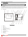


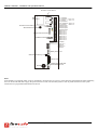
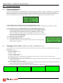


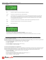
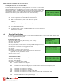

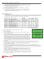


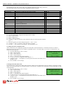
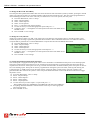


![G2 Decoder [obsolete] Second Generation User Manual](http://vs1.manualzilla.com/store/data/005963661_1-2c18e92993151caf68904a7a924089ff-150x150.png)

![AWD10SS [obsolete] User Manual](http://vs1.manualzilla.com/store/data/005777265_1-bc3e4afb4b891fb2fe3c32a930faa0e5-150x150.png)