1
Device for PV Plant Monitoring and Load Management
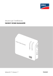
SUNNY HOME MANAGER
Installation Manual
HoMan-IA-IEN121212 | Version 1.2
EN
SMA Solar Technology AG
Table of Contents
Table of Contents
1
Information on this Manual. . . . . . . . . . . . . . . . . . . . . . . . . 6
2
2.1
2.2
2.3
Safety . . . . . . . . . . . . . . . . . . . . . . . . . . . . . . . . . . . . . . . . . . 9
Intended Use. . . . . . . . . . . . . . . . . . . . . . . . . . . . . . . . . . . . . . . . 9
Qualification of Skilled Persons . . . . . . . . . . . . . . . . . . . . . . . . 11
Safety Instructions . . . . . . . . . . . . . . . . . . . . . . . . . . . . . . . . . . . 12
3
3.1
3.2
3.3
3.4
Product Description . . . . . . . . . . . . . . . . . . . . . . . . . . . . . . 13
Sunny Home Manager . . . . . . . . . . . . . . . . . . . . . . . . . . . . . . . 13
LEDs of the Sunny Home Manager. . . . . . . . . . . . . . . . . . . . . . 17
SMA Radio-controlled Socket. . . . . . . . . . . . . . . . . . . . . . . . . . 18
LED Display of the SMA Radio-controlled Socket. . . . . . . . . . . 19
4
4.1
4.2
Scope of Delivery . . . . . . . . . . . . . . . . . . . . . . . . . . . . . . . . 21
Scope of Delivery of the Sunny Home Manager . . . . . . . . . . . 21
Scope of Delivery of SMA Radio-controlled Socket . . . . . . . . . 22
5
Preparing the Mounting and Commissioning of the
Sunny Home Manager . . . . . . . . . . . . . . . . . . . . . . . . . . . 23
6
6.1
6.4
Mounting. . . . . . . . . . . . . . . . . . . . . . . . . . . . . . . . . . . . . . . 25
Requirements of the Mounting Location of the
Sunny Home Manager . . . . . . . . . . . . . . . . . . . . . . . . . . . . . . . 25
Requirement of the Mounting Location of the
SMA Radio-controlled Socket. . . . . . . . . . . . . . . . . . . . . . . . . . 25
Checking the Bluetooth Connection at the Designated
Mounting Location . . . . . . . . . . . . . . . . . . . . . . . . . . . . . . . . . . 26
Mounting the Sunny Home Manager. . . . . . . . . . . . . . . . . . . . 27
6.4.1
Mounting the Sunny Home Manager on the Wall . . . . . . . . . . . . . . . . . . . . 27
6.4.2
Mounting the Sunny Home Manager on the Top-hat Rail . . . . . . . . . . . . . . 27
6.2
6.3
Installation Manual
HoMan-IA-IEN121212
3
Table of Contents
SMA Solar Technology AG
7
7.1
7.2
Connection . . . . . . . . . . . . . . . . . . . . . . . . . . . . . . . . . . . . . 28
Connection Area. . . . . . . . . . . . . . . . . . . . . . . . . . . . . . . . . . . . 28
Connecting Sunny Home Manager to Energy Meter . . . . . . . . 31
7.2.1
Connecting Sunny Home Manager to Energy Meter with
D0 Interface . . . . . . . . . . . . . . . . . . . . . . . . . . . . . . . . . . . . . . . . . . . . . . . . . 31
7.2.2
Connecting Sunny Home Manager to Energy Meter With
S0 Interface. . . . . . . . . . . . . . . . . . . . . . . . . . . . . . . . . . . . . . . . . . . . . . . . . . 32
7.3
7.4
Connecting the Sunny Home Manager to the Router. . . . . . . . 33
Supplying the Sunny Home Manager With Voltage . . . . . . . . 34
7.4.1
Supplying the Sunny Home Manager With Voltage via the Plug-in
Power Supply . . . . . . . . . . . . . . . . . . . . . . . . . . . . . . . . . . . . . . . . . . . . . . . . 34
7.4.2
Supplying the Sunny Home Manager With Voltage via the Top-hat
Rail Power Supply . . . . . . . . . . . . . . . . . . . . . . . . . . . . . . . . . . . . . . . . . . . . . 34
8
8.1
Commissioning . . . . . . . . . . . . . . . . . . . . . . . . . . . . . . . . . . 37
Preparing Bluetooth Communication . . . . . . . . . . . . . . . . . . . . 37
8.1.1
8.1.2
Configuring the NetID on the Sunny Home Manager . . . . . . . . . . . . . . . . . 37
Configuring the NetID on the SMA Radio-controlled Socket . . . . . . . . . . . . 38
8.2
8.3
8.4
Establishing Connection to the Sunny Portal . . . . . . . . . . . . . . . 38
Registering in the Sunny Portal . . . . . . . . . . . . . . . . . . . . . . . . . 39
Configuring the Operating Mode of the
SMA Radio-controlled Socket. . . . . . . . . . . . . . . . . . . . . . . . . . 44
9
9.1
Troubleshooting . . . . . . . . . . . . . . . . . . . . . . . . . . . . . . . . . 46
Error in the Sunny Home Manager. . . . . . . . . . . . . . . . . . . . . . 46
9.1.1
States of all LEDs. . . . . . . . . . . . . . . . . . . . . . . . . . . . . . . . . . . . . . . . . . . . . . 46
9.1.2
States of the Status LED. . . . . . . . . . . . . . . . . . . . . . . . . . . . . . . . . . . . . . . . . 46
9.1.3
States of the Bluetooth LED . . . . . . . . . . . . . . . . . . . . . . . . . . . . . . . . . . . . . . 49
9.2
9.3
Error in the SMA Radio-controlled Socket. . . . . . . . . . . . . . . . . 50
Error During Registration to Sunny Portal . . . . . . . . . . . . . . . . . 51
9.4
9.5
Using Sunny Home Manager Assistant . . . . . . . . . . . . . . . . . . 56
Error in the Sunny Home Manager Assistant . . . . . . . . . . . . . . 56
4
HoMan-IA-IEN121212
Installation Manual
SMA Solar Technology AG
9.6
9.7
9.8
10
10.1
10.2
10.3
Table of Contents
Resetting the Sunny Home Manager . . . . . . . . . . . . . . . . . . . . 57
Reassigning the Sunny Home Manager Plant After Resetting
the Sunny Home Manager . . . . . . . . . . . . . . . . . . . . . . . . . . . . 58
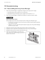
Resetting the SMA Radio-controlled Socket to Default Settings 59
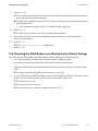
Decommissioning . . . . . . . . . . . . . . . . . . . . . . . . . . . . . . . . 60
Disassembling the Sunny Home Manager . . . . . . . . . . . . . . . . 60
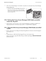
Packing the Sunny Home Manager/SMA Radio-controlled
Socket for Dispatch. . . . . . . . . . . . . . . . . . . . . . . . . . . . . . . . . . 61
Disposal of the Sunny Home Manager/SMA Radio-controlled
Socket . . . . . . . . . . . . . . . . . . . . . . . . . . . . . . . . . . . . . . . . . . . . 61
11
11.1
11.2
11.3
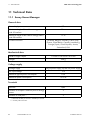
Technical Data . . . . . . . . . . . . . . . . . . . . . . . . . . . . . . . . . . 62
Sunny Home Manager . . . . . . . . . . . . . . . . . . . . . . . . . . . . . . . 62
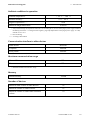
SMA Radio-controlled Socket. . . . . . . . . . . . . . . . . . . . . . . . . . 64
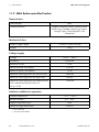
Plug-in Power Supplies . . . . . . . . . . . . . . . . . . . . . . . . . . . . . . . 65
11.3.1
TaiyTech, TYT251200200UV/3000M . . . . . . . . . . . . . . . . . . . . . . . . . . . . 65
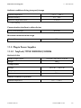
11.3.2
TaiyTech, TYT251200200EU/3000M . . . . . . . . . . . . . . . . . . . . . . . . . . . . 66
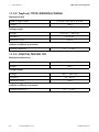
11.3.3
CINCON, TRG30R 120. . . . . . . . . . . . . . . . . . . . . . . . . . . . . . . . . . . . . . . . 66
12
Accessories . . . . . . . . . . . . . . . . . . . . . . . . . . . . . . . . . . . . . 67
13
Software Licenses. . . . . . . . . . . . . . . . . . . . . . . . . . . . . . . . 68
14
Contact . . . . . . . . . . . . . . . . . . . . . . . . . . . . . . . . . . . . . . . . 69
Installation Manual
HoMan-IA-IEN121212
5
1 Information on this Manual
1
SMA Solar Technology AG
Information on this Manual
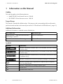
Validity
This manual applies to the following devices:
• HM-BT-10.GR1 from firmware version 1.00.0.R
• BT-SOCKET-10 from firmware version 1.00.0.R
Target Group
This manual is intended for skilled workers. Only persons with corresponding skills are allowed to
perform the tasks set forth in this manual (see section 2.2 "Qualification of Skilled Persons", page 11).
Additional Information
Additional information is available at www.SMA.de/en:
Document Title
Document Type
®
SMA Bluetooth – SMA Bluetooth Wireless
Technology in practice
Technical Information
SMA Bluetooth® Wireless Technology
Technical Description
Symbols
Symbol
Explanation
Indicates a hazardous situation which, if not avoided, will result in death
or serious injury.
Indicates a hazardous situation which, if not avoided, could result in death
or serious injury.
Indicates a hazardous situation which, if not avoided, could result in minor
or moderate injury.
Indicates a situation that can result in property damage if not avoided.
Indicates information that is important for a specific topic or objective,
but is not safety-relevant.
6
☐
Indicates a requirement for meeting a specific goal.
☑
Desired result.
✖
A problem that could occur.
HoMan-IA-IEN121212
Installation Manual
SMA Solar Technology AG
1 Information on this Manual
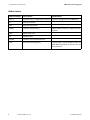
Typography
Typography
Usage
"light"
Example
• Inverter display messages
• Elements in a software
user interface
• The value can be read in
the "Energy" field.
• Terminals
bold
• Elements that are to be
selected
• Enter 10 in the "Minutes"
field.
>
• Several elements that are
to be selected
• Select Settings > Date.
[Button/key]
• Button or key to be
selected or pressed
• Select [Next].
Nomenclature
The following nomenclature is used in this manual:
Complete designation
Short form in the manual
SMA Bluetooth® Piggy-Back,
SMA Bluetooth® Piggy-Back Plus
Bluetooth Piggy-Back
SMA Bluetooth® Piggy-Back Offgrid
Bluetooth Piggy-Back Offgrid
®
SMA Bluetooth Repeater,
SMA Bluetooth® Repeater Outdoor
Bluetooth Repeater
Sunny WebBox, Sunny WebBox with
Bluetooth® Wireless Technology
Sunny WebBox
SMA Bluetooth® Wireless Technology
Bluetooth
SMA radio-controlled socket with
Bluetooth® Wireless Technology
SMA radio-controlled socket
Installation Manual
HoMan-IA-IEN121212
7
1 Information on this Manual
SMA Solar Technology AG
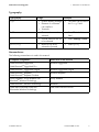
Abbreviations
8
Abbreviations
Description
DHCP
Dynamic Host Configuration Protocol Dynamic assignment of IP addresses
IP
Internet Protocol
-
LED
Light-Emitting Diode
-
NetID
Network Identification
Identification number for SMA Bluetooth
network
MSL
Mean Sea Level
-
PV
Photovoltaics
-
WLAN
Wireless Local Area Network
-
PUK
Personal Unlocking Key
Code number, which enables access to
SMA Bluetooth devices, after the loss of
the password
HoMan-IA-IEN121212
Explanation
Installation Manual
SMA Solar Technology AG
2
2 Safety
Safety
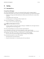
2.1 Intended Use
Sunny Home Manager
The Sunny Home Manager is a device for monitoring PV plants and for managing loads in
households with PV plants. For this purpose, the Sunny Home Manager carries out the following tasks:
• Reading out energy meter data and data from SMA inverters with Bluetooth communication
interfaces
• Sending data to the Sunny Portal
• Providing support in increasing the self-consumption rate
The Sunny Home Manager is not splash-proof.
• Only use the Sunny Home Manager indoors.
Additional information for France
In France, outdoor use of the Sunny Home Manager is forbidden due to the legal restrictions
regarding Bluetooth transmitting power.
The Sunny Home Manager must only be used with supported devices.
It is not permitted to convert the Sunny Home Manager or install component parts.
Only use the Sunny Home Manager in accordance with the information provided in the enclosed
documentation. Any other use can result in personal injury or property damage.
• Do not use the Sunny Home Manager in plants including a Sunny WebBox.
The enclosed documentation is a part of this product.
• Read and observe the documentation.
• Keep the documentation in a convenient place for future reference.
Installation Manual
HoMan-IA-IEN121212
9
2 Safety
SMA Solar Technology AG
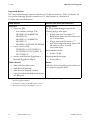
Supported devices
The Sunny Home Manager supports a maximum of 16 Bluetooth devices. Of the 16 devices, the
Sunny Home Manager supports a maximum of 12 SMA inverters or a maximum of
10 SMA radio-controlled sockets.
SMA devices
Devices from other manufacturers
Inverters:
Energy meter:
• Sunny Boy (SB):
– From software package 2.06:
SB 3000TL-20, SB 4000TL-20,
SB 5000TL-20
– SB 3000TL-21, SB 4000TL-21,
SB 5000TL-21
– SB 2000HF, SB 2500HF, SB 3000HF
• Sunny Tripower (STP):
– STP 8000TL-10, STP 10000TL-10,
STP 12000TL-10, STP 15000TL-10,
STP 17000TL-10
• Inverters with Bluetooth Piggy-Back or
Bluetooth Piggy-Back Offgrid*
Other devices:
• SMA radio-controlled socket
• SMA Bluetooth Repeater
The Sunny Home Manager supports the
following energy meter types:
• Energy meter with S0 interface:**
Bidirectional meters with S0 interface must
use 2 S0 interfaces.
• Energy meter with D0 interface:***
A list of the supported energy meters with
D0 interface can be found at
www.SMA.de/en.
Recommended solution:
• At least 10 Wh
Recommended pulse length:
• At least 20 ms
Router:
SMA Solar Technology AG recommends the use
of a router that supports DHCP.
• SMA Bluetooth Repeater Outdoor
• Sunny SensorBox with SMA Power Injector
with Bluetooth.
* A list of these inverters can be found in the manual of the corresponding Bluetooth Piggy-Back or the
Bluetooth Piggy-Back Offgrid.
** S0 interface according to DIN EN 62053-31 class A
*** D0 interface according to IEC 62056-21, part 4.3
10
HoMan-IA-IEN121212
Installation Manual
SMA Solar Technology AG
2 Safety
SMA radio-controlled socket
The SMA radio-controlled socket supports load management in households with Sunny Home
Manager. For this purpose, the SMA radio-controlled socket carries out the following tasks:
• Converting control commands of Sunny Home Manager
• Measuring the energy consumption of the connected electrical load
• Improving the wireless connection between Bluetooth devices
The SMA radio-controlled socket is not splash-proof.
• Only use the SMA radio-controlled socket indoors.
Additional information for France
In France, outdoor use of the SMA radio-controlled socket is forbidden due to the legal
restrictions regarding Bluetooth transmitting power.
It is not permitted to convert the SMA radio-controlled socket or install component parts, as the
conversion or the installation of component parts can lead to property damage or injury.
Only use the SMA radio-controlled socket in accordance with the information provided in the
enclosed documentation. Any other use can result in personal injury or property damage.
• Do not connect any medical devices to the SMA radio-controlled socket.
• Do not connect any loads to the SMA radio-controlled socket that require a continuous supply
of current (e.g. refrigerator, freezer).
• Do not connect any loads to the SMA radio-controlled socket that can cause injuries or fires if
unintentionally switched on (e.g. iron).
• Only connect loads to the SMA radio-controlled socket that are suitable for the voltage and
power range of the SMA radio-controlled socket (see section 11.2 "SMA Radio-controlled
Socket", page 64).
• Only connect the SMA radio-controlled socket to socket-outlets with a protective contact in
standard installation.
The enclosed documentation is a part of this product.
• Read and observe the documentation.
• Keep the documentation in a convenient place for future reference.
2.2 Qualification of Skilled Persons
The tasks described in this manual are intended for skilled persons only. Skilled persons must have the
following qualifications:
• Training in the installation and commissioning of electrical devices.
• Knowledge of all applicable standards and guidelines.
Installation Manual
HoMan-IA-IEN121212
11
2 Safety
SMA Solar Technology AG
2.3 Safety Instructions
Sunny Home Manager
Risk of lethal electric shock
Lethal voltages are present at the conductive parts inside the plug-in power supply and at the
conductive parts of the top-hat rail power supply.
• Only use the Sunny Home Manager indoors and in a dry environment, keeping it away from
liquids.
• Do not open the plug-in power supply.
Risk of injury due to incorrect cable routing
Incorrectly routed cables can cause injuries due to tripping.
• Route the cables in such a way that no one can stand on or trip over them.
Damage to the Sunny Home Manager due to moisture penetration
The Sunny Home Manager is not splash-proof.
• Only use the Sunny Home Manager indoors and in a dry environment.
SMA radio-controlled socket
Risk of lethal electric shock
Lethal voltages are present at the conductive component parts.
• Only use the SMA radio-controlled socket indoors and in a dry environment (e.g. not in damp
rooms) and keep away from liquids.
• Only insert suitable plugs into the SMA radio-controlled socket.
• Unplug the SMA radio-controlled socket from the socket-outlet prior to cleaning and only clean
with a dry cloth.
Risk of injury and fire due to unintentional and unattended switching on of loads
Loads that are subject to unintentional and unattended switching on via an SMA radio-controlled
socket can cause injuries and fires (e.g. iron).
• Do not connect any loads to the SMA radio-controlled socket that endanger persons or can
cause damage in the event of unintentional switching on.
12
HoMan-IA-IEN121212
Installation Manual
SMA Solar Technology AG
3
3 Product Description
Product Description
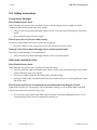
3.1 Sunny Home Manager
The Sunny Home Manager is a device for monitoring PV plants and for managing loads in
households with PV plants. For this purpose, the Sunny Home Manager carries out the following tasks:
• Reading out energy meter data and data from Bluetooth devices
• Sending data to the Sunny Portal
• Providing support in increasing the self-consumption rate
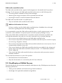
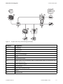
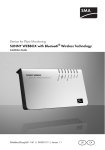
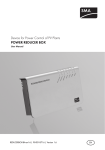
Figure 1:
Sunny Home Manager
Position
Designation
A
Status LED and energy consumption LED
B
USB port*
Connection area with Bluetooth LED
C
* The USB ports on the right and left sides of the enclosure do not currently have a function.
Reading out energy meter data and data from Bluetooth devices
The Sunny Home Manager reads the data of the connected energy meter and Bluetooth devices. The
Sunny Home Manager establishes the connection to the Bluetooth devices wirelessly via Bluetooth.
The Sunny Home Manager is connected to the energy meters via cables.
Sending data to the Sunny Portal
The Sunny Portal is the user interface of the Sunny Home Manager. The Sunny Home Manager sends
the data read out to the Sunny Portal. The Sunny Home Manager establishes the connection to the
Sunny Portal via a router.
Installation Manual
HoMan-IA-IEN121212
13
3 Product Description
SMA Solar Technology AG
Providing support in increasing the self-consumption rate
Self-consumption means the consumption of PV power produced at the site of your generation.
In every household, there is "natural" self-consumption as electrical loads are operated while PV
power is produced (e.g. oven) and because certain electrical loads consume current continuously
(e.g. refrigerator, devices in standby mode). If the PV plant produces a lot of PV power, it is possible
that only a part of the PV power will be self-consumed. The residual PV power is fed into the power
distribution grid.
A higher self-consumption rate can be achieved if electrical loads are specifically switched on when
residual PV power is available.
The following functions of the Sunny Home Manager make it possible to increase the
self-consumption rate:
Function
Explanation
Creating a generation
prognosis
The Sunny Home Manager receives location-based weather forecasts via
the internet and uses them to create generation prognoses for the PV plant.
Creating a load profile The Sunny Home Manager detects how much energy is typically
consumed at certain times in a household and uses this to create a load
profile of the household.
To create the load profile, the following energy meters must be connected
to the Sunny Home Manager:
• Feed-in meter and consumption meter
or
Bidirectional meter for grid feed-in and purchased electricity
Controlling SMA radio- Specific electrical loads connected to SMA radio-controlled sockets can
controlled sockets
be switched on and off by the Sunny Home Manager. For this purpose,
the Sunny Home Manager uses the generation prognosis and the load
profile to determine favorable points in time for increasing the selfconsumption rate.
Sending energy meter
data to Sunny Backup
systems
If a Bluetooth Piggy-Back Offgrid is installed in the Sunny Backup, the
Sunny Home Manager can send the energy meter data to the
Sunny Backup system.
At a suitable point in time, the Sunny Backup activates the charge of
electric discharge of the batteries:
• If residual PV power is available, this is stored in the batteries.
• If no PV power is available, the Sunny Backup activates the electric
discharge of the batteries and the energy can be used.
14
HoMan-IA-IEN121212
Installation Manual
SMA Solar Technology AG
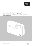
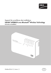
Figure 2:
3 Product Description
PV plant with Sunny Home Manager (Example)
Position
Designation
A
PV modules
B
Sunny Portal
C
PV inverter
D
Sunny Home Manager
E
Router
F
PV production meter
G
Feed-in meter and consumption meter or bidirectional meter for grid feed-in and
purchased electricity
H
Power distribution grid
I
Sunny Backup
K
SMA radio-controlled socket
L
Battery
M
Electrical load
Installation Manual
HoMan-IA-IEN121212
15
3 Product Description
SMA Solar Technology AG
System requirements
Operating systems supported by the Sunny Home Manager Assistant:
• Microsoft Windows 7
• Microsoft Windows Vista
• Microsoft Windows XP Service Pack 2
• Linux with kernel from version 2.6.12, KDE, with Oracle Java Runtime Environment from
version 6
• MAC OS from version 10.6, with Java Runtime Environment from version 6
Internet access requirements:
• Permanent internet access. Recommended: DSL access with flat rate
Supported web browsers:
• Google Chrome from version 14.0
• Microsoft Internet Explorer from version 8
• Mozilla Firefox from version 5
• Opera from version 11.0
• Safari from version 5.0
Recommended screen resolution:
• Minimum 1024 pixels x 768 pixels
Energy meter:
SMA Solar Technology AG recommends connecting at least the following energy meter types to the
Sunny Home Manager:
• Feed-in meter and consumption meter
or
• Bidirectional meter for grid feed-in and purchased electricity
Type label
You can identify the Sunny Home Manager using the type label. The type label can be found on the
rear of the Sunny Home Manager. You can read out the following data from the type label:
• Serial number
• Registration ID
• Assembly name
• Hardware version
16
HoMan-IA-IEN121212
Installation Manual
SMA Solar Technology AG
3 Product Description
3.2 LEDs of the Sunny Home Manager
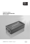
Figure 3:
LEDs of the Sunny Home Manager
Position
Designation
Explanation
A
Energy consumption LED
Displays the momentary current consumption.
B
Status LED
Displays the current status of the
Sunny Home Manager.
C
Bluetooth LED
Displays the status of the Bluetooth connection.
Energy consumption LED
The energy consumption LED is only active when either the bidirectional meter for grid feed-in and
purchased electricity or the feed-in meter and the consumption meter are connected.
LED Status
Explanation
Glows green
The household only receives energy from the PV plant.
Flashing green and
orange intermittently
The household receives energy from the PV plant and from the power
distribution grid.
Glows orange
The household only receives current from the power distribution grid.
Status LED
LED Status
Explanation
Glows green
The Sunny Home Manager is connected to the Bluetooth devices and the
Sunny Portal.
Further states of the status LED are described in the section "Troubleshooting"
(see section 9.1.2 "States of the Status LED", page 46).
Installation Manual
HoMan-IA-IEN121212
17
3 Product Description
SMA Solar Technology AG
Bluetooth LED
LED Status
Explanation
Glows blue
The Bluetooth connection to the devices of the PV plant is good.
Further states of the Bluetooth LED are described in the section "Troubleshooting"
(see section 9.1.3 "States of the Bluetooth LED", page 49).
3.3 SMA Radio-controlled Socket
The SMA radio-controlled socket supports load management in households with Sunny Home Manager.
For this purpose, the SMA radio-controlled socket carries out the following tasks:
• Converting control commands of Sunny Home Manager
• Measuring the energy consumption of the connected electrical load
• Improving the wireless connection between Bluetooth devices
Converting control commands of Sunny Home Manager
The Sunny Home Manager can switch the SMA radio-controlled socket on and off. As a result,
specific electrical devices can be switched on if e.g. a lot of PV power is available.
The points in time at which the Sunny Home Manager switches the radio-controlled socket on or off
depends on the configuration of the SMA radio-controlled socket
(see user manual "Sunny Home Manager in the Sunny Portal").
Measuring the energy consumption of the connected electrical load
The SMA radio-controlled socket measures the energy consumption of the connected electrical loads.
Improving the wireless connection between Bluetooth devices
If the distance between Bluetooth devices is too great or obstructions interfere with the Bluetooth
connection, the SMA radio-controlled socket can be used as a repeater. As a result, the dead zone
is closed.
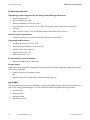
Figure 4:
18
SMA radio-controlled socket
HoMan-IA-IEN121212
Installation Manual
SMA Solar Technology AG
3 Product Description
Position
Designation
Explanation
A
LED display
• Displays status, operating modes, and NetIDs.
B
Touch key
• Operation of the SMA radio-controlled socket
Type label
You can identify the SMA radio-controlled socket using the type label. The type label can be found
on the rear of the SMA radio-controlled socket. You can read out the following data from the type
label:
• Serial number
• Assembly name
• Hardware version
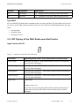
3.4 LED Display of the SMA Radio-controlled Socket
Upper horizontal LED
Figure 5:
Upper horizontal LED of the LED display
LED Status
Operating Mode/Status of the SMA Radio-controlled Socket
Glows green
"Manually switched on". SMA radio-controlled socket not controlled by
the Sunny Home Manager.
Glows orange
"Manually switched off". SMA radio-controlled socket not controlled by
the Sunny Home Manager.
Flashes green
"Automatically switched on". SMA radio-controlled socket controlled by
the Sunny Home Manager.
Flashes orange
"Automatically switched off". SMA radio-controlled socket controlled by
the Sunny Home Manager.
Glows red
System starts.
or
Update process runs.
In this status, do not unplug the SMA radio-controlled socket from the
socket-outlet. Otherwise, the SMA radio-controlled socket could be
damaged.
Installation Manual
HoMan-IA-IEN121212
19
3 Product Description
SMA Solar Technology AG
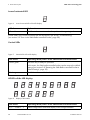
Lower horizontal LED
Figure 6:
Lower horizontal LED of the LED display
LED Status
Explanation
Glows blue
The Bluetooth connection to the Sunny Home Manager is good.
Further states of the lower horizontal LED are described in the section "Troubleshooting"
(see section 9.2 "Error in the SMA Radio-controlled Socket", page 50).
Vertical LEDs
Figure 7:
Vertical LEDs of the LED display
LED Status
Operating Mode/Status of the SMA Radio-controlled Socket
Glows green
The touch key is ready for operation.
In this status, the SMA radio-controlled socket can be reset to the default
settings (see section 9.8 "Resetting the SMA Radio-controlled Socket to
Default Settings", page 59).
Flashes green
The SMA radio-controlled socket is initialized.
All LEDs of the LED display
Figure 8:
Display of the NetIDs
LED Status
Operating Mode/Status of the SMA Radio-controlled Socket
0, 2 … 9 and A … F
NetID configuration mode and display of the configured NetID
20
HoMan-IA-IEN121212
Installation Manual
SMA Solar Technology AG
4
4 Scope of Delivery
Scope of Delivery
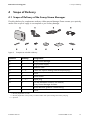
4.1 Scope of Delivery of the Sunny Home Manager
Check the delivery for completeness and any visible external damage. Please contact your specialty
retailer if the scope of supply is not complete or you find any damage.
Figure 9:
Components included in delivery
Position
Quantity
Designation
A
1
Sunny Home Manager
B
1
Plug-in power supply
C
1
Network cable
D
0 … 2*
Cable with optical reading head and 4-pole plug***
E
2
Screw
F
2
Screw anchor
G
1 … 3**
4-pole plug
H
1
CD with installation manual, user manual,
Sunny Home Manager Assistant
I
1
Quick reference guide for commissioning
K
6
Sticker
* Quantity dependent on order
** Quantity dependent on the quantity of ordered cables with optical reading head and 4-pole plug
*** Optional
Installation Manual
HoMan-IA-IEN121212
21
4 Scope of Delivery
SMA Solar Technology AG
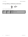
4.2 Scope of Delivery of SMA Radio-controlled Socket
Figure 10: Components included in delivery
Position
Quantity
Designation
A
1
SMA radio-controlled socket
B
1
User Manual
22
HoMan-IA-IEN121212
Installation Manual
SMA Solar Technology AG
5
5 Preparing the Mounting and Commissioning of the Sunny Home Manager
Preparing the Mounting and Commissioning of the
Sunny Home Manager
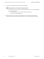
1.
Damage to the Sunny Home Manager due to condensation water
If the Sunny Home Manager is taken from a cold environment into a warm environment,
condensation water may form in the Sunny Home Manager.
• In the event of large temperature differences, only supply the Sunny Home Manager with
voltage once the Sunny Home Manager has reached room temperature.
2. If another plant with Bluetooth is located within 500 m of your plant, detect a free NetID at the
planned mounting location of every Bluetooth device.
Requirement for detecting a free NetID
You can only detect a free NetID using a computer with integrated Bluetooth or with
Bluetooth stick (Bluetooth class 1) and the software Sunny Explorer (see Sunny Explorer
help). You can obtain the Sunny Explorer for free in the download area of
www.SMA.de/en.
3. With the exception of the Sunny Home Manager and the SMA radio-controlled socket,
configure the same NetID for all Bluetooth devices. For this purpose, configure a NetID from
1 … 9 or A … F (see manual of the Bluetooth devices or the Bluetooth Piggy-Back).
Requirement for configuring NetID 1
For Bluetooth devices, NetID 1 is preset at the factory. You may only configure NetID 1
if your Bluetooth PV plant consists of a maximum of one inverter and one
Sunny Home Manager.
• If the PV plant consists of more Bluetooth devices than one inverter and one
Sunny Home Manager, configure a different NetID as NetID 1.
4. Note down the serial numbers of the Sunny Home Manager and all other Bluetooth devices.
For the SMA radio-controlled sockets, also note down the load that you wish to allocate to the
respective radio-controlled socket.
Installation Manual
HoMan-IA-IEN121212
23
5 Preparing the Mounting and Commissioning of the Sunny Home Manager
SMA Solar Technology AG
5. Note down the registration ID of the Sunny Home Manager.
Reading out the serial number and registration ID
You can read out the serial number and the registration ID of the Sunny Home Manager
at the following locations:
• On the type label on the rear of the Sunny Home Manager
• On the cover of the supplied CD
6. With the exception of the Sunny Home Manager and the SMA radio-controlled socket,
commission all Bluetooth devices (see manual of the inverters and the Bluetooth devices).
24
HoMan-IA-IEN121212
Installation Manual
SMA Solar Technology AG
6
6 Mounting
Mounting
6.1 Requirements of the Mounting Location of the
Sunny Home Manager
☐ The mounting location is indoors.
☐ The mounting location is protected against dust, moisture, and corrosive substances.
☐ The cable route from the mounting location to the router is a maximum of 100 m in length.
☐ The cable route from the mounting location of the Sunny Home Manager to the energy meters
with D0 interface is a maximum of 15 m in length.
☐ The cable route from the mounting location of the Sunny Home Manager to the energy meters
with S0 interface is a maximum of 30 m in length.
☐ The distance to devices that use the 2.4 GHz frequency band (e.g. WLAN devices,
microwaves), must be at least 1 m. As a result, you avoid reductions in the connection quality
and the data transmission speed.
☐ The Sunny Home Manager does not have radio shielding (e.g. in a metal cabinet).
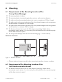
50 mm
Minimum clearances:
SUNNY HOME MANAGER
70 mm
50 mm
150 mm
70 mm
Figure 11: Minimum clearances
• Observe minimum clearances to walls, other communication products, inverters, or objects.
6.2 Requirement of the Mounting Location of the
SMA Radio-controlled Socket
☐ The distance to devices that use the 2.4 GHz frequency band (e.g. WLAN devices,
microwaves), must be at least 1 m. As a result, you avoid reductions in the connection quality
and the data transmission speed.
Installation Manual
HoMan-IA-IEN121212
25
6 Mounting
SMA Solar Technology AG
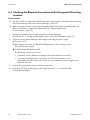
6.3 Checking the Bluetooth Connection at the Designated Mounting
Location
Requirements:
☐ The same NetID is configured for all Bluetooth devices (see section 5 "Preparing the Mounting
and Commissioning of the Sunny Home Manager", page 23).
☐ With the exception of the Sunny Home Manager and the SMA radio-controlled socket, the
Bluetooth PV plant is commissioned (see section 8.1 "Preparing Bluetooth
Communication", page 37).
1. Configure the NetID of the PV plant on the Sunny Home Manager
(see section 8.1.1 "Configuring the NetID on the Sunny Home Manager", page 37).
2. Supply the Sunny Home Manager with voltage via the plug-in power supply
(see section 7.4.1).
☑ After approx. 2 minutes, the Bluetooth LED glows blue. The connection to the
Bluetooth devices is good.
✖ Is the Bluetooth LED flashing blue?
The Bluetooth connection is critical.
• If possible, select a different mounting location and check the connection.
• If no other mounting location is possible, use a Bluetooth repeater or an
SMA radio-controlled socket. As a result, you can extend the wireless range of your
Bluetooth network.
3. Unplug the plug-in power supply from the socket-outlet.
4. Unplug the DC plug of the plug-in power supply from the "Power" terminal of the
Sunny Home Manager.
26
HoMan-IA-IEN121212
Installation Manual
SMA Solar Technology AG
6 Mounting
6.4 Mounting the Sunny Home Manager
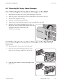
6.4.1 Mounting the Sunny Home Manager on the Wall
1. Determine the location of the Sunny Home Manager on the wall.
2. Mark the position of the drill holes on the wall (distance of drill holes: 58 mm).
3. Drill the holes (diameter: 6 mm).
4. Insert the screw anchors into the holes.
5. Screw in the screws and leave approx. 6 mm protruding from the wall.
6. Hang the Sunny Home Manager on the screws. In
the process, ensure that the heads of the screws are
engaged in the holes on the rear of the
Sunny Home Manager.
6.4.2 Mounting the Sunny Home Manager on the Top-hat Rail
Requirement:
☐ The top-hat rail is securely mounted on the wall.
1. Press the Sunny Home Manager with the upper
retainers into the upper edge of the top-hat rail.
2. Hook the lower retainers into the lower edge of the
top-hat rail.
Installation Manual
HoMan-IA-IEN121212
27
7 Connection
7
SMA Solar Technology AG
Connection
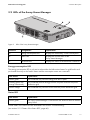
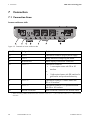
7.1 Connection Area
Lower enclosure side
Figure 12: Terminals on lower enclosure side
Position
Designation
Explanation
A
"Power"
Connection socket for plug-in power supply
B
"NetID"
Rotary switch for configuring the NetID
C
Bluetooth LED
Status display of Bluetooth connection
D
"Meter 1"
Connection socket for:
• 1 consumption meter with D0 or S0
interface
or
• 1 bidirectional meter with D0 interface for
grid feed-in and purchased electricity
E
"Meter 2"
Connection socket for 1 feed-in meter with
D0 or S0 interface*
F
"Meter 3"
Connection socket for 1 PV production meter
with D0 or S0 interface
G
Ethernet connection
RJ45 connection socket for the network cable
* When connecting a bidirectional meter to the connection socket "Meter 1", the connection socket "Meter 2" does not have
a function.
28
HoMan-IA-IEN121212
Installation Manual
SMA Solar Technology AG
7 Connection
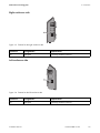
Right enclosure side
Figure 13: Terminal on the right enclosure side
Position
Designation
Explanation
A
USB port
Currently without function.
Left enclosure side
Figure 14: Terminal on the left enclosure side
Position
Designation
Explanation
A
USB port
Currently without function.
Installation Manual
HoMan-IA-IEN121212
29
7 Connection
SMA Solar Technology AG
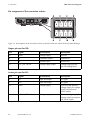
Pin assignment of the connection sockets
Figure 15: Pin assignment of the connection sockets on the lower enclosure side of the Sunny Home Manager
Upper pin row for D0:
Pin
Signal
Specification
Description
A
GND
Voltage supply
Ground
B
TX
Transmitter output
Transmit D0
C
RX
Receiver input
Receive D0
D
VCC_D0, +8 volt
Voltage supply output
Voltage supply for the
optical reading head
Lower pin row for S0:
Pin
Signal
Specification
Description
E
S0-
Input and output
S0 signal
F
S0+
Input and output
S0 signal
G
GND
Voltage supply
Ground of the external
voltage supply for voltage
supply via top-hat rail
power supply
H
+12 volt, DC
Voltage supply input
External voltage supply for
voltage supply via top-hat
rail power supply
30
HoMan-IA-IEN121212
Installation Manual
SMA Solar Technology AG
7 Connection
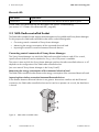
7.2 Connecting Sunny Home Manager to Energy Meter
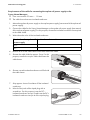
7.2.1 Connecting Sunny Home Manager to Energy Meter with
D0 Interface
Additional required material (not included in scope of delivery):
☐ Cable with reading head and 4-pole plug (see section 11.3.3 "CINCON, TRG30R
120", page 66).
1. Place the magnet retainer of the reading head on
the upper right of the front side of the energy meter.
For this purpose, the infrared interfaces on the
reading head and the energy meter must rest of top
of one another.
2. Connect the plug of the reading head to the
connection socket to which the corresponding
energy meter is allocated. For this purpose, insert
the 4-pole plug into the upper pin row:
• For consumption meters, insert the 4-pole plug
into the connection socket "Meter 1".
• For feed-in meters, insert the 4-pole plug into the
connection socket "Meter 2".
• For PV production meters, insert the 4-pole plug
into the connection socket "Meter 3".
• For bidirectional meters for grid feed-in and purchased electricity, insert the 4-pole plug into
the connection socket "Meter 1".
3. Use the stickers provided on every cable to identify which connection socket and which energy
meter the cable is assigned to.
Installation Manual
HoMan-IA-IEN121212
31
7 Connection
SMA Solar Technology AG
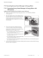
7.2.2 Connecting Sunny Home Manager to Energy Meter With
S0 Interface
Additional required material (not included in scope of delivery):
☐ A cable with at least two insulated conductors
Cable requirements:
☐ Core cross-section: 0.2 mm2 … 1.5 mm2
☐ Maximum cable length: 30 m
1. Remove 4 cm of cable sleeve.
2. Shorten the cable shield to approx. 5 mm. For this
purpose, transfer the surplus cable shield onto the
cable sleeve.
3. Shorten unused insulated conductors until flush with
the cable sleeve.
4. Strip approx. 6 mm of insulation off the insulated
conductors.
1
5. Unlock the jacks of the 4-pole plug with a
screwdriver. For this purpose, insert the insulated
conductors into pins 1 and 2 of the 4-pole plug.
6. Write down the color of the insulated conductors.
32
HoMan-IA-IEN121212
Installation Manual
SMA Solar Technology AG
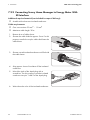
7 Connection
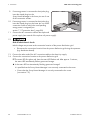
7. Connect the 4-pole plug to the connection socket to
which the corresponding energy meter is assigned.
For this purpose, correspondingly insert the 4-pole
plug into the lower pin row:
• For consumption meters, insert the 4-pole plug
into the connection socket "Meter 1".
• For feed-in meters, insert the 4-pole plug into the
connection socket "Meter 2".
• For PV production meters, insert the 4-pole plug
into the connection socket "Meter 3".
• For bidirectional meters for grid feed-in and purchased electricity, insert the connection plug
of the cable for purchased electricity into the connection socket "Meter 1". Insert the
connection plug of the cable for grid feed-in into the connection socket "Meter 2".
8. Connect the end of the cable to the energy meter. In the process, observe the polarity of the
insulated conductors.
9. Use the stickers provided on every cable to identify which connection socket and which energy
meter the cable is assigned to.
10. Write down the S0 pulses per kWh and the meter status of every energy meter. In this way, you
facilitate the meter configuration in the Sunny Portal.
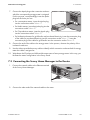
7.3 Connecting the Sunny Home Manager to the Router
1. Connect the network cable to the Ethernet terminal
of the Sunny Home Manager.
2. Connect the other end of the network cable to the router.
Installation Manual
HoMan-IA-IEN121212
33
7 Connection
SMA Solar Technology AG
7.4 Supplying the Sunny Home Manager With Voltage
7.4.1 Supplying the Sunny Home Manager With Voltage via the
Plug-in Power Supply
1. Connect the DC plug of the plug-in power supply to the connection socket "Power" of the
Sunny Home Manager.
2. Insert the plug-in power supply into the socket-outlet.
☑ The status LED of the Sunny Home Manager first glows red, then the status LED flashes red.
After approx. 2 minutes, the status LED intermittently flashes green and orange.
The Sunny Home Manager is connected to the Sunny Portal.
✖ Is the status LED not intermittently flashing green and orange?
It is possible that the Sunny Home Manager is not correctly connected to the router.
• Ensure that the Sunny Home Manager is correctly connected to the router
(see section 7.3).
7.4.2 Supplying the Sunny Home Manager With Voltage via the
Top-hat Rail Power Supply
As an alternative to the plug-in power supply, you can supply the Sunny Home Manager with voltage
using a top-hat rail power supply.
Additional required material (not included in scope of delivery):
☐ Top-hat rail power supply
☐ An AC connection cable
☐ A cable for connecting the top-hat rail power supply to the Sunny Home Manager
Top-hat rail power supply requirements:
☐ Output voltage DC: 12 V (tolerance: ± 10%)
☐ Nominal current: 1.5 A
34
HoMan-IA-IEN121212
Installation Manual
SMA Solar Technology AG
7 Connection
Requirements of the cable for connecting the top-hat rail power supply to the
Sunny Home Manager:
☐ Core cross-section: 0.2 mm2 … 1.5 mm2
☐ The cable has at least two insulated conductors
1. Mount the top-hat rail power supply on the top-hat power supply (see manual of the top-hat rail
power supply).
2. Connect the cable for the Sunny Home Manager to the top-hat rail power supply (see manual
of the top-hat rail power supply). For this purpose, shorten the insulated conductors not required
to the cable shield.
3. Write down the color of the insulated conductors:
Terminals on the top-hat rail Insulated conductor color
power supply
DC +
DC −
4. Remove 4 cm of the cable sleeve at the other end of the cable.
5. Shorten the cable shield to approx. 5 mm. For this
purpose, transfer the surplus cable shield onto the
cable sleeve.
6. Shorten unused insulated conductors until flush with
the cable sleeve.
7. Strip approx. 6 mm of insulation off the insulated
conductors.
8. Unlock of the jacks of the 4-pole plug with a
screwdriver. For this purpose, insert the DC −
insulated conductors into pin 3 and insert the DC +
insulated conductors into pin 4 of the 4-pole plug.
Installation Manual
HoMan-IA-IEN121212
35
7 Connection
SMA Solar Technology AG
9. If no energy meter is connected to the 4-pole plug,
insert the 4-pole plug into the
Sunny Home Manager in the lower pin row of one
of the connection sockets.
10. If an energy meter is connected to the 4-pole plug,
insert the 4-pole plug into the lower pin row of the
connection socket to which the corresponding
energy meter is assigned (see
section 7.1 "Connection Area", page 28).
Mete
r1
D
Mete
r2
Mete
r3
S
11. Connect the AC connection cable to the top-hat rail
power supply (see manual of the top-hat rail power supply).
12.
Risk of lethal electric shock
Lethal voltages are present at the connection location of the power distribution grid.
• Disconnect the connection location from the power distribution grid using the separator
(e.g. distribution board).
13. Connect the other end of the AC connection cable to the electricity supply.
14. Connect the connection location to the power distribution grid.
☑ The status LED first glows red, then the status LED flashes red. After approx. 2 minutes,
the status LED intermittently flashes green and orange.
✖ Is the status LED not intermittently flashing green and orange?
It is possible that the Sunny Home Manager is not correctly connected to the router.
• Ensure that the Sunny Home Manager is correctly connected to the router
(see section 7.3).
36
HoMan-IA-IEN121212
Installation Manual
SMA Solar Technology AG
8
8 Commissioning
Commissioning
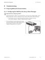
8.1 Preparing Bluetooth Communication
8.1.1 Configuring the NetID on the Sunny Home Manager
Requirement for configuring NetID 1
For Bluetooth devices, NetID 1 is preset at the factory. You may only configure NetID 1 if your
Bluetooth PV plant consists of a maximum of one inverter and one Sunny Home Manager.
• If the PV plant consists of more Bluetooth devices than one inverter and one
Sunny Home Manager, configure a different NetID as NetID 1.
• Use a screwdriver to turn the arrow of the rotary
switch to the NetID of the PV plant (blade width of
the screwdriver: 2.5 mm). For this purpose,
configure a NetID from 2 to 9 or A to F.
Installation Manual
HoMan-IA-IEN121212
37
8 Commissioning
SMA Solar Technology AG
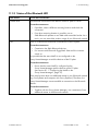
8.1.2 Configuring the NetID on the SMA Radio-controlled Socket
Configuring the NetID for the first time
1. Insert the SMA radio-controlled socket into a socket-outlet.
☑ The upper horizontal LED glows red for approx. 10 seconds, then the vertical LEDs glow
green for approx. 4 seconds.
2. As soon as the LED displays "0", keep tapping the touch key until the LED display shows the
desired NetID.
3. To assume the NetID, wait for 5 seconds. In the process, do not tap the touch key.
Changing the NetID
Requirements:
☐ The SMA radio-controlled socket is inserted in a socket-outlet.
☐ The upper horizontal LED glows orange or green.
1. Hold the touch key down for approx. 2 seconds.
☑ The LED display shows the last configured NetID.
2. Keep tapping the touch key until the desired NetID is displayed.
3. To assume the NetID, wait for 5 seconds. In the process, do not tap the touch key
8.2 Establishing Connection to the Sunny Portal
Requirements:
☐ DHCP is activated on the router (see manual of the router).
☐ The Sunny Home Manager is connected to the router
(see section 7.3 "Connecting the Sunny Home Manager to the Router", page 33).
☐ The Sunny Home Manager is supplied with voltage
(see section 7.4 "Supplying the Sunny Home Manager With Voltage", page 34).
The Sunny Home Manager automatically establishes a connection to the Sunny Portal. As soon as the
status LED intermittently flashes green and orange after approx. 2 minutes, you can register the
Sunny Home Manager in the Sunny Portal (see section 8.3 "Registering in the Sunny
Portal", page 39).
If the status LED continuously flashes red, the Sunny Home Manager cannot automatically establish
the connection to the Sunny Portal. This is the case, for example, if there is a proxy server in your
network or if your router does not support DHCP.
• If the status LED continuously flashes red or you have to manually configure the IP address in
your network, use the Sunny Home Manager Assistant
(see section 9.4 "Using Sunny Home Manager Assistant", page 56).
38
HoMan-IA-IEN121212
Installation Manual
SMA Solar Technology AG
8 Commissioning
8.3 Registering in the Sunny Portal
The Sunny Portal acts as a user interface of the Sunny Home Manager. Therefore, you must register
the Sunny Home Manager in the Sunny Portal.
Requirements:
☐ The status LED of the Sunny Home Manager intermittently flashes green and orange
(see section 8.2 "Establishing Connection to the Sunny Portal", page 38).
☐ The same NetID is configured for all Bluetooth devices.
☐ The Bluetooth PV plant is commissioned.
Procedure:
• Start the Plant Setup Assistant.
• Register as a new user in the Sunny Portal.
or
Log in to the Sunny Portal as an existing user.
• Register the Sunny Home Manager plant in the Sunny Portal.
• Enter the plant password.
• Configure the energy meter.
• Enter the plant data.
Tip: If you have SMA radio-controlled sockets, insert the SMA radio-controlled sockets into the socketoutlets and configure the NetID of the PV plant (see section 8.1.2 "Configuring the NetID on the
SMA Radio-controlled Socket", page 38). As a result, you can register the SMA radio-controlled
socket together with the Sunny Home Manager.
Starting the Plant Setup Assistant
The Plant Setup Assistant is a step-by-step guide of the processes required for user registration and the
registration of Sunny Home Manager plants in the Sunny Portal
1. Open www.SunnyPortal.com and select [Plant setup assistant].
or
Open www.SunnyPortal.com/Register.
☑ The Plant Setup Assistant opens.
2. Select [Next].
☑ The "User registration" page opens.
Installation Manual
HoMan-IA-IEN121212
39
8 Commissioning
SMA Solar Technology AG
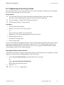
Registering as a new user in Sunny Portal
1. Activate the "I'm new here" field and select [Next].
2. Enter data necessary for registration.
3. Select [Next].
☑ You will receive an e-mail containing a link and your access credentials to Sunny Portal after
a few minutes.
✖ You didn't receive an e-mail from Sunny Portal?
Possibly, the e-mail was automatically redirected to your spam mail folder.
• Check whether the e-mail was redirected to the spam mail folder.
You may have stated a different e-mail address.
• Check whether the e-mail was sent to another e-mail address.
• If the other e-mail address is an unknown address, restart the Plant Setup Assistant and
register as a user again.
4. Follow the link in the confirmation e-mail within 24 hours.
☑ Sunny Portal will confirm in a window that registration was successful.
• Select [Next].
• The "Identify communication product" page opens.
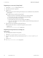
Registering to Sunny Portal as an existing user
Requirements:
☐ You already have one plant in Sunny Portal.
1. Select the "I am already registered in Sunny Portal" field.
2. Enter the e-mail address and Sunny Portal password in the "E-mail Address" and "Password"
fields.
3. Select [Next].
☑ The "Identify communication product" page opens.
40
HoMan-IA-IEN121212
Installation Manual
SMA Solar Technology AG
8 Commissioning
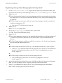
Registering a Sunny Home Manager plant in Sunny Portal
1. On the "Identify communication product" page, enter the previously noted serial number and
registration ID of the Sunny Home Manager in the "Serial Number" and "Registration ID" fields.
2. Select [Identify].
☑ Sunny Portal searches for the Sunny Home Manager with the corresponding serial number
and registration ID. The Plant Setup Assistant shows the correct Sunny Home Manager with
a green tick.
✖ The Plant Setup Assistant cannot find any Sunny Home Managers with the entered serial
number and registration ID?
• See section 9 "Troubleshooting", page 46
3. Select [Next].
☑ The "Select plant" page opens.
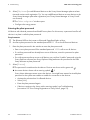
4. Activate the "Create a new plant" field and enter a plant name
(e.g. My Sunny Home Manager plant).
5. Select [Next].
☑ Sunny Home Manager searches for any available Bluetooth devices. After a maximum of
10 minutes the Plant Setup Assistant lists the serial number of any available Bluetooth
devices.
✖ The Plant Setup Assistant is unable to establish a connection to the Sunny Home Manager
and any available Bluetooth devices?
or
✖ The Plant Setup Assistant does not list any or not all Bluetooth devices in your PV plant?
• Select [Refresh]. If the Plant Setup Assistant continues not to list any or not all Bluetooth
devices, see Troubleshooting (see section 9.3 "Error During Registration to Sunny
Portal", page 51).
or
✖ The Plant Setup Assistant lists own but also third-party devices?
• See Troubleshooting (see section 9.3 "Error During Registration to Sunny
Portal", page 51).
6. Activate the selection box of the devices you would like to add to the Sunny Home Manager
plant. Tip: You can identify devices using the previously noted serial number.
7. Select [Add] to add Bluetooth devices to the Sunny Home Manager plant immediately.
☑ A window prompting the plant password opens.
Installation Manual
HoMan-IA-IEN121212
41
8 Commissioning
SMA Solar Technology AG
8. Select [Skip forward] to add Bluetooth devices to the Sunny Home Manager plant at a later
time and continue with registration. Tip: You can add Bluetooth devices as new devices to the
Sunny Home Manager plant after registration (see "Sunny Home Manager in Sunny Portal"
user manual).
☑ The "Meter configuration" window opens.
• Configure the energy meters.
Entering the plant password
All devices with identical password and NetID form a plant. For this reason, a password used for all
devices in a plant is called a plant password.
Requirements:
☐ The Bluetooth LED on the inverter or Bluetooth Piggy-Back lights up blue.
☐ A uniform plant password or the standard password 1111 is set on all Bluetooth devices.
1. Enter the plant password in the window to enter the plant password:
• Enter a new plant password if the standard password 1111 is still set on all devices.
• If a uniform password has already been set on all devices, enter this password as plant
password.
• If a uniform password was not set on all devices, set a uniform "installer" password using the
Sunny Explorer software (see Sunny Explorer Help) and enter this password in the Plant
Setup Assistant as plant password.
2. Select [Connect].
☑ The password is transferred to the devices. Devices are shown with a green tick:
✖ Are some devices shown with a warning symbol:
.
?
Sunny Home Manager cannot access the devices. You might have entered an invalid plant
password or the system was unable to establish a connection to the devices.
• Activate the selection box for affected devices.
• Select [Add].
• Enter the plant password again.
• If devices continue to be shown with a warning symbol, see Troubleshooting
(see section 9.3 "Error During Registration to Sunny Portal", page 51).
42
HoMan-IA-IEN121212
Installation Manual
SMA Solar Technology AG
8 Commissioning
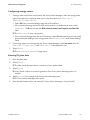
Configuring energy meters
1. If energy meters have been connected to the Sunny Home Manager, select the energy meter
type connected to the respective meter input in the drop-down lists "Meter input 1",
"Meter input 2", "Meter input 3":
• Select D0 if the connected energy meter has a D0 interface.
• If the connected energy meter has a D0 interface and it is a bidirectional meter, select
"Meter input 1" D0 and activate the Bidirectional meter (consumption and feed-in)
field.
☑ The "Meter input 2" area is grayed out.
• If the connected energy meter has an S0 interface, select S0 and enter the previously noted
pulses and meter readings of the energy meter in the "S0 pulses/kWh" and "Meter reading"
fields.
2. If no energy meters are connected to the Sunny Home Manager, select no meter each for
"Meter input 1", "Meter input 2" and "Meter input 3" in the drop-down lists.
3. Select [Next].
☑ The "Extended plant properties" page opens.
Entering PV plant data
1. Enter the plant data.
2. Select [Next].
☑ The Plant Setup Assistant shows a summary of your entered data.
3. Select [Finish].
☑ Sunny Portal confirms successful registration of the Sunny Home Manager plant in a
window.
4. Select [To to plant] to change to the Sunny Home Manager plant.
☑ The Sunny Home Manager plant opens.
5. Enter the plant features (see user manual in "Sunny Home Manager in Sunny Portal“).
Installation Manual
HoMan-IA-IEN121212
43
8 Commissioning
SMA Solar Technology AG
8.4 Configuring the Operating Mode of the SMA Radio-controlled
Socket
Requirements:
☐ The SMA radio-controlled socket is inserted into the socket-outlet.
☐ The upper horizontal LED glows orange or green.
You can configure the operating mode of the SMA radio-controlled socket via the touch key of the
SMA radio-controlled socket or via the Sunny Portal (see user manual "Sunny Home Manager in the
Sunny Portal").
Operating Mode
Explanation
"Automatic"
Control the SMA radio-controlled socket using the
Sunny Home Manager. Depending on the current control command
of the Sunny Home Manager, the SMA radio-controlled socket is
either switched on or switched off in this mode.
• Switched on: The connected load can draw power.
• Switched off: The connected load cannot draw any power.
"Manually switched on"
The SMA radio-controlled socket is switched on.
The connected load can draw power.
The SMA radio-controlled socket is not controlled by the
Sunny Home Manager.
"Manually switched off"
The SMA radio-controlled socket is switched off.
The connected load cannot draw any power.
The SMA radio-controlled socket is not controlled by the
Sunny Home Manager.
44
HoMan-IA-IEN121212
Installation Manual
SMA Solar Technology AG
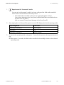
1.
8 Commissioning
Requirement for "Automatic" mode
You can only set "Automatic" mode if you have configured the SMA radio-controlled
socket for the connected load in the Sunny Portal.
• If the SMA radio-controlled socket was not registered together with the
Sunny Home Manager in the Sunny Portal, add the SMA radio-controlled socket to
the plant as a new device
(see user manual "Sunny Home Manager in the Sunny Portal").
2. Keep tapping the touch key until the upper horizontal LED displays the desired operating mode:
Operating Mode
LED Status
"Manually switched on"
Glows green
"Automatic"
Off
"Manually switched off"
Glows orange
3. To assume the operating mode, wait approx. 1 second. In the process, do not press the touch
key.
☑ After approx. 2 seconds, the SMA radio-controlled socket audibly switches to the selected
operating mode.
Installation Manual
HoMan-IA-IEN121212
45
9 Troubleshooting
9
SMA Solar Technology AG
Troubleshooting
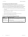
9.1 Error in the Sunny Home Manager
9.1.1 States of all LEDs
LED Status
Cause and Correction
Off
The Sunny Home Manager is not supplied with voltage.
Corrective measures:
• Supply the Sunny Home Manager with voltage (see section 7.4).
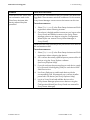
9.1.2 States of the Status LED
LED Status
Cause and Correction
Glows red
The system starts.
Corrective measures:
• Do not disconnect the Sunny Home Manager from the voltage
supply.
If the status persists: Error.
Corrective measures:
• Disconnect the Sunny Home Manager from the voltage supply and
then supply it with voltage once again (see section 7.4).
• If the status continues to persist, contact the SMA Service Line.
Flashes red
The Sunny Home Manager cannot establish a connection to the
Sunny Portal. It is possible that there is a proxy server in your network or
DHCP is not activated in your router.
Corrective measures:
• Use the Sunny Home Manager Assistant (see section 9.4).
The Sunny Home Manager cannot establish a connection to the
Sunny Portal. It is possible that the Sunny Home Manager is not correctly
connected to the router.
Corrective measures:
• Ensure that the Sunny Home Manager is correctly connected to the
router (see section 7.3).
• If the Sunny Home Manager is correctly connected to the router and
the status LED continues to flash red, completely reset the
Sunny Home Manager (see section 9.6).
46
HoMan-IA-IEN121212
Installation Manual
SMA Solar Technology AG
9 Troubleshooting
LED Status
Cause and Correction
Flashing green and
orange intermittently
The Sunny Home Manager is connected to the Sunny Portal, but is not yet
registered in the Sunny Portal.
Corrective measures:
Register the Sunny Home Manager in the Sunny Portal (see section 8.3).
Flashes green
The Sunny Home Manager is connected to the devices of the PV plant and
the Sunny Portal. There is an "Error" type event present in at least one
device or at least one device is not connected to the
Sunny Home Manager.
Corrective measures:
• Call up the error in the plant log book of the Sunny Portal
(see user manual "Sunny Home Manager in the Sunny Portal").
• Read the meaning of the error in the manual of the affected device.
Glows orange
The Sunny Home Manager has not been connected to the Sunny Portal for
at least 10 minutes.
There are no new events in the cache of the Sunny Home Manager.
Corrective measures:
• If the status persists, check the connection status with the
Sunny Home Manager Assistant (see section 9.4 "Using Sunny
Home Manager Assistant", page 56).
Installation Manual
HoMan-IA-IEN121212
47
9 Troubleshooting
SMA Solar Technology AG
LED Status
Cause and Correction
Flashing red and
orange intermittently
The Sunny Home Manager has not been connected to the Sunny Portal for
at least 10 minutes.
There is an "Error" type event present in at least one device or at least one
device is not connected to the Sunny Home Manager.
The event and the data read out cannot be sent to the Sunny Portal.
The event and the data are cached in the Sunny Home Manager.
Corrective measures:
• Ensure that the Sunny Home Manager is correctly connected to the
router (see section 7.3).
• Check whether the internet connection is functioning:
• In the browser window, enter e.g. www.SMA.de/en and
confirm with the [Enter] key.
• If the internet connection is continuously impaired, ensure that the
router is functioning correctly. If necessary, contact the internet
service provider and read out the device errors present on the
inverter display (see manual of the inverter).
• When the Sunny Home Manager is reconnected to the Sunny Portal,
call up the event in the plant log book of the Sunny Portal (see the
user manual of the Sunny Portal for Sunny Home Manager).
48
HoMan-IA-IEN121212
Installation Manual
SMA Solar Technology AG
9 Troubleshooting
9.1.3 States of the Bluetooth LED
LED Status
Cause and Correction
Flashes blue
The Bluetooth connection to the devices of the PV plant is critical.
Corrective measures:
• If possible, select a different mounting location and check the
connection.
• If no other mounting location is possible, use an
SMA Bluetooth repeater or an SMA radio-controlled socket. As a
result, you can extend the wireless range of your Bluetooth network.
Off
There is no Bluetooth connection to the devices of the PV plant.
Corrective measures:
• Commission the SMA Bluetooth devices.
• For inverters with Bluetooth Piggy-Back: Wait until the inverters
switch on.
It is possible that the same NetID is not configured on the
Sunny Home Manager as with the devices of the PV plant.
Corrective measures:
• Ensure that the same NetID is configured on the
Sunny Home Manager and the devices of the PV plant
(see section 8.1.1 "Configuring the NetID on the
Sunny Home Manager", page 37).
There may be more than one additional master in your Bluetooth network
(e.g. Sunny Beam and computer with Sunny Explorer). Therefore, the
Sunny Home Manager cannot establish a connection to the Bluetooth
devices.
Corrective measures:
• Together with the Sunny Home Manager, use a maximum of one
additional master in the Bluetooth network.
Installation Manual
HoMan-IA-IEN121212
49
9 Troubleshooting
SMA Solar Technology AG
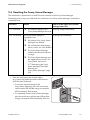
9.2 Error in the SMA Radio-controlled Socket
States of the lower horizontal LED
LED Status
Cause and Correction
Flashes blue
The Bluetooth connection to the Sunny Home Manager is critical.
Corrective measures:
• If possible, select a different mounting location.
• If no other mounting location is possible, use an
SMA Bluetooth Repeater or an additional SMA radio-controlled
socket. As a result, you can extend the wireless range of your
Bluetooth network.
Off
There is no Bluetooth connection between the SMA radio-controlled
socket and the Sunny Home Manager.
Corrective measures:
• Ensure that the Sunny Home Manager is supplied with voltage
(see section 7.4).
• Ensure that the same NetID is configured on the
SMA radio-controlled socket and the Sunny Home Manager
(see section 8.1.2 "Configuring the NetID on the SMA Radiocontrolled Socket", page 38).
• If possible, select a different mounting location.
• If no other mounting location is possible, use an
SMA Bluetooth Repeater or an additional SMA radio-controlled
socket. As a result, you can extend the wireless range of your
Bluetooth network.
50
HoMan-IA-IEN121212
Installation Manual
SMA Solar Technology AG
9 Troubleshooting
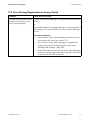
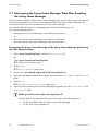
9.3 Error During Registration to Sunny Portal
Problem
Cause and Correction
The Plant Setup Assistant cannot Possibly Sunny Home Manager is not correctly connected to the
establish a connection to the
router.
Sunny Home Manager.
or
It is possible that the Sunny Home Manager is not being supplied
with voltage. In this case, all LEDs of the Sunny Home Manager
are off.
Corrective measures:
• Ensure that the Sunny Home Manager has been correctly
connected to the router (see section 7.3).
• Ensure that the Sunny Home Manager is supplied with
voltage (see section7.4 "Supplying the Sunny Home
Manager With Voltage", page 34).
• Contact the SMA Service Line if the Sunny Home Manager
has been correctly connected to the router and is connected
to the mains but all LEDs remain off.
Installation Manual
HoMan-IA-IEN121212
51
9 Troubleshooting
SMA Solar Technology AG
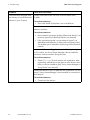
Problem
Cause and Correction
The Plant Setup Assistant does
not list any or not all Bluetooth
devices in your PV plant.
Possibly some devices are set to an incorrect NetID of the
PV plant.
Corrective measures:
• Ensure the NetID of the plant is set on all devices.
The wireless connection of several devices may be disturbed by
ambient conditions.
Corrective measures:
• Ensure that the connection quality of Bluetooth devices is at
minimum "good" (see Bluetooth device user manual).
• If the connection quality is not at minimum "good", use
SMA Bluetooth Repeater or SMA radio-controlled socket.
This enables you to extend the radio range of the Bluetooth
network.
Inverters with Bluetooth Piggy-Back switch off during the night.
For this reason, the Sunny Home Manager cannot establish a
connection to these inverters during this time.
Corrective measures:
• Select [Skip forward] and continue with registration. After
registration, add devices to the plant as new devices when
there is sufficient irradiation (see "Sunny Home Manager in
Sunny Portal" user manual).
Possibly the devices in your PV plant are not in operation. For this
reason, Sunny Home Manager cannot establish a connection to
these devices.
Corrective measures:
• Commission the devices.
52
HoMan-IA-IEN121212
Installation Manual
SMA Solar Technology AG
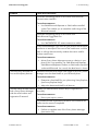
Problem
9 Troubleshooting
Cause and Correction
Insufficient transmitting power of the inverter with Bluetooth
communication interface.
Corrective measures:
• Use SMA Bluetooth Repeater or SMA radio-controlled
socket. This enables you to extend the radio range of the
Bluetooth network.
Insufficient transmitting power of the inverter with
SMA Bluetooth Piggy-Back Plus.
Corrective measures:
• Use "ANTEXTKIT25-10" antenna extension add-on.
Sunny Home Manager is too far from your plant or the Bluetooth
connection is interrupted. The cause of the interference could be
walls or ceilings that excessively weaken the waves used for
wireless transmission.
Corrective measures:
• Mount Sunny Home Manager nearer to a device in your
plant. If this is not possible, use SMA Bluetooth Repeater,
SMA Bluetooth Repeater Outdoor or SMA radio-controlled
socket with Bluetooth. As a result, the dead zone is closed.
The Plant Setup Assistant lists
own and third-party devices.
A different Bluetooth plant within radio range of the Sunny Home
Manager uses the same NetID as your Bluetooth plant.
Corrective measures:
• Determine a free NetID for your plant using Sunny Explorer
(see Sunny Explorer Help).
• Adjust the determined NetID in all devices.
The Plant Setup Assistant cannot Possibly you entered serial number and/or registration ID
find a Sunny Home Manager incorrectly.
with the serial number and
Corrective measures:
registration ID entered.
• Ensure your input is correct.
It is possible that the registration procedure was initiated at an
earlier time but was not completed.
Corrective measures:
• Perform a complete reset of the Sunny Home Manager
(see section 9.6).
Installation Manual
HoMan-IA-IEN121212
53
9 Troubleshooting
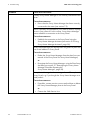
Problem
SMA Solar Technology AG
Cause and Correction
Possibly Sunny Home Manager is not correctly connected to the
router.
Corrective measures:
• Ensure that the Sunny Home Manager has been correctly
connected to the router (see section 7.3).
DHCP is possibly not activated on your router or there is a proxy
server in your network. For this reason, Sunny Home Manager
cannot establish a connection to the Sunny Portal.
Corrective measures:
• Establish the connection to the Sunny Portal using the
Sunny Home Manager Assistant (see section 9.4 "Using
Sunny Home Manager Assistant", page 56).
Sunny Home Manager has already been assigned to a plant with
your e-mail address in Sunny Portal.
Corrective measures:
• Delete the Sunny Home Manager from the plant (see user
manual of the Sunny Portal for Sunny Home Manager).
or
• Re-register the Sunny Home Manager using the Plant Setup
Assistant (see section 9.7 "Reassigning the Sunny Home
Manager Plant After Resetting the
Sunny Home Manager", page 58).
Sunny Home Manager has been assigned to a different plant in
Sunny Portal, e.g. if you bought the Sunny Home Manager as a
used product.
Corrective measures:
• If possible, contact previous owners and ask them to delete
the Sunny Home Manager plant in the Sunny Portal.
or
• Contact the SMA Service Line.
54
HoMan-IA-IEN121212
Installation Manual
SMA Solar Technology AG
9 Troubleshooting
Problem
Cause and Correction
Some devices are shown with
an exclamation mark in the
Plant Setup Assistant after
having entered the plant
password.
The devices with exclamation marks are inverters with Bluetooth
Piggy-Back. These inverters switch off in darkness. For this reason,
Sunny Home Manager cannot access the inverters at this time.
Corrective measures:
1. Select [Skip forward] in the Plant Setup Assistant and finish
registration without selecting inverters.
2. Once there is daylight and the inverters are on, log on to the
Sunny Portal and add the inverters to the Sunny Home
Manager plant as new devices using the Configuration
Wizard (see user manual "Sunny Home Manager in
Sunny Portal").
A different electrically qualified person password is set on devices
with exclamation marks.
Corrective measures:
1. Select [Skip forward] in the Plant Setup Assistant and finish
registration without selecting the devices
2. Set a uniform electrically qualified person password for all
devices using the Sunny Explorer software
(see Sunny Explorer Help).
3. If you do not know the password set on each device, apply
for a Personal Unlocking Key (PUK) for each device from
SMA Service Line.
4. Use Sunny Explorer to enable each device with the
corresponding PUK. Subsequently set a uniform installer
password in all devices (see Sunny Explorer Help).
5. Log in to Sunny Portal and add the devices to the
Sunny Home Manager plant as new devices using the
Configuration Wizard (see Sunny Portal user manual for
Sunny Home Manager).
Installation Manual
HoMan-IA-IEN121212
55
9 Troubleshooting
SMA Solar Technology AG
9.4 Using Sunny Home Manager Assistant
The Sunny Home Manager Assistant helps you to configure the Sunny Home Manager for your
network if the Sunny Home Manager does not automatically connect with the Sunny Portal.
In addition, you can use the Sunny Home Manager Assistant to display the latest connection status to
the Sunny Portal, the network settings and the connected Bluetooth devices, and save as a log file. In
the event of a service, the SMA Service Line can evaluate this log file and read out problems.
1. Using a network cable, connect the computer to the router to which the Sunny Home Manager
is connected.
2. In the download area on www.SMA.de/en, download the Sunny Home Manager Assistant for
the operating system of your computer.
or
Insert the provided CD into the drive of your computer.
3. Start the Sunny Home Manager Assistant by double-clicking on the file name.
4. Follow the Sunny Home Manager Assistant instructions.
9.5 Error in the Sunny Home Manager Assistant
Problem
Cause and Correction
The Sunny Home
The computer with the Sunny Home Manager Assistant is not connected
Manager Assistant
to the router to which the Sunny Home Manager is connected.
does not detect a
Corrective measures:
Sunny Home Manager
• Connect the computer with the Sunny Home Manager Assistant to
the router to which the Sunny Home Manager is connected.
56
HoMan-IA-IEN121212
Installation Manual
SMA Solar Technology AG
9 Troubleshooting
9.6 Resetting the Sunny Home Manager
The reset button is positioned in a small hole on the bottom of the Sunny Home Manager.
Depending on how long you hold down the reset button, the Sunny Home Manager is partially or
completely reset.
Duration
1 to 5 seconds
5 to 10 seconds
Result
Status of the status LED and the
energy meter LED
☑ The network settings of the
Flashing orange intermittently
Sunny Home Manager are reset.
The Sunny Home Manger is
completely reset:
Flashing red intermittently
☑ All settings of the Sunny Home
Manager are deleted.
☑ All cached plant data (energy
values, events, etc.) are deleted.
☑ The Sunny Home Manager
redetects the Bluetooth devices
in range.
☑ The Sunny Home Manager must
be registered once more in the
Sunny Portal (see section
9.7 "Reassigning the Sunny
Home Manager Plant After
Resetting the
Sunny Home Manager", page 58).
• Press the reset button with a sharp object
(e.g. paper clip) and hold until the desired reset
result has been achieved:
• To reset the network settings of the
Sunny Home Manager, press the reset button
until the status LED and the energy consumption
LED intermittently flash orange.
• To completely reset the Sunny Home Manager,
press the reset button until the status LED and the
energy consumption LED intermittently flash red.
Installation Manual
HoMan-IA-IEN121212
57
9 Troubleshooting
SMA Solar Technology AG
9.7 Reassigning the Sunny Home Manager Plant After Resetting
the Sunny Home Manager
Once you have completely reset the Sunny Home Manager (see section 9.6), you must reassign the
Sunny Home Manager to your Sunny Home Manager plant in the Sunny Portal. Otherwise, the
Sunny Portal will not assume any data from the Sunny Home Manager.
You have the following options for reassigning the Sunny Home Manager to your
Sunny Home Manager plant:
• Reassign the Sunny Home Manager via the Plant Setup Assistant.
or
• Reassign the Sunny Home Manager via the Sunny Portal access
(see user manual "Sunny Home Manager in the Sunny Portal").
Reassigning the Sunny Home Manager of the Sunny Home Manager plant using
the Plant Setup Assistant
1. Open www.SunnyPortal.com and select [Plant setup assistant].
or
Open www.SunnyPortal.com/Register.
☑ The Plant Setup Assistant opens.
2. Select [Next].
☑ The "User registration" page opens.
3. Activate the I am already registered in the Sunny Portal field.
4. Enter the e-mail address and the Sunny Portal password in the "E-mail Address" and "Password"
fields.
5. Select [Next].
☑ The "Identify communication product" page opens.
6. Enter the serial number and Sunny Home Manager registration ID in the "Serial Number" and
"Registration ID" fields.
Reading out the serial number and registration ID
You can read out the registration ID and serial number in the following areas:
• On the type label on the rear of the Sunny Home Manager
• On the cover of the supplied CD
58
HoMan-IA-IEN121212
Installation Manual
SMA Solar Technology AG
9 Troubleshooting
7. Select [Identify].
☑ Sunny Portal checks whether the entered serial number and registration ID corresponds to
the connected Sunny Home Manager.
✖ The Plant Setup Assistant cannot find a Sunny Home Manager with the stated serial number
and registration ID?
• See Troubleshooting (see section 9 "Troubleshooting", page 46).
8. Select [Next].
☑ The Plant Setup Assistant lists all Sunny Home Manager plants.
9. Activate the field of the Sunny Home Manager plant to which you wish to assign the
Sunny Home Manager.
10. Select [Next].
☑ The "Device replacement summary" page opens.
11. Select [Finish].
9.8 Resetting the SMA Radio-controlled Socket to Default Settings
You must reset the SMA radio-controlled socket to default settings in the following cases:
• You wish to operate the SMA radio-controlled socket in a different plant.
• You wish to reset the measured values of the SMA radio-controlled socket.
1. Unplug the SMA radio-controlled socket from the socket-outlet and re-insert it into the socketoutlet.
☑ The upper horizontal LED glows red for approx. 10 seconds.
2. As soon as the horizontal LEDs glow green, press and hold the touch key for 5 seconds. For this
purpose, do not release the key until the upper horizontal LED glows red.
☑ The NetID is reset to "0".
☑ The measured values are reset.
☑ The plant password is reset to the default password 1111.
Installation Manual
HoMan-IA-IEN121212
59
10 Decommissioning
SMA Solar Technology AG
10 Decommissioning
10.1 Disassembling the Sunny Home Manager
1. If the Sunny Home Manager is supplied with voltage via the plug-in power supply:
• Unplug the plug-in power supply from the socket-outlet.
• Unplug the DC plug of the plug-in power supply from the terminal "Power".
2. If the Sunny Home Manager is supplied with voltage via a top-hat rail power supply:
Risk of lethal electric shock
Lethal voltages are present at the connection location of the power distribution grid.
• Disconnect the connection location from the power distribution grid using the separator
(e.g. distribution board).
• Unplug the connection plug of the top-hat rail power supply on the Sunny Home Manager
from the connection socket.
3. Unplug the connection plugs of the energy meters from the connection sockets.
4. Unplug the network cable from the Ethernet terminal of the Sunny Home Manager.
5. Unplug the other end of the network cable from the router.
6. If the Sunny Home Manager is mounted on the
wall, push the Sunny Home Manager upward and
remove it from the wall.
60
HoMan-IA-IEN121212
Installation Manual
SMA Solar Technology AG
10 Decommissioning
7. If the Sunny Home Manager is mounted on a top-hat rail, remove the Sunny Home Manager
from the top-hat rail:
• Push the Sunny Home Manager downward. In
the process, pivot the Sunny Home Manager
with the lower edge facing forward and remove
from the top-hat rail.
10.2 Packing the Sunny Home Manager/SMA Radio-controlled
Socket for Dispatch
• Pack the device. For this purpose, use the original packaging or packaging suitable for the
weight and dimension of the device (see section 11 "Technical Data", page 62).
10.3 Disposal of the Sunny Home Manager/SMA Radio-controlled
Socket
• Dispose of the device according to the disposal regulations for electronic waste that apply at
the installation site.
or
• Send the device to SMA Solar Technology AG at your own expense (see
section 14 "Contact", page 69). When doing so, label the packaging "ZUR ENTSORGUNG"
("FOR DISPOSAL").
Installation Manual
HoMan-IA-IEN121212
61
11 Technical Data
SMA Solar Technology AG
11 Technical Data
11.1 Sunny Home Manager
General data
Status display
LEDs
Maximum length of the cable to energy meters
with S0 interface
30 m
Maximum length of the cable to energy meters
with D0 interface
15 m
Certified countries
Australia, Belgium, Germany, France, Italy,
Greece, Great Britain, Canada, Luxembourg,
Portugal, Spain, Czech Republic, Austria,
Switzerland, USA
Mechanical data
Width x height x depth
Weight
170 mm x 124.5 mm x 41.5 mm
220 g
Voltage supply
Voltage supply
Plug-in power supply, top-hat rail power supply
DC input voltage
12 V
Maximum typical power consumption
6W
Maximum power consumption
14.3 W
Terminals
RJ45
Ethernet*
Number of 2x4-pole Combicon jacks for energy
meters
3
Number of USB jacks**
2
* Data rate 10 Mbit per second or 100 Mbit per second
** Currently without function.
62
HoMan-IA-IEN121212
Installation Manual
SMA Solar Technology AG
11 Technical Data
Ambient conditions in operation
Ambient temperature*
Relative humidity**
Degree of protection***
Maximum height above MSL
− 25 °C … +60 °C
5 % … 95 %
IP20
2 000 m
* Sunny Home Manager at temperatures below 0°C or exceeding 40 °C, do not use the plug-in power supply included in
the delivery (see Section 11.3 "Plug-in Power Supplies", page 65). Requirements of the plug-in power supply: 12 V DC,
nominal current: 1.5 A.
** Non-condensing
*** according to IEC 60529
Communication interface to other devices
SMA devices
Bluetooth
Computer
Ethernet
Sunny Portal
Ethernet
Maximum communication range
Bluetooth*
100 m
Ethernet
100 m
* Maximum free-field communication range
Memory
Internal memory
32 MB
Number of devices
Maximum total number of SMA devices
16
Maximum number of SMA inverters
12
Maximum number of SMA radio-controlled
sockets
10
Installation Manual
HoMan-IA-IEN121212
63
11 Technical Data
SMA Solar Technology AG
11.2 SMA Radio-controlled Socket
General data
Status display
Certified countries
LEDs
Belgium, Germany, France, Greece, Great
Britain, Italy, Canada, Luxembourg, Austria,
Portugal, Spain, Czech Republic, USA,
Switzerland
Mechanical data
Width x height x depth
Weight
118 mm x 76 mm x 56 mm
156 g
Voltage supply
Voltage
100 V … 240 V
Frequency
50/60 Hz
Maximum current
16 A
Minimum power consumption
0.25 W
Maximum power consumption
1.5 W
Maximum switching power with resistive load
Maximum switching power with lamp load
Maximum switching power with inductive load
with a displacement power factor of
cos φ > 0.65
3 680 W
600 W
1 200 VA
Ambient conditions in operation
Ambient temperature
Relative humidity*
− 5°C … +65°C
5% … 95%
Degree of protection (IP)**
IP20
Maximum height above MSL
3 000 m
* Non-condensing
** According to IEC 60529
64
HoMan-IA-IEN121212
Installation Manual
SMA Solar Technology AG
11 Technical Data
Ambient conditions during transport/storage
Ambient temperature
− 25°C … +80°C
5% … 95%
Relative humidity*
Maximum height above MSL
3 000 m
* Non-condensing
Communication interface to other devices
Bluetooth
Sunny Home Manager
Maximum communication range
Bluetooth*
100 m
* Maximum free-field communication range
11.3 Plug-in Power Supplies
11.3.1 TaiyTech, TYT251200200UV/3000M
Mechanical data
Width x height x depth
Weight
92.0 mm x 58.0 mm x 41.4 mm
244 g
Voltage supply
Voltage
Frequency
Maximum current
100 V AC … 240 V AC
50/60 Hz
0.85 A
Ambient conditions in operation
Ambient temperature
Installation Manual
0°C … + 45°C
HoMan-IA-IEN121212
65
11 Technical Data
SMA Solar Technology AG
11.3.2 TaiyTech, TYT251200200EU/3000M
Mechanical data
Width x height x depth
Weight
92.0 mm x 90.6 mm x 36.0 mm
190 g
Voltage supply
Voltage
100 V AC … 240 V AC
Frequency
50/60 Hz
Maximum current
0.85 A
Ambient conditions in operation
Ambient temperature
0°C … + 45°C
11.3.3 CINCON, TRG30R 120
Mechanical dimensions
Width x height x depth
Weight
107.8 mm x 57.5 mm x 33.5 mm
300 g
Voltage supply
Voltage
100 V … 240 V AC
Frequency
50 / 60 Hz
Maximum current
0.8 A
Ambient conditions in operation
Ambient temperature
66
HoMan-IA-IEN121212
0°C … + 40°C
Installation Manual
SMA Solar Technology AG
12 Accessories
12 Accessories
Designation
Brief description
Reading head
Cable with optical reading
HM-D0-METERADAPTER
head and 4-pole plug for
energy meters with D0 interface
SMA radio-controlled socket
SMA Radio-controlled socket
with Bluetooth Wireless
Technology
Installation Manual
SMA order number
BT-SOCKET-10
HoMan-IA-IEN121212
67
13 Software Licenses
SMA Solar Technology AG
13 Software Licenses
The licenses for the software modules used can be found on the CD provided.
68
HoMan-IA-IEN121212
Installation Manual
SMA Solar Technology AG
14 Contact
14 Contact
If you have technical problems concerning our products, contact the SMA Service Line. We need the
following data in order to provide you with the necessary assistance:
• Serial number and firmware version of the Sunny Home Manager
• Serial number and firmware version of the SMA radio-controlled socket
• Name of the Sunny Home Manager plant
• Energy meter type
• Reading head type
SMA Solar Technology AG
Sonnenallee 1
34266 Niestetal, Germany
www.SMA.de
SMA Service Line
Inverters
+49 561 9522 1499
Communication: +49 561 9522 2499
Fax:
+49 561 9522 4699
E‑Mail:
[email protected]
Installation Manual
HoMan-IA-IEN121212
69
Legal Restrictions
SMA Solar Technology AG
The information contained in these documents is property of SMA Solar Technology AG. Any publication, whether in whole or in
part, requires prior written approval by SMA Solar Technology AG. Internal reproduction used solely for the purpose of product
evaluation or other proper use is allowed and does not require prior approval.
Declaration of Conformity
SMA Solar Technology AG hereby declares that this equipment is in compliance with the essential requirements and other relevant
provisions of Directive 1999/5/EC. You can find the entire CE declaration of conformity at www.SMA.de.
Trademark
All trademarks are recognized, even if not explicitly identified as such. A lack of identification does not mean that a product or
symbol is not trademarked.
The Bluetooth® word mark and logos are registered trademarks owned by Bluetooth SIG, Inc. and any use of these marks by
SMA Solar Technology AG is under license.
SMA Solar Technology AG
Sonnenallee 1
34266 Niestetal
Germany
Tel. +49 561 9522-0
Fax +49 561 9522-100
www.SMA.de
E-mail: [email protected]
© 2004 to 2012 SMA Solar Technology AG. All rights reserved.
70
HoMan-IA-IEN121212
Installation Manual
4."4PMBS5FDIOPMPHZ
XXX4."4PMBSDPN
4."4PMBS5FDIOPMPHZ"(
XXX4."EF
4.""NFSJDB--$
XXX4.""NFSJDBDPN
4."5FDIOPMPHZ"VTUSBMJB1UZ-UE
XXX4.""VTUSBMJBDPNBV
4."#FOFMVY413XXX4."#FOFMVYDPN
4."#FJKJOH$PNNFSDJBM$P-UE
XXX4."$IJOBDPN
4."$[FDI3FQVCMJDTSP
XXX4."$[FDIDPN
4."'SBODF4"4
XXX4."'SBODFDPN
4.")FMMBT"&
XXX4.")FMMBTDPN
4."*C©SJDB5FDOPMPHB4PMBS4-
XXX4."*CFSJDBDPN
4."*UBMJB4SM
XXX4."*UBMJBDPN
4."5FDIOPMPHZ,PSFB$P-UE
XXX4.",PSFBDPN