1
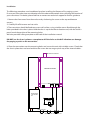
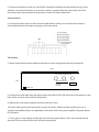
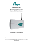
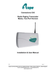
Response Plus
Paging System
INSTALLATION
MANUAL
All information contained within this document is
confidential and belongs solely to Honeywell PLC
and its subsidiaries and is copyright protected. ©
RESPONSE PLUS SYSTEM
Introduction
The Response Plus Paging System is a POCSAG data display radio paging system, which can be used
to transmit both text and numeric messages direct to alphanumeric pagers with closed contact
alarms and direct serial data input. This transmitter can be linked to any alarm systems with clean
contact outputs and specified data protocols covering small to large sized properties.
Product Overview
The Response Plus paging unit consists of a wall-mounted Honeywell branded HIPS (High Impact
Polystyrene) enclosure containing a 2 watt transmitter enclosed in an aluminium surround.
The Response Plus paging unit includes a 240-volt 3-pin plug, status indicator LED for Power and
Transmission, and straight wire antenna, connected to the top of the enclosure using a 3/8 BNC
bayonet connection.
This unit supports four dry volt free contacts and serial data input. The contacts can
be set to normally open N/O or normally closed N/C as required. When activated
these will send pre-programmed messages to a particular pager address (which
could be to an individual pager or group of pagers at the same time), these messages
are pre-programmed and can only be changed by a qualified engineer.
The Response Pro paging unit’s four contact closure inputs are located on an internal terminal header
block, accessible via glands on the base of the unit.
This serial data input is for specified protocols within the paging transmitter. (Please consult the
programming software or help desk for clarification.)
When the alarm panel is activated, these addressable messages will send to a pager or group of
pagers.
The serial data programming software can only be used by a qualified engineer.
The Response Plus paging unit’s serial data input is located at the base of the unit and is connected
via a RS232 9-pin DB serial input connector.
The system requires alphanumeric pagers to receive the alarm messages.
Important Safety Information
This equipment must only be installed and maintained by a suitably skilled and competent person.
This equipment is defined as Class 1 in EN60065 (Low Voltage Directive) and must be EARTHED.
CAUTION INDOOR USE ONLY
WARNING SHOCK HAZARD- ISOLATE BEFORE OPENING
WARNING TO REDUCE THE RISK OF FIRE OR ELECTRIC SHOCK,
DO NOT EXPOSE THIS UNIT IN RAIN OR MOISTURE
WARNING THIS UNIT MUST BE EARTHED
WARNING NO USER SERVICABLE PARTS
Anti-Static Handling Guidelines
Make sure that electro-static handling precautions are taken immediately before handling PCBs and
other static sensitive components.
Before handling any static-sensitive items, operators should get rid of any electrostatic charge
by touching a sound safety earth, such as a radiator. Always handle PCBs by their sides and avoid
touching any components. PCBs should be stored in a clean, dry place that is free from vibration, dust
and excessive heat.
Storing the PCBs in a suitable cardboard box will also guard them against mechanical damage.
Unpacking the Unit
Remove the Response Plus paging unit from its packaging, and check the contents against the
following:
1. Response Plus paging unit, complete with power cable and four enclosure screws
2. Installation and maintenance manual (this document)
3. Straight wire antenna
4. Alphanumeric pagers (quantity as per your order)
Preparation
The information contained in this section is intended for use by authorised system installation
engineers only. Unqualified personnel should not undertake installation of this equipment under any
circumstances.
Locating the equipment
Before locating the hardware in any given location, it is important to take into account the range of
the operation that is required. The transmitter can quite easily provide range of up to a mile or more
(line of site) and will provide full coverage in most medium and large sites. This can be achieved by
fitting our standard antenna connected directly to the unit.
Important: Coaxial feed greater than 5 metres must employ low loss 50 ohm coax. We normally do
not recommend feeds of more than 15 metres for standard applications.
However, we suggest you contact our technical department for guidance and support on the site
survey range test.
Location to Alarm Panel for Serial Input
Direct RS232 serial data between the fire panel and the transmitter unit should be no greater than
15 metres in length of data cable. These cables should be screen/shielded and must be kept clear
of sources of induced magnetic and electrical noise. In the event that distances are over 15 metres,
additional drivers and amplifiers must be installed at both ends of the data link.
Important Installation Notes
• Never install antennas near or adjacent to telephone, public address or data communication
lines or overhead cables.
• Avoid, where possible, running antenna coax alongside other cables.
• Avoid mounting the transmitter in the immediate vicinity of telephone exchanges or
computer equipment.
• Always use proprietary 50 ohm coaxial cable between antenna and the transmitter. If the cable
runs exceed 5 metres, always use low loss 50 ohm cable such as RG213, UR67 or equivalent.
Coax cable intended for TV, Satellite or CCTV installation is normally 75 ohm and therefore
unsuitable for any transmitter installation.
• Also remember that the performance of the system will be affected by the type of material the
unit is mounted in close proximity to.
• The following list of materials that a transmitter will be adversely affected by if mounted on or
if mounted in the close proximity of: foil back plasterboard, metal mesh, wire reinforced glass,
metal sheeting, large mirrors or suspended ceilings and lift shafts.
• NEVER transmit without an aerial attached to the transmitter.
• ALWAYS carefully check the installation section in the manual covering data pin connections
prior to installation. Damage caused by the incorrect connection is the responsibility of the
installer!
Installation
The following procedure must be adhered to when installing the Response Plus paging system.
Ensure you have taken into consideration all of the above information when selecting the location of
your transmitter. If in doubt, please feel free to contact our technical support for further guidance.
1. Remove the front cover from the enclosure by slackening the screws at the top and bottom
corners.
2. Carefully lift off the cover and set aside.
3. The transmitter should be fixed to an even wall surface, using suitable screws fitted through the
holes provided in the chassis plate. Hold the chassis up to the chosen location and, with the aid of a
pencil, mark the position of the mounting holes.
We have provided a fixing template at the back of the installation manual.
DO NOT use the chassis plate as a template to drill the holes as the drill vibration can damage
the paging crystals on the transmitter.
4. Place the transmitter over the mounting holes and secure the unit with suitable screws. Check that
the chassis plate does not bend and that the screws do not snag or pinch any of the internal cables.
%1& $QWHQQD FRQQHFWLRQ
: 8+) 7UDQVPLWWHU
6
5-
6
5-
3RZHU 6XSSO\
9GF
$
ZD\ GU\ FRQWDFW WHUPLQDOV
'U\ &RQWDFW
,QWHUIDFH
5-
PP NQRFN RXW
&20 PP NQRFN RXW PP NQRFN RXW
5. Connect the antenna to the unit via the BNC connector located at the top of the housing. If the
antenna is an external antenna, or an antenna which is separate from the transmitter unit itself,
ensure that the criteria covered in the previous section has been adhered to.
Contact Alarms
6. Connect the alarm inputs to the terminal header block, making sure that the correct input is
connected to the correct output message on the transmitter.
Serial Alarm
7. Please check the RS232 data cable connection has been configured correctly to the panel.
PP
'U\ FRQWDFWV LQ PP .QRFN RXW
PP
6HULDO 'DWD 56 &RP 3LQ 5;'
3LQ 7;'
3LQ *1'
&RP
$& 0DLQV ,QSXW
8. Connect the serial cable from the alarm panel to the RS232 9 Pin DB Serial input connection on the
base of the unit and secure with the fixing bolts.
9. Replace the cover and re-tighten the four enclosure screws.
10. Finally, after checking all connection, connect the mains cable at the base of the unit in to a
suitable switched/fused spur (as applicable) wall outlet. With mains power applied, the green power
LED will be lit.
11. The system is now ready to accept calls from the host panel. When a call is transmitted, the red
transmit LED on the front of the unit will light momentarily.
Radio Transmission Baud Rate
This is set at the factory to suit the pagers supplied and will normally be set at either 512 or 1200
baud. Please refer to the separate configuration sheet and/or delivery note supplied with the unit.
Operation
To test the system, please activate each alarm panel that has been connected to the Response Plus
paging system,
1 - to ensure that the contact interface sends the correct message to the alphanumeric pagers.
2 – the serial interface is sending the addressable messages to the alphanumeric pagers.
Indications
Each time the alarm is activated, the TRANSMIT light will momentarily illuminate to confirm that the
message has been sent to the pager.
No TRANSMIT light:
• check power to the unit
• check contact interface connections
• check alphanumeric pager is switched on and has full battery power
• possible transmitter fault
Please note that the green POWER light should flicker constantly to signify that the unit is
receiving power.
No POWER light:
• check mains supply
• possible transmitter fault
Range Testing
It is recommended that a range test is carried out to ensure that full site coverage has been achieved
with the Response Plus paging system.
Technical Specification
Mains Input:
100-240V ac 1.0A 50/60HZ
System Operating Voltage:
12V DC
System Power Consumption:
less than 50mA standby, up to 1.2A transmit
Transmitter:
Power Output:4W
Channel Spacing: 12.5 KHz
Adjacent Channel:
Better than 200nW @ 4.5 KHz deviation
TX Baud Rate:
512 or 1200
RF Standards applied:
EN 300 224-1 01/2001
EN 300 224-2 V1.3.1 2001
General:
Ports:RS232 serial on Com1
Contacts
4 with screwed terminal
Comms Baud Rate:
600 to 9600 software adjustable*
Footprint (mm)
262mm x 155mm x 50mm Technical Specification
* 1200, 2400, 4800, 9600
Even, none or Odd parity available
7 bit and 8 bit available
1 or 2 stop bits available
Some settings are invalid.
Invalid Setting
BAUD,E,7,2
BAUD,O,7,2
BAUD,N,7,1
BAUD,E,8,2
BAUD,O,8,2
Setting Changed To
BAUD,N,7,2
BAUD,N,7,2
BAUD,O,7,1
BAUD,N,8,2
BAUD,N,8,2
Honeywell Contact Details
Honeywell Life Safety Systems
140 Waterside Road
Hamilton Industrial Park
Leicester, LE5 1TN
Tel (UK) +44 (0)116 246 2000
Fax (UK) +44 (0)116 246 2300