1
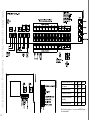
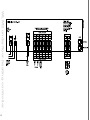
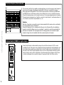
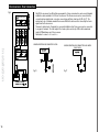
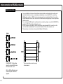
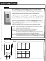
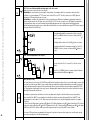
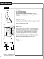
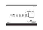
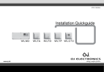
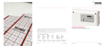
57641A 11/08 (DJU)
Installation Manual
WLM2
www.oj.dk
1
WLTA WLTD WLTP WLCT2
Congratulations
Congratulations with you new control system for
underfloor heating and cooling.
The control system has been developed to provide a
temperature control system for room heating and cooling,
integrating the switching of primary heating and cooling
sources with the control of water temperature and mixing
devices.
This ensures the best possible comfort conditions and also
reduces energy consumption.
Highlights of the system (depending on equipment):
:: Heating and cooling control for true comfort
:: Humidity sensor to prevent condensation on floors
:: Energy saving comfort with adaptive function
:: Area control for easy operation
:: Flexible installation for wired and wireless connection
:: Network communication for large applications
:: Easy installation with plug and lead connections
:: Optional weather compensation
2
BR-0965-A10
Installation Manual
CONTENT
WLM2 Underfloor Heating Controller...................4
Description.............................................................................7
Product Programme...............................................................7
Technical Data........................................................................7
Environment...........................................................................8
Recycling of obsolete appliances..........................................8
Configuring the Total System.................................................8
Installation...............................................................9
Electrical Installation .............................................................9
Boiler Demand . .....................................................................9
Pump Output . .....................................................................10
Free relay function (X-OUTPUT)...........................................10
Thermal Actuators [Thermoheads].......................................12
External Switch (TIMER) for night setback...........................12
Room sensors - Bus Connection ........................................13
Channel Setting....................................................................14
Room sensors - Wireless setup...........................................15
Supply water temperature sensor and mixing valve............16
Special Functions.................................................17
Creating a network...............................................................17
Using cooling functions........................................................18
Domestic hot water control..................................................19
Radiator control....................................................................20
2 step heating.......................................................................20
Commissioning mode .........................................................21
Replacing equipment...........................................22
Replacing a faulty sensor/controller.....................................22
Guidelines and Special Features........................23
Power up recommendations................................................23
Factory Default Settings.......................................................24
Error Indication.....................................................................25
Special Features...................................................27
Temperature & Control.........................................................27
3
Emergency handling............................................28
Exercise of valves.................................................28
Add On Module.....................................................29
Configuring the Total System...............................................29
Outdoor Compensation Module- Type WLOC-19..30
Introduction..........................................................................30
Mounting..............................................................................30
BUS CONNECTION - Outdoor Compensation Module.......30
Interconnection of WLM2 products....................31
Interconnections...................................................................31
Waterline Wireless System..................................32
Product Programme.............................................................32
Connection of Master and Receiver.....................................32
Position.................................................................................32
Master..................................................................................32
To set up the system............................................................32
Type WLCT2 (and WLCT2/R/HW/2).....................33
Introduction..........................................................................33
Getting Started.....................................................................33
Daily Use of the room sensor...............................................35
Programming 4-Event Clock Time and Temperature...........36
Advanced Settings and Read-out........................................37
Reset to factory Settings - room controllers........................41
Waterline Room sensors ....................................42
Introduction..........................................................................42
Set-up...................................................................................43
Setting of Room Temperature..............................................44
Setting of Room sensor Operating Mode............................44
Limit Sensor - WLTD and WLCT2........................................45
WLM2 Underfloor Heating Controller
To Control X-OUTPUT for:
DIP-5
DIP-6
DIP-7
Boiler pump
OFF
OFF
OFF
High limit zone valve
ON
OFF
OFF
Cooling device/module
OFF
ON
*
Cooling device/module
alternative
ON
ON
*
Differential thermostat
OFF
OFF
ON
*ON = Actuator output no.1 is used as an ON/OFF signal for a dehumidifier
4
WLM2 underfloor heating controller
To Control X-OUTPUT for:
DIP-5
DIP-6
DIP-7
Boiler pump
OFF
OFF
OFF
High limit zone valve
ON
OFF
OFF
Cooling device/module
OFF
ON
*
Cooling device/module
alternative
ON
ON
*
Differential thermostat
OFF
OFF
ON
*ON = Actuator output no.1 is used as an ON/OFF signal for a dehumidifier
5
WLM2 underfloor heating controller
6
Description
WLM2 underfloor heating controller
7
Type WLM2 underfloor heating controller is suitable for connecting multiple room Room sensors and
electric actuators (thermoheads) for an underfloor or radiator based heating system.
Room sensors requiring a 230V or 24V live & neutral must NOT be connected.
Only OJ Room sensors type WLxx that are prepared for 2 wire or wireless communication
can be used.
Product Programme
Product
Thermo Heads
Type
Master for 8 zones Master for 8 zones with display
Master for 8 zones Master for 8 zones with display Add-on module for 6 zones
Add-on module for 6 zones
230V AC
230V AC
24V 24V 230V AC
24V
WLM2-1BA (basic system)
WLM2-1FS (full system)
WLM2-3BA (basic system)
WLM2-3FS (full system)
WLM2-1AO
WLM2-3AO
Technical Data
TECHNICAL DATA
Power Supply.............................................................................................. 230V AC +10/-15%, 50 HZ
Max load pumps and Thermal actuators ........................................................................................ 10A
Boiler relay.........................................................................................................Volt free signal. Max 4A
Main pump (free relay) . ....................................................................................Volt free signal. Max 4A
Secondary pump..............................................................................................230V AC, 50Hz Max. 4A
Thermal actuators:
WLM2-1BA......................................................................................................................... 8 x 230V
WLM2-1FS......................................................................................................................... 8 x 230V
WLM2-1AO......................................................................................................................... 6 x 230V
Max. 2A per output. Max. 5A in total
WLM2-3BA........................................................................................................................... 8 x 24V
WLM2-3FS............................................................................................................................ 8 x 24V
WLM2-3AO........................................................................................................................... 6 x 24V
Max. 10VA per output. Max. 35VA in total
Optional External Switch (Timer) for night setback.......................................... Open terminals for NSB
Closed terminals for day operation
Room sensor Bus 2 wire low voltage.................................................... bus signal from Room sensors
RJ14 interconnection cables....... CAT5 STP, max 300 meters between masters and 600 meters in total
Additional data for WLM2-1FS & WLM2-3FS (not applicable to the basic version)
Application sensor and Limit sensor................................ NTC type ETF-1899A for water temperature
Control signal for mixing valve actuator..................................................................................0-10V DC
Power supply for mixing valve actuator.....................................................................24V AC. Max 6VA
Environment
WLM2 underfloor heating controller
Please help us to protect the environment by disposing of the packaging in accordance with the
national regulations for waste processing.
Recycling of obsolete appliances
Appliances with this label must not be disposed off with the general waste.
They must be collected separately and disposed off according to local regulations.
Configuring the Total System
Each master module is capable of controlling 8 heating zones, each of which may use one or more
loops of piping, with one or more thermal actuators.
These zones are referred to later in this instruction as channels 1 to 8. If you wish to control more
than 8 zones, it is necessary to install an ADD ON (AO) module, each of which can provide another 6
outputs. The AO module then controls channels 9 to 14,
Type WLM2-1BA and WLM2-3BA
Green:
Power supply connected
Red:
Night setback active
Red flashing:Indicates error
Secondary UFH pump is running
Boiler enable signal is activated
1..8
Type WLM2-1AO and WLM2-3AO
8
X-Output function is active (see section: “Free relay function”).
Type WLM2-1FS and WLM2-3FS
Zone 1 to 8 indicating heating is on
Installation
Fit the WLM2 master to a suitable wall. It will generally be found more convenient if the unit is within
0.8 metre of the manifold, as most thermal actuators are supplied with 1m cables. Cables can be run
on the surface into the terminals using either the cable releases in the cover or by pressing out the
cable entries in the lower part of the cover.
Electrical Installation
Fig. 3
PLEASE ENSURE THAT ALL WIRING IS CARRIED OUT IN ACCORDANCE WITH
LOCAL ELECTRICAL REGULATIONS.
When wiring is completed, fit the cover on the master using the screws provided.
Mains supply
WLM2 requires a 230V AC mains supply connected to the terminals marked L, N, & E.
Boiler Demand
Fig. 4
The master has a volt-free relay output that can be used to control a boiler, or to open a
motorised valve.
A) To control a boiler that requires switching of the live supply, take a link from L (230V) to the
terminals marked BOILER - B1. Connect the boiler L to the terminal marked BOILER – B2.
Connect the boiler N terminal to the N terminal on the master, and the boiler E to the master
terminal E. (see fig. 7A).
B) To control a boiler that has a pair of dedicated terminals for remote switching (e.g. by a Room
sensor), connect these terminals to B1 and B2 on the master. B1 and B2 terminals are “volt free”
so they can be used for both a 240V and a 24V circuit from the boiler.
9
C) To control a motorised valve:
Many motorised 2 port, spring return valves, have wires coloured BROWN and BLUE for power
connections. In this case BROWN goes to the terminal B2 under the heading BOILER and BLUE
goes to the N terminal of the master. Then a link from L (230V) to the terminals marked “Boiler
B1”. The boiler relay will be energised after a delay of 10 sec after the start of the main pump.
Basic versions without display. Type WLM2-1BA and WLM2-3BA The boiler relay will stop if
there is no heat demand measured by the Room sensors.
Versions with display. Type WLM2-1FS and WLM2-3FS.
These units have supply water temperature control, and the boiler relay will be ON once the
control valve has reached 20% open, and will remain on as long as a heat demand exists.
Pump Output
Installation
Fig. 5
The master has an output for the underfloor circulating pump (secondary pump). The output will be
energised after a 180 sec. delay when any connected room sensor calls for heat. The delay is to
allow time for the thermal actuator to start opening.
The 230v AC pump can be connected directly to terminals L and N under the heading “Sec. UFH
Pump”. Connect the pump E (Earth) terminal to E (earth) on the master. The maximum pump load
must not exceed 4 amps , 230v at start up. There is an overrun period of 1 minute after the demand
for heat from the room sensor disappears.
Delay times:
Secondary UHF pump
180 sec.
X-output (configured as main pump) 190 sec.
Free relay function (X-OUTPUT)
Fig. 6a
All WLM master have a relay which can be
utilized for a number of different purposes.
The relay is a volt free output and is positioned
on the PCB as shown on the drawing.
The function of the relay is determined by the
setting of the DIP-switches.
The functions that the relay can perform, and the
appropriate DIP-switch settings, are as follows:
10
To Control X-OUTPUT for:
DIP-5
DIP-6
DIP-7
Boiler pump
OFF
OFF
OFF
High limit zone valve
ON
OFF
OFF
Cooling device/module
OFF
ON
*
Cooling device/module
alternative
ON
ON
*
Differential thermostat
OFF
OFF
ON
*ON = Actuator output no.1 is used as an ON/OFF signal for a dehumidifier
The X relay output is volt free as shown in fig 8a. If the relay is required to be used as a L & N switch, connect a
link wire from mains L to C1, connect the device L to C2, and the device N to mains N.
Boiler pump:
Where a boiler primary pump is required to be switched on from the master, the relay output can be used for this
purpose. The relay will be activated 10 seconds after the UFH circulating pump has started.
High Limit Zone Valve:
This function is used where an additional protection is required to prevent boiler water entering the underfloor
system, when the system is off or when the supply water exceeds 65 C.
An additional sensor (ETF-1899A) called ‘Application Sensor’ as shown in fig. 8b and a zone valve is connected
via the X-output (see example fig. 8c.)
Installation
11
Cooling device/module:
The relay output can be used to provide a volt free signal to a heatpump, or to a K-MOD switching module
where a chiller is utilized to provide the cooling water. The relay is on when there is a cooling demand. (For more
information see the section “Using cooling functions”.)
Fig. 6b
Cooling device/module alternative:
The relay output is always on in cooling mode and off in heating mode. (For more information see the section
“Using cooling functions”.)
Differential thermostat:
The relay output can be used as an output that enables an alternative energy sources like solar energy.
To use this, besides the supply water sensor, an additional sensor (ETF-1899A) called ‘Application Sensor’ is
needed in the system, to detect the temperature in the water storage cylinder of the alternative energy source.
If the system detects that this temperature (via the Application Sensor) is more than 3°C higher than the supply
water temperature it activates the X-relay to select the alternative energy source by a valve and/or a pump.
Fig. 6c
Thermal Actuators [Thermoheads]
Fig 6
Installation
12
These actuators are fitted to the underfloor heating manifolds and control the supply of water through the
various loops. The voltage of the thermal actuators, 230V or 24V, must correspond to the master.
Master type WLM2-1BA and WLM2-1FS are for 230 V thermal actuators, and master type WLM2-3BA
and WLM2-3FS are for 24V Thermal actuators. Up to 8 different zones can be controlled by the master.
Connect the thermal actuators on the loop(s) for each zone to the corresponding terminals on the master.
Thermal actuators belonging to zone 1 must be connected to output terminal 1, and thermal actuators for
zone 2 must be connected to output terminal 2, etc, etc.
Guideline
More than 1 head can be connected to a single terminal, provided that the heads are to be controlled by
the same room Room sensors / Controllers.
Connect the Brown wire to the L terminal, and the Blue wire to the N terminal. When the installation is
complete, check that the Room sensor in e.g. room(zone) 1, operates the correct thermo actuator(s) for
that room on the manifold. If the heads appear to be in the wrong position on the manifold, it may be
simpler to change them on the manifold, rather than reconnecting them on the master.
External Switch (TIMER) for night setback
Fig 7
From factory the master is delivered with a jumper in the switch/ timer terminals I & O. The current
operating set point of the master can be changed from the day temperature into night temperature, and
vice versa by using an input from an external switch or timer. The input must be a volt free switch, and
will need to open circuit for night temperature and close circuit for day temperature. When the external
switch or timer is used to switch to night setback, this will override any time settings in a WLCT Room
controller, including any Room sensors that are part of a group allocated to that Room controller.
Room sensors - Bus Connection
Fig 9
Installation
13
Only OJ Room sensors type WLxx that are prepared for 2 wire communication can be used. Standard
installation cable, maximum 2 x 0.25 mm2 can be used. The Room sensors can be connected in the
conventional star wiring format, or in a bus connected mode (Daisy chain) see fig 10 + fig 11. The
master has 4 sets of terminals marked Room sensor BUS that can be used for connecting the 2-wire
signal from the Room sensors.
There are 4 identical sets of terminals for convenient installation. Any Room sensor can be connected
to any pair of terminals. The total length of the 2-wire system can be up to 300 m with a maximum
length of 100mbetween any 2 Room sensors.
Remember to connect + to + and – to – .
SENSORS/CONTROLLERS CONNECTED IN STAR
SENSORS/CONTROLLERS CONNECTED IN BUS MODE
(DAISY CHAIN)
Fig 10
Fig 11
Channel Setting
Fig 10
Each Room sensor can be selected to operate a specific output which in turn controls the thermal
actuators on the manifold. Under the front cover of the Room sensor, a selector can be accessed,
and the number of its output (its CH channel) can be set with a screwdriver. (See fig 10) Up to 14
channels can be set on the selector, and there are two auxiliary channels. (see later). A WLM2
master has 8 outputs and additional slave module 6 outputs, and can be connected creating a
system of 14 individual zones.
Please note that channels 10 to 14 are marked as A through E on the selector,
Installation
A Room sensor set for CH1 will activate the thermal actuator connected to output 1 on the master.
The channel number can be selected without any power connected to the system. The channel of
the Room sensor can be changed afterwards if needed.
If two Room sensors are placed in the same room and set to the same channel, the temperature
control will work according to the average temperature of both Room sensors.
Channel 0:
Each Room sensor is delivered with the switch in position 0 ensuring that it must be set to operate
correctly. Channel 0 can also be used for a Room controller controlling a group of Room sensors
where the control position should be somewhere central, e.g. the kitchen, rather than in the area
where the Room sensors are installed. Setting it to Ch 0 means that times and temperatures are
set on the WLCT2 for the group, but that the WLCT2 will not control a specific output itself.
Channels 1..14:
A Room sensor set for channel 1 will activate the thermal actuator connected to output 1 on
the master. If several Room sensors are set to the same channel number, they will control in the
following way,
- The actual room temperature is calculated as an average.
- The room temperature set point is calculated as an average.
- If a limit sensor is connected to the Room sensors
The lowest value of any Limit sensor is taken as the MIN Limit Temperature.
The highest value of any Limit sensor is taken as the Max Limit Temperature.
Channel 15: (position F on the switch) Party and vacation function.
Special function. Further instructions in “Special Features”.
Testing the system: See ”Guidelines and Special Features – Power up recommendations”
14
Room sensors - Wireless setup
Fig 12
Where wireless Room sensors/controllers (WLTx-29) are being used is necessary for the WLM2 master to
“learn” that the Room sensors/controllers are communicating correctly.
To achieve this:
1. On master, switch on DIP-3 to activate learn mode:
2.
Installation
3. Switch off DIP-3 to de-activate learn mode.
Fig 13
Button learning mode
15
All wireless Room sensors/controllers now have to be initialized:
Room sensors (WLTA, WLTD, WLTM, WLTP) by pressing the internal init button
(Button learning mode) until a beep is heard. (see fig. 12)
Room controllers (WLCT2) by pressing the pin hole button with the clock symbol until a beep is heard. (see fig. 13)
Supply water temperature sensor and mixing valve
Fig 11a
Installation
16
Supply water temperature limit sensor
This feature is available on the full system masters WLM2-1FS & WLM2-3FS.
The limit sensor is directly connected to the master at the terminals marked supply sensor. Sensor
type ETF-1899A must be used.
The temperature sensor should be placed on the supply water pipe to the underfloor heating
system, If a limit sensor is installed, without a weather compensation module (WLOC) the master
will control the design supply water temperature. The factory default setting can be changed via the
display.
If a weather compensation module (WLOC) is added to the system, the master will vary the supply
water temperature setting based on the outdoor temperature. A standard compensation curve
has been programmed at the factory. If needed the curve can be changed, see separate USER
MANUAL, MASTER TYPE WLM2.
Mixing valve actuator control
Control of a mixing valve actuator is possible using the digital masters WLM2-1FS and WLM2-3FS
The actuator must be 24Vac powered (max 6VA) and positioned via the 0-10V DC signal, and
should be configured so that it closes the valve if there is no heating demand (0Vdc signal). The
control signal can be reversed to 10-0V via the master menu system if required.
Control action of the mixing valve actuator is P + I and the parameters can be changed if required in the master menu system.
Please contact the supplier for further instructions.
Fig 11b
Special Functions
Creating a network
Fig 12a
In large buildings with more than 14 zones where multiple manifolds are
utilized, it is possible to use multiple masters to create a single network.
One master must be defined as the “network controlling master” by
setting both encoders to zero (see fig.12a,12b).
Subsequent masters (up to nine) should be connected as a “string”,
where they will all use a common pump.
If more than one pump is used, a separate string should be created for
each pump (see fig.12a).
On the first string all left hand encoders must be set to 1, and the right
hand encoders should be set in sequence from 1 to 9.
On the second string of masters all left hand encoders should be set to
2, and the right hand encoders again should be set in sequence from 1
to 9. This numbering can be continued for up to 15 strings.
All Masters are interconnected using special cable via the RJ14 socket 1 or
2. (For further information see section “Interconnection of WLM2 products”.)
All masters must be connected in a daisy chain connection, and NOT in
a star connection (see fig.12c).
Fig 12b
An FS master can be used as the “network controlling master” for
central mixing control of supply water and boiler switching.
Switching between cooling and heating can be done for the whole
network on the “network controlling master” using the WLAC-1 interface
module connected to the thermostat bus.
Time and temperatures for the whole network can be controlled by a single
WLCT2 connected to the “network controlling master” if the WLCT2 is set
to channel F.
Fig 12c
17
• A network must always contain a network controlling master.
• On masters set to the same string (same setting on the left encoder), all pumps, boiler and valve outputs will act simultaneously enabling the use of a common pump on each string.
• If only one UHF pump is used in a network, DIP-8 on the network controlling master can be set to
“ON” enabling the UHF-pump output on this master to control a common pump for the whole system.
• All masters in a network follows the same synchronized timing for actuators, pumps, boilers and mixing valve output.
• If a lower supply water temperature is needed on one of the strings, the first master on this string can be a FS master with a local mixing valve and supply water sensor attached.
Special Functions
• On FS masters a special menu is available on the network master when a network is detected.
With this menu it is possible to check the network. Please refer to the USER MANUAL for further instructions.
Note: To test a network please refer to section “Power up recommendations”.
Using cooling functions
In addition to controlling heating, all WLM2 masters have the ability to control the system for cooling.
• To enable the cooling function an interface module WLAC and humidity sensor WLH have to be
connected.
• To use the X-relay as a cooling signal controlling, a chiller, a reversible heat pump or
diverting valves, please refer to the section “Free relay function (X-OUTPUT)”.
• On BA masters it is also necessary to install a sensor (ETF-1899) on the return water pipework
from the floor for dewpoint control. The sensor must be connected to terminal 49 and 50.
Using the WLAC-1 module:
• The WLAC must be fixed in a convenient position for the user, and connected to the sensor/
controller bus as shown in the drawing.
•
If a BMS system in being used for the heating/cooling decision, the volt free BMS signal (EXT) should
be connected to the WLAC but the slider switch on the right side of the WLAC must be set to the
heating position (in this situation the BMS signal has priority and we recommend that the slider
toggle be removed to avoid incorrect overriding)
Humidity sensor WLH-19:
• By using the humidity sensor WLH the system limits the formation of condensation on floor
surfaces due to high humidity.
•
18
Type WLH-19
The WLH must be fixed in a room that represents the general humidity level in the building, and
connected to the sensor/controller bus (more than one WLH can be used if necessary e.g. on
separate floors of the building). Where more than one humidity sensor is used, the master will take the reading of the sensor detecting the highest DEW point level for the controlling action.
• If a dehumidifier is being used it can be connected via a relay using number 1 output on the master
and setting DIP-7 to “on”. (Note: This output gives either 24Vac or 230Vac depending on the WLM2 master type. Channel number 1 cannot be used for Room controller control in this situation)
• When cooling is enabled the cooling set point will be pre-determined by the master and will override any settings in any Room controller to ensure optimum energy efficiency. (The cooling set point will be +3C above the master day set point)
Domestic hot water control
Special Functions
It is possible to control the domestic hot water temperature with a special controller (WLCT2/HW) to
ensure optimum energy saving.
A hot water sensor is connected to the controller and measures the temperature in the storage cylinder.
A zone valve is then controlled via the WLM2 master, which in turn activates the boiler on demand.
• Install the hot water senser (ETF) on the hot water take off pipe immediately above the storage
cylinder. Use the fixing strap to mount it tight to the surface.
• The WLCT2/HW must be fixed in convenient position for the user
• Connect the hot water controller WLCT2/HW to the WLM2 master using the sensor/controller bus.
• Connect the hot water sensor to the controllers sensor terminals.
• Connect the hot water zone valve to an output on the WLM2 master and set the channel number
on the hot water controller to the corresponding number.
The hot water controller is available in wired or wireless version.
Note: When the WLCT2/HW calls for heat it does not start the circulation pump on the under floor
heating system
Type
WLCT2/HW
19
Radiator control
It is possible to control a radiator circuit room temperature with a special controller
(WLCT2/R) to ensure optimum energy saving.
The controller measures the temperature in the room, and a zone valve is then controlled
via the WLM2 master, which in turn activates the boiler on demand.
• The WLCT2/R must be fixed in a convenient position for the user, but which is representative of the room or area temperature.
• Connect the controller to the WLM2 master using the sensor/controller bus.
Special Functions
• Connect the radiator zone valve to an output on the WLM2 master and set the channel number on the Room controller to the corresponding number.
• The special Radiator controller is available in wired or wireless version.
Type WLCT2/R
Note: When the WLCT2/R calls for heat it does not start the circulation pump on the
under floor heating system. While the System is in Cooling mode, all radiator circuits will
be off.
2 step heating
It is possible to control a secondary heat source in a room (e.g. a
backup radiator), use the special mode in the WLCT2/2 controller.
In addition to the primary underfloor heating output, this WLCT2/2
controller is able to control a second output as a boost function,
which will be activated only if the temperature cannot be achieved by
the underfloor heating within a preset time period.
• The WLCT2/2 must be fixed in a convenient position for the user, but which is representative of the room or area temperature.
• Connect the controller to the WLM2 master using the sensor/
controller bus.
• Set the channel number on controller to correspond with the output on the WLM2 master that is connected to the underfloor
heating actuator.
Type WLCT2/2
• The next numerical output on the WLM2 master MUST be used for the secondary/boost function.
• While the system is in cooling mode, step 2 will be disabled
• The 2-step controller is available in wired or wireless version.
20
Note: To avoid overloading the WLM2 master, we recommend that the
secondary output is used as a signalling function for a remote relay.
Please refer to the technical information.
Commissioning mode
Supply temp.
Digital masters include a special “commissioning mode”, which allows the temperature of the supply
water to be controlled to assist the drying out of a newly laid concrete floor.
Max.
To start this function:
• Set DIP-4 to “on”.
• This will set the supply water temperature at 23c for three days and will fully open all the manifold
actuators.
23˚C
Special Functions
21
• Then for a further four days the water will be supplied at the maximum supply water temperature,
as set in the WLM master menu, and during this period the manifold actuators will remain fully open.
1
2
3
4
5
6
6
• When the WLM master is operating the commissioning function this is indicated by the output
LED’s flashing in rotation and with the word “commissioning” flashing in the display.
• The commissioning function time periods are paused if the power supply is interrupted.
• Should you need to restart the commissioning from the beginning, switch DIP-4 to “OFF” and
back to “ON”.
• To de-activate the function switch DIP-4 to “OFF”.
• After 7 days the commissioning mode is ended and normal operation is re-established (even with DIP-4 on)
Note: This function conforms to BS/EN-1264 part 4.
Replacing equipment
Replacing a faulty sensor/controller
1. Identify the sensor/controller to be changed by the blinking output LED.
2. Switch OFF power to the master
3. Change the sensor/controller.
Important: Set the channel selector on the new sensor/controller to the same channel as the defective sensor/controller that is replaced
4. Switch ON power to the master
5. Set the master into learnmode and set DIP-3 to ON.
6. On wireless sensor/controller now press the button on the sensor/controller.
On hardwired sensor/controller go to step 7.
7. Check that the corresponding output LED has changed from blinking to permanently ON.
8. Reset the DIP-3 to OFF.
For any other changes in the system use the quick guide and start the install sequence from the
beginning.
22
Guidelines and Special Features
Power up recommendations
When all connections are complete we highly recommend that the connections between the sensors and
the thermo heads are tested by following the sequence below:
System check:
Correct operation of the system can be checked using a special “Install Mode”.
This enables the installer to individually test and prove each output.
Testing the system:
1.
Switch on DIP-3 to activate learn mode: - power light will blink quickly
TOTAL X
2.
Each red channel light on the master should now be lit if a sensor/controller is present on that channel.
3.
Switch off DIP-3 to de-activate learn mode again – power light stops blinking.
4.
Turn all adjustable temperature settings on the sensor/controller to minimum.
5.
Switch on DIP-1 on the master to activate install mode (Install mode will be active for 2 hours).
(Pumps, boiler, mixing valve and actuators should now be off)
6.
Turn the temperature setting on the adjustable sensor/controller in room 1 to maximum.
The red channel 1 light should be lit and the actuator on output nr. 1 will be activated, and will
open after 1-3 minutes, depending on the type of actuator.
Important: If the sensor/controller is of a wireless type a delay of up to 5 minutes may occur before
the channel light becomes illuminated. Boiler will not operate during test mode, unless DIP 2 is activated, see step 9 below.
7.
Check that the UHF pump is running and the mixing valve (only FS master) opens.
8.
Repeat step 2 on all rooms.
9.
Boiler test function: Switch on DIP-2. This closes the boiler start relay contacts for 1 minute.
10. To end all tests:
- Switch off DIP-1 to deactivate Install mode
- Switch off DIP-2 to deactivate boiler test.
- Set all temperature knobs to default positions
Room sensors (WLTA, WLTD, WLTM, WLTP) to zero (center position).
Room controllers (WLCT2) recommended to 21c.
- Set all override switches on WLTM and WLTD room sensors to automatic position (clock symbol).
23
Testing a network:
If a network of masters has been set up, the communication between these must be tested.
When the slave masters are in install mode (DIP-1 is ON) the power LED will flash shortly every time a
communication is detected (approx. every 3 sec). On an WLM2-xFS network master there is a menu
entry that gives a possibility to check how many masters are present on the system and if they have any
errors. (please refer to the userguide about the menu)
The system is now operating automatically.
Factory Default Settings
Additional information
Guidelines and Special Features
24
Master
Settings
BA/FS
Day temperature
21˚C
Night temperature
18˚C
Off temperature
5˚C
Floor Limit temp high
27˚C
Floor Limit temp low
17˚C
FS
Factory
settings
Max water temperature
Own
settings
Master
Settings
BA/FS
Cooling mode
55˚C
Weather compensation
Outdoor temperature
-3˚C
Cold (winter)
Water temperature
45˚C
Weather compensation
Outdoor temperature
20˚C
Warm (summer)
Water temperature
25˚C
Factory settings
Day cooling
temperature
Day heat temperature + 3°C
Night cooling
temperature
Day cooling temperature + 3°C
DEW point safety zone
DEW point + 3°C
Room temperature
control
PI - control
P = 4°C
I = 90-180 sec
K-factor = 0.1
Floor Limit
temperature
control
P - control
P = 4°C
Adaptive PWM
control
Max allowed Room
temperature fluctuation
+/- 0.5°C
Self adjusting
(adaptive) PWM time
interval limits
15 – 45 minutes
Max number
of connected
sensors
Wired and wireless
24
Sensor timeouts
Wired
300 sec.
Wireless
10000 sec. (2h 45 min)
Minimum cooling
supply water
temperature
16°C
PI - control
P = 20°C
I = 300 sec.
K-factor = 0.05
FS
Supply water
temperature
control
(5 min)
Error Indication
During normal operation the power LED will be ON when the master control is energised. The red output Channel LED’s
(1 to 8 on the master, and 9 to 14 on the add-on module) will indicate if the channel output relay is ON/OFF.
Guidelines and Special Features
An error / fault message is shown by flashing the power LED or one of the red output Channel LED’s. From the number of flashes
on any one LED, the problem can be diagnosed, and identified from the following:
The error number will be indicated by the number of flashes, with a pause of less than a 1/2 second between the flashes. The indication will be followed
by a pause of 2 seconds, following which the sequence will be repeated. The failure code can also be seen in the service menu on WLM2-FS MASTERS
(submenu 2).
Flashing Power LED (Red and green)
Communication to the network has errors. On the network master it tells that one or more masters are not communicating. On a network slave it tells that
communication to the network master is missing.
Flashing Power LED (Red)
E1, 1 flash
One or more room sensors, room controllers, WLH, WLAC that are set to channel 0 or channel 15 are no longer sending data to the master control. The fault is corrected by replacing the room sensor. The master will need to be HARD RESET (see next page)
(NOTE: If the room sensor is of the WIRELESS type, the error/fault message could be an indication that the power has failed,
and that the internal battery of the room sensor needs to be replaced)
E2, 2 flashes
One or more room sensors have been set to a channel number which does not exist in the system. For example, the message will occur if the units are set to channels 9-14 and the required add on (AO) module are not found in the system. The error is corrected by setting the channel number of the room sensor to a channel that does exist within the installed master/add on module system.
E3, 3 flashes
Application sensor defect. The fault is corrected by changing the temperature sensor. If the sensor has been removed deliberately to
change the operation of the system, follow the HARD RESET instruction see next page.
E4, 4 flashes The outdoor compensation module (WLOC) is defective. The fault is corrected by changing the outdoor compensation module.
If the module has been removed deliberately to change the operation of the system, follow the HARD RESET instruction see next page.
E5, 5 flashes
The external Supply limit sensor (type ETF-1899A) is defective. The fault is corrected by changing the temperature sensor. If the
sensor has been removed deliberately to change the operation of the system, follow the HARD RESET instruction see next page.
E6, 6 flashes
E7, 7 flashes
Internal overheating. The master has its own internal safety temperature protection system. The problem is corrected by improving the ventilation around the master module.
E8, 8 flashes
The communication to the AO module has been lost. The fault is corrected by re-establishing the connection to the AO module or by changing the AO module if it is defective - or if it has been deliberately removed, with a HARD RESET.
E9, 9 flashes
Indicates total number of input units exceeded. Please refer to factory or your local service engineer.
Defective internal overheat sensor. The Master will control as normal, however the protection against internal over heating is no
longer active. The fault can only be corrected by replacing the master module.
E10, 10 flashes No connection to wireless receiver, type WLRC2-19.
E11, 11 flashes Step 2 on 2-step controller (WLCT2-X9/2) is used by another room sensor/controller.
25
Only one error/fault condition can be shown at a time. If more than one error occurs, they will be prioritised in the shown sequence (E1, 2, 3…).
Flashing output LED (red):
The appropriate output channel LED can flash, indicating that the room sensor or room contoller on that channel has a fault/error. The failure code can
also be seen in the service menu (submenu 2a).
Guidelines and Special Features
26
E1, 1 flash
The master has lost communication to the room sensor. The fault is corrected by re-establishing the connection to the Room
Sensor and the fault condition will be automatically reset once correct communication is resumed. If the room sensor is
defective and has to be changed, or if it has been deliberately removed, it is necessary to make a HARD RESET. (NOTE: If the
room sensor is of the WIRELESS type, the error/fault message could be an indication that the power has failed, and that the
internal battery of the room sensor needs to be replaced)
E2, 2 flashes
The internal sensor in the room sensor/controller is defective. The fault can only be corrected by replacing the room sensor/
Controller. Remember to make a HARD RESET after installing the new room sensor/controller.
E3, 3 flashes
The limit sensor on the room sensor/controller is defective. Replace the faulty sensor. Reset is NOT required.
E4, 4 flashes
Defective WLCT2 room controller. If a room controller operating a group of room sensors becomes defective, the remaining
room sensors will continue control within the maximum and minimum limits programmed into the Room controller.
E5, 5 flashes
Two or more room controllers are trying to control this output. Check “AREA” setting on the room controllers.
E6, 6 flashes
Channel output number one is configured as a dehumidifier output, error caused by a room sensor/controller also being set to control this output.
RESET
There are 2 different reset actions that can be used.
HARD RESET
If the ‘✓’ button is pressed for 5 seconds, a HARD RESET will be initiated. (Indicated by all the red output LED’s(1-8) lighting in sequence). This reset
will remove from the system any room sensor unit with a defective input sensor, or a defective AO module. The fault message will be reset but the
defective items will no longer participate in the system. To add or replace a new unit, please refer to “Replacing equipment - Replacing a faulty sensor/
controller”. To erase the identity of the defective component from the master memory a HARD RESET must be performed Hard resets do not alter the
temperature settings already programmed into the master control.
FACTORY RESET
If the (√ ) button is pressed for more than 15 seconds, a total factory reset will be initiated. This is indicated through flashes of channel LEDs 1,3, 5 and
7 alternating with channel LEDs 2, 4, 6 and 8 (while the “√” button is pressed).
A factory reset will put all programmed temperature settings back to the factory defaults. It will also remove all room sensors/Controllers from the
master memory, and reset the system to accept only those room sensors/Controllers that are functioning correctly.
To reconnect room sensors/controllers, please refer to “Replacing equipment - Replacing a faulty sensor/controller”.
Special Features
Temperature & Control
Temperature Setting
For the master with display, the setpoints can be altered on the display.
Each Room sensor with manual adjustment is capable of increasing or decreasing the preset DAY &
NIGHT setpoints on the master by +/- 4C for the heating zone which it is controlling.
The Room controller WLCT2 has its own DAY & NIGHT temperature settings that can be set separately,
and if manual Room sensors are attached to its ”group” these will operate to the same settings as the
WLCT2, but still with the possibility of local ±4°C adjustment.
Override Facility
CHANNEL F OPERATION (Channel 15)
By fitting a WLTM2-x9 sensor to any WLM2 system, and setting the hex-coder to Channel F, it is possible
to override all the automatic time and temperature functions of the master control, including those areas
independently controlled by a WLCT2-x9 room controller, with a single override function. This can be
especially useful for long periods where overrides would be beneficial, this many include holidays and
periods of un-occupation (where a frost protection level needs to be maintained).
If a WLTM2-x9 has been set to Channel F on your system the override could not be simpler. On the right
hand side of the control is a slide switch with four positions, each one of these affect the functionality of
the system;
AUTO – This will allow the system to run normally from the timings set on the WLM2 master and any
WLCT2-x9’s
DAY - This will keep the system working to the ‘Day’ temperature set point. Any WLCT2-x9’s, or sensor
controlled by them, will not be affected by this operation.
NIGHT - This will keep the system working to the ‘Night’ temperature set point. Any WLCT2-x9’s, or
sensor controlled by them, will not be affected by this operation.
OFF – This will effectively turn the system OFF, there is still a ‘Frost Protection’ level of 5oC in operation
during this function.
If you would like this functionality added to your existing system please consult you installer or service
engineer.
External Timer (see also section “Installation - External switch”)
The external switch or timer function on the master module allows the whole system to be changed from
the DAY Setpoint to the NIGHT Setpoint.
The external switch must have volt free contacts that are OPEN for NIGHT Setpoint, and CLOSED for
DAY Setpoint. The factory fitted link wire is removed when a remote switch/timer is used.
If a WLCT2 Room controller is employed in a part of the system, the external switch action of going to
NIGHT Setpoint will override the Room controller.
27
Emergency handling
Emergency program for room control
- If a Room sensor/controller is defective or if the communication to the unit is interrupted, an alarm will be triggered. Depending on the system configuration the regulation will continue in one of the following ways,
- If there are several units on the same channel which have a room sensor (which is still intact), the regulation will continue as before, however without contribution from the defective unit
- If no valid room sensor/controller is found, the system will run at constantly 20% ON
- If an outdoor sensor is connected, the system will run 40% at 10°C (and Below) decreasing to 0%
at 20°C (and above).
The emergency program is only valid for channels with heat controls, channels with cooling control will
always run at 100% OFF in connection with a defective room sensor’ Should this not read ‘The emergency
program above is only on heating only installations. On heating and cooling installations, and only during
cooling periods, the system will always run at 100% OFF in connection with a defective room sensor.
Emergency program for supply limit sensor
- If the supply limit sensor is deffective, the system will run at constantly 20% on for the valve.
- If an outdoor sensor is connected, the system will run 40% at 10°C (and Below) decreasing to 0%
at 20°C (and above).
Exercise of valves
If no automatic on/off sequence of valves or pumps occurs over a 72 hour period, an exercise of these
components will take place. The actuators will be activated for 3 minutes. The pumps will be started for
10 secs during that period, and the mixing valve, if fitted will be opened and closed.
28
Add On Module
Configuring the Total System
Each master module is capable of controlling 8 heating zones, each of which may use one or more
loops of piping, with one or more thermal actuators. These zones are referred to as channels 1
to 8. If you wish to control more than 8 zones, it is necessary to install an add-on (WLM2-xAO)
module which provides another 6 outputs.
The AO module then controls channels 9 to 14 (9-E on the hex coder).
Connection of master and add on module
Connect the AO-module, using the special cable included in the box.
Mains supply from 230V fused isolator.
The sensor bus can be connected to either the WLM2 master or Add-on module, using either bus
(daisy chain) or star connections. Thermal actuators 1-8 are controlled by the WLM2 master and
9-14 are controlled by the Add-On module.
29
Outdoor Compensation Module- Type WLOC-19
Introduction
Mounting
The masters WLM2-1FS and WLM2-3FS are supplied already prepared for weather compensation
and simply by adding the outdoor compensation module on the 2-wire bus and using the water
temperature sensor on the supply water side, you have a control system for weather compensation.
Preset values are programmed at the factory, but these values can easily be adjusted according to
local needs via the display on the master. See the user manual ”Master with display type WLM” for
changing of the default factory settings
The outdoor compensation module is mounted under the roof eaves, alternative 2-3 m above ground
level. Direct sunlight or any other direct heating source such as air ventilation must be avoided. The
outdoor compensation module is mounted vertically with the cable entry downwards.
BUS CONNECTION - Outdoor Compensation Module
Only OJ Outdoor Compensation Modules type WLOC-19 that are prepared for 2 wire
communication can be used.
Standard installation cable, minimum 2 x0.25 mm2 can be used. The outdoor compensation module
can be connected in the conventional star wiring format, or in a bus connected mode (Daisy chain).
The master has 4 sets of terminals marked Room sensor BUS that can be used for connecting the
2-wire signal from the Room sensors and the outdoor compensation module.
There are 4 identical sets of terminals for convenient installation. Any Room sensor / outdoor
compensation module can be connected to any pair of terminals. The total length of the 2-wire
system can be up to 300 m with a maximum length of 100 m between any 2 Room sensors / outdoor
compensation module. Remember to connect + to + and - to -.
30
Interconnection of WLM2 products
Interconnections
For easy installation, interconnections between master modules, master and add on modules, and
master and wireless receivers, are made by pre-wired plug in connectors (RJ14) For connecting
WLM2 add on modules to WLM2 masters, a plug in connector is provided with the add on module.
A WLRC wireless receiver is also connected to a WLM2 master, using the plug in connector provided
with the receiver.
For connecting a WLM2 master to another master in a network, a plug in connector kit (WLM-NET) is
available. CAT5 STP cable should always be used.
If a kit is not used it is possible to do the connection by using a standard RJ14 connection. In this
case it must be ensured terminal 1 is connected to terminal 1 in the other end and so on.
The same type of connection can be used from Master to AO module.
PLEASE NOTE: The illustration
shows the internal WLM2 master
RJ14 connections 1 to 4.
On the WLM2-xAO module only
connection points 3 and 4 are
supplied.
31
*These connections are not necessary
but are allowed
Waterline Wireless System
Product Programme
Technical Data
Supply Voltage . . . . . . . . . . . . . . 24 V from Master
Distance to master . . . . . . . . . . . . . . . . . . Max 3 m
Enclosure . . . . . . . .... . . . . . . . . . . . . . . . . . . IP 21
Ambient temperature range . . . . . . . . . . 0 to 40°C
Communication Frequency . . . . . . . . . . . 868 MHz
Communication distance . . . . . Up to 30 m inside,
. . . . . . . . . . . . . . . . . . . . . . . . Up to 100 m outside
WLRC2-19 Receiver
Connection of Master and Receiver
B
A
--
+
Blue
Red
Brown
Yellow
The receiver is connected to the master or the add on module using the included cable.
Max distance between the master/add on module and receiver is 3 m. Two receivers can be
connected to a master, or master/add on system, using the RJ sockets provided. Additional
receivers can be connected if necessary – please refer to the dealers technical department. The
wiring of the master and add-on module and receiver must be made by using the RJ14 connection
points supplied.
Position
Do not place the receiver inside a metal box. In case of communication problems it may be necessary
to move the location of the receiver, or to add an additional receiver.
Master
Connect the receiver to the master, and the system will reconfigure itself for wireless operation.
To set up the system
See Quickguide
32
Type WLCT2 (and WLCT2/R/HW/2)
Type WLCT2 (and WLCT2/R/HW/2)
33
Introduction
The room controller type WLCT2-x9 is a 4 event programmable controller used to control underfloor heating areas
or special features on the WLM2 installation. The standard WLCT2-x9 can be used to programme up to 4 time and
temperature events over a 24 hour period, based upon a 7 day setting. Once a WLCT2-x9 has been fitted the times and
temperatures for the area(s) it controls will no longer come from the defaults set in the main WLM2 master.
In addition to the immediate area of control set, within the WLCT2-x9, and selected via the ‘AREA’ setting contained within its
internal menu, the WLCT2-x9 can control the time and temperature characteristics of other sensor (up to 14) fitted to the WLM2
master, this has been designed to maximise comfort and efficiency and promote energy saving and associated cost savings.
Where the WLCT2-x9 is controlling other areas the +/- 4°C setting of those areas will now operate from the WLCT2-x9
settings, e.g. A WLCT2-x9 is set to 22°C and has been given control over ‘Area 1’, the WLTA-x9 fitted in ‘Area 1’ now has
a control range of 18°C(-4°C) to 24°C (+4°C).
In addition to the standard WLCT2-x9 room controller, you may have fitted to your system one of the following;
WLCT2-x9/2: This control allows the operation of a secondary heat source, for a specific area, as a boost function operating in conjunction with the underfloor heating.
WLCT2-x9/R: This control is used for the control of radiators in a domestic central heating circuit.
WLCT2-x9/HW:This control is used for the production of hot water control within a system.
Upon installation your installer should have set up the WLCT2-x9 control to suit your needs, should you need to change any of the setting please follow the instruction detailed in following pages.
The WLCT2-x9:can be reset by pressing the button marked ‘R’ (see fig 1), this will allow you to return to the factory settings at any time. The default factory settings are detailed after the WLCT2-x9 programming section of this manual.
Getting Started
Fig1
Buttons
A:
B:
C:
Display
Adjustment
down
OK accept
D:
E:
F:
Adjustment
up
Reset to
factory
setting
Pin button
adjust of
clock
Display
Type WLCT2 (and WLCT2/R/HW/2)
34
G
K
H
J
G:
H:
I:
Automatic
mode
Manual
mode
Time and
temperature
J:
K:
Day number
4-event symbol
I
Wake
Out
Night
Home
Setting the room controller into operation
First time power is connected the clock and day will be flashing and must be set. If you need to adjust the
time of the thermostat at a later date, insert a pin into the hole marked
(see fig. 1) for setting of time and
day. Adjustment should be made for change in summer and winter time.
Press the UP (△) or DOWN (▽) buttons to select
the correct hours and press OK button ( ).
Press the UP (△) or DOWN (▽) buttons to select
the correct minutes and press OK button ( ).
Then press the UP (△) or DOWN (▽) button to
select the correct day and press OK ( ) button.
AREA SETUP - see “ArEA” in section “Advanced settings and read-out”
1-7
Daily Use of the room sensor
4-Event Clock Mode
Type WLCT2 (and WLCT2/R/HW/2)
Wake up
Leave
home
Sleep
35
The day has been split into 4 events describing a typical day. When the room sensor is
in this 4-event mode it will change the temperature to the required level automatically
at the programmed times. As standard the room sensor has 5 days with 4 events (two
ON’s and two OFF’s), and 2 days with 2 events (one ON and one OFF).
Return
4-event clock mode/
automatic mode:
Comfort mode:
5 secs.
In automatic mode, the clock function symbol (
indicated. See next page.
) will be
Temporary override
To temporarily override any temperature in the 4-event schedule program, press the UP (△) button once, to show
the temperature in the display, and press UP (△) or DOWN (▽) again to increase or decrease the temperature. The
display will flash for 5 seconds, and will then revert to the time. The override will operate until the next programmed
event when the thermostat will resume the automatic programme.
Cancel comfort mode (temporary override)
To cancel the temporary override, press the OK (
Manual mode:
) and one of the 4-event symbols (
) button twice.
Permanent override:
During holidays, the scheduled 4-event program can be overridden. Press the OK ( ) button, and then the UP (△) or
DOWN (▽) button until the override temperature is set. The set temperature will remain in the display and the unit will
now operate to this temperature permanently.
Cancel manual mode
To cancel the permanent override state press the OK (
) button once, and the unit will resume automatic function.
Programming 4-Event Clock Time and Temperature
Type WLCT2 (and WLCT2/R/HW/2)
36
For each event, the start time and required temperature needs
to be set.
For example, in the morning you wish the heating to start at
07:00 and the temperature to rise to 25˚C. Press OK ( ) button
for 3 seconds and the start time is displayed. Change this to
07:00 with the UP (△) or DOWN (▽) button. Press OK ( ) to
confirm.
The temperature is now displayed. Change this to 25˚C with the
UP (△) or DOWN (▽) button. Press OK ( ) button to confirm.
This action can now be repeated for the second, third and
fourth event.
Press OK (
Day 1 - 5
: Time and temperature
: Time and temperature
These settings will be valid for days 1-5 showing on the display.
To program the days 6 and 7, repeat the above. Days 6 and 7
are usually Saturday and Sunday, and only have two events
(generally morning ON and evening OFF).
The temperature can be set within the range of +5 to +35˚C.
It is also possible to select the heating OFF at that event by
reducing the setting to 5˚C, and then pressing the (▽) once
more.
Note that when programming the “Sleep” time (event 4),
please ensure that this time is before midnight (00:00).
) button for 3 secs. to begin programming
: Time and temperature
: Time and temperature
Day 6 - 7
: Time and temperature
: Time and temperature
Advanced Settings and Read-out
Press both UP (△) and DOWN (▽) buttons together for 3 seconds. INFO is displayed.
Continue pressing the UP(△) button until you reach one of the desired sub menus, PRO, Hi Li, Scal, and ArEA (For explanations, see
below. Select the sub menu with the OK ( ) button.
Type WLCT2 (and WLCT2/R/HW/2)
INFO - Information
The values of the actual measured room temperature and the floor temperature can be seen.
The floor temperature is only shown if a floor sensor is installed.
Press UP (△) or DOWN (▽) button to show the different readouts.
Software version
Room temperature
No changes can be made here. Use the OK ( ) button to end.
Floor temperature
PRO - 4-event sequence
It is possible to change the factory event sequence of Days 1-5 - 4 event, and days 6 & 7 – 2 event. Days 1 to 5 are usually Monday to
Friday, whilst days 6 & 7 are usually Saturday & Sunday. An EVENT is either an ON or an OFF operation. You can select from the following
sequences which are displayed in the form of a code.
4 events 5 days, 2 events 2 days
indicated by Code 4:52
4 events 6 days, 2 events 1 days
indicated by Code 4:61
4 events 7 days
indicated by Code 4:70
2 events 7 days
indicated by Code 2:70
2 events 5 days, 2 event 2 days
indicated by Code 2:52
Select the required sequence with the OK ( ) button.
37
Type WLCT2 (and WLCT2/R/HW/2)
38
Hi Li - Floor sensor. Max and min allowed temperature of the floor surface
A limit sensor can be connected to the room controller.
Max limitation is used for safety to prevent high floor temperatures. For example wooden floor constructions which should not
be allowed to exceed a maximum of 27˚C. The value can be set from 5˚C up to 55˚C. The value can also be set to OFF (adjust the
temperature to 55˚C and push button up once more).
Low limitation is used where the temperature of the floor is required never to fall below the minimum set temperature. Example in
kitchens or bathrooms with tiles. The value can be set from 5˚C up to 55˚C. The value can also be set to OFF (adjust the temperature to
5˚C and push button down once more). Remember the max limit temperature must be set higher than the min limit temperature.
The limit temperatures defined in the room controller will be valid for all the room sensors with limit sensor (type WLTD-19) which are part
of the area allocated to the WLCT2 unit.
The maximum allowable floor temperature setting is shown. Use
the UP (△) or DOWN (▽) button to increase or reduce, and OK ( )
button to accept.
The display will now show LoLi. Press OK ( ) button to continue.
The minimum allowable floor temperature setting. Use the UP (△)
or DOWN (▽) button to increase or reduce and OK ( ) button to
accept.
SCAL - Time and temperature scale selection
You can select either ˚C or ˚F scale, and 12 or 24 hour clock as
follows:
Press UP (△) or DOWN (▽) button to change settings. Confirm the
required scale with the OK button ( ) button.
ArEA - (Group of rooms)
The rooms that are to be set as part of the WLCT2 area will follow the temperature settings of the room controller example, an area could
be the living room, kitchen, and children’s rooms, having a high room temperature requirement during afternoon and early evening, and
a lower temperature during the early part of the day and at night. Each room sensor will have a channel number, designated CH1, CH2
etc. The appropriate channel number of any room sensor is determined by the numbered output on the master control which is actually
switching the valve/actuator for that area.
For example, a system may have the kitchen room sensor operating master output # 4, and the childrens room sensor operating
master output #5. If the WLCT2 room controller is then situated in the living room, and operating output #1, then the WLCT2 need
be programmed to control outputs 1, 4, & 5. (Each room sensor will have been set to operate its appropriate output ch see separate
instructions).
To do this, enter the ArEA sub menu., and press OK ( ) button. CH 1 will be displayed; use the OK ( ) button and then the UP (△) button
to change the setting to ON. Press OK ( ) and CH 2 is displayed. Use the UP (△) button until CH4 is displayed, press OK ( ), and change
to ON. Repeat this for CH 5. All three room sensors will now operate under the control of the WLCT2 room controller.
In total up to 14 Channels can be programmed in this way, and it is possible to have more than a single room controller, each own sub
room sensors operating to its schedule and temperatures.
Type WLCT2 (and WLCT2/R/HW/2)
Set the Channels / Rooms (Ch) to ON if they should follow the settings
of this clock thermostat.
In total 14 channels / rooms can be controlled.
2 st
This menu is only visible on 2 step controllers (WLCT2-x9/2)
2 step – Change of values in 2 step function.
ON
OFF
The display will now show TEMP. Press OK ( ) to continue.
tEn
P
3.0°C
Use the UP (△) or DOWN (▽) button to change the temperature
setpoint in the 2-step function.
( If the actual room temperature is higher than the setpoint minus this
setting, the second output will not be activated)
The display will now show TEMP. Press OK ( ) to continue.
tInE
00:01
39
Press the DOWN (▽) button to activate or de-activate the 2 step
function.
Press OK ( ) to confirm.
Use the UP (△) or DOWN (▽) button to change the time (in minutes)
before step 2 is activated.
(This parameter decides how long the actual temperature is allowed to
remain below the setpoint minus the TEMP setting before the second
output is activated)
Adaptive function
This function enables the thermostat to calculate when it needs to switch ON so that the required temperature is reached at the set time.
With a start time of 07:00 therefore, the thermostat may switch ON as early as 06:00 so that the desired temperature of 2 5˚C is achieved
by 07:00. Without this function set, the thermostat will start to heat at the time you set.
Type WLCT2 (and WLCT2/R/HW/2)
40
Press the DOWN (▽) button to switch between on and off.
Press OK ( ) button to confirm.
ESC - Escape
Press OK ( ) button to end programming and to return to scheduled
programme.
Reset to factory Settings - room controllers
Factory reset:
Type WLCT2 (and WLCT2/R/HW/2)
41
Press the pin button R for 3 secs. and the thermostat returns to
factory settings.
Remember to set time, day and area.
Factory settings
4-event time and temperature
Standard
WLCT2-x9
Special
WLCT2-x9/R
Special
WLCT2-x9/2
Special
WLCT2-9/HW
Time
Temperature
Temperature
Temperature
Temperature
06:00
21˚C
21˚C
21˚C
50˚C
08:00
19˚C
19˚C
19˚C
30˚C
16:00
22˚C
22˚C
22˚C
50˚C
22:30
17˚C
17˚C
17˚C
30˚C
08:00
22˚C
22˚C
22˚C
50˚C
23:00
17˚C
17˚C
17˚C
30˚C
-
4:52
4:52
4:52
4:52
-
27˚C
-
27˚C
-
17˚C
17˚C
-
17˚C
-
2-step time
-
-
-
60 min
-
2-step
temperature difference
-
-
-
2˚C
-
Day 1-5
Day 6-7
Other settings
4-event sequence
High floor limit
temperature
Low floor limit
temperature
Special settings
Waterline Room sensors
Introduction
Fig.1
Waterline Room sensors
Mounting of Room sensor fig. 2
The Room sensor is used for comfort temperature control in rooms. The Room sensor is mounted
on an internal wall with free air circulation about 1.6 m above the floor. Draught, direct sunlight, or
any other direct heating source must be avoided.
Fig.2
Wired Room sensors
Only OJ Room sensors type WLxx that are suitable for 2 wire communication can be used.
Standard installation cable, minimum 2 x 0.25 mm2 can be used. The Room sensors can be
connected in the conventional star wiring format, or in a bus connected mode (Daisy
chain). The master has 4 sets of terminals marked Room sensor BUS that can be used
for connecting the 2-wire signal from the Room sensors. There are 3 identical sets of
terminals for convenient installation. Any Room sensor can be connected to any pair of
terminals. The total length of the 2-wire system can be up to 300 m with a maximum length of
100 m between any 2 Room sensors. Remember to connect + to + and – to – .
Wireless Room sensors
Insert batteries.
Room sensors
connected in star
42
Product programme
WLTP-19/29 Room sensor tamper proof
WLTA-19/29 Room sensor with adjustment
WLTM-19/29 Room sensor with adjustment and mode switch Auto, Day, Night, OFF
WLTD-19/29 Room sensor with adjustment, mode switch Auto, Day, Night, OFF and limit sensor
WLCT2-19/29 Room controller with 4-event clock
Room sensors connected
in chain (Daisy Chain)
Set-up
Fig 3
Waterlilne Room sensors
Please note that channels 10 to 14 are marked as A through E on the selector.
A Room sensor set for CH1 will activate the thermal actuator connected to output 1 on the master.
The channel number can be selected without any power connected to the system. The channel of the
Room sensor can be changed afterwards if needed. If two Room sensors are placed in the same
room and set to the same channel, the temperature control will work according to the average
temperature of both Room sensors.
Channel 0:
Each Room sensor is delivered with the switch in position 0 ensuring that it must be set to operate
correctly. Channel 0 can also be used for a Room controller controlling a group of Room sensors
where the control position could be somewhere central, e.g. the kitchen, rather than in the area where
the Room sensors are installed. Setting it to Ch 0 means that times and temperatures are set on the
WLCT2 for the group, but that the WLCT2 will not control a specific output itself.
Channel 15 (F):
Special function. Further instructions under Section “Special Features”.
To set the Room sensors into learning mode
Standard Room sensors without display: Remove the front cover and push the little leaning mode
button for approx. 2 sec until the Room sensor give a little “bib”
Room controller with display: Press the clock symbol for 2 sec until it says “init”
The Room sensors will now transmit its unique code in the next 30 seconds, and the system has
been set up.
To set up the system for the Master to receive signals from the Room sensors.
(Wireless only)
To set the master into learning mode set DIP-3 to “on”.
The master will now look for new Room sensors that also are in learning mode. Remember to set
DIP-3 back to “off”...RF LEARNINGMODE.. will be shown in the masters with display.
Button learning mode
43
Setting up which Room sensor should work with which thermal actuator
Each Room sensor can be selected to operate a specific output which in turn controls the thermal
actuators on the manifold. Under the front cover of the Room sensor, a selector can be accessed,
and the number of its output (its CH channel) can be set with a screwdriver. Up to 14 channels can be
set on the selector, and there are two auxiliary channels with special functions. A WLM2 master has 8
outputs and additional slave modules each with 6 outputs can be connected creating a system of 14
individual zones.
Setting of Room Temperature
The master is supplied with default temperature settings which are used by all Room sensors
that are connected to the system. In Master WLM2-1BA & WLM2-3BA, the DAY & NIGHT temperature
settings are fixed (see section “Factory Default Settings”) .
In master WLM2-1FS & WLM2-3FS, the DAY, NIGHT and OFF default temperatures are adjustable
through the display.
Waterline Room sensors
On the Master WLM2-1FS and WLM2-3FS, if the temperature setting is changed, then the default
temperature for all the room sensors is changed, but each WLTA, WLTM or WLTD Room sensor is
locally adjustable with its own adjustment knob. With this knob the temperature setting from the
Master can be increased or decreased by 4°C for that specific room.
Automatic switching between DAY and NIGHT temperatures is done by either connecting a separate
timing device to the master, or using a WLCT2 Room controller and allocating Room sensors as part
of its group. It is possible to have two or more WLCT2 Room controllers in the system, with each one
having its own group of Room Sensors.
If the WLTM-19/29 or WLTD-19/29 Room sensors has been allocated to a WLCT2 controlled area,
then when AUTO mode has been chosen with the built-in slide switch, the temperature settings
will be as programmed in the WLCT2 Room controller and not in the master, but the local ±4°C
adjustment is still available.
Setting of Room sensor Operating Mode
Fig. 4
Room sensors type WLTM-19/29 and WLTD-19/29 have a slide switch (see fig. 4) for selecting the mode
of operation of the controller. Four different modes can be selected: Auto, Day, Night and OFF.
Auto: The controller will follow the temperature settings of the master, or if the Room sensors
belongs to a zone group using a WLCT2 Room controller, it will follow the automatic sequence of
temperatures and timings set in the WLCT2.
Day: It will control the room temperature according to the (DAY) setting defined in the master
(typically 21°C).
Night: It will control the room temperature according to the (NIGHT) setting defined in the master
(typically 17°C).
OFF: It will control the room temperature according to the (OFF) setting defined in the master
(typically 5°C). This setting is intended to be a ”frost protection” mode and is used if the room is
to be left unoccupied for long periods.
WLTM-19/29 & WLTD-19/29 are recommended for guest rooms and other infrequently used rooms, as
they allow simple override of the automatic timing sequence.
44
Limit Sensor - WLTD and WLCT2
Waterlilne Room sensors
45
Room sensors/controllers with a limit sensor have a mechanical jumper on the printed circuit board
allowing the limitation to be set for MIN. or MAX. temperature control. If set for MAX., it will have a
temperature setting of 27°C. Set for MIN., it has a setting of 17°C. These temperature are fixed when
used with masters WLM2-1BA or WLM2-3BA unless the Room sensor has been allocated to a zone
group controlled by a WLCT2 Room controller. In this case, the limit settings can be increased or
decreased by accessing the Room controller. The limits then set will apply to all relevant Room sensors
with limit sensors belonging to that group. If the master WLM2-1FS or WLM2-3FS is used, the limit
settings can be changed through the programming buttons on the master.
Mounting of limitation sensor
Jumper mounted: max. limitation
Jumper removed: min. limitation
Fig. 4
Max. temperature limitation is used to protect the floor area from becoming too warm. This may be
required if special floor surfaces (real wood) are used. The sensor should be positioned where it can
read the true temperature of the floor and should always be within the heated area.
Min. temperature limitation is used to keep a floor surface warm, irrespective of room temperature.
For example, water on tiled bathrooms or pool areas with dry more quickly if the floor surface is kept
warm. The sensor should be positioned where it can read the true temperature of the floor and should
always be within the heated area.
For easy replacement we recommend that all floor sensors are mounted in a tube which is placed
between 2 heating pipes. The inner end of the tube should be sealed, and the sensor cable brought
back to the wall edge. If required, the sensor cable can be extended up to 50 m with a standard
installation cable.
WLTM: Use of external room sensor
A remote room sensor can be used instead of the built-in sensor by connecting the jumper across the
two pin bridge on the printed circuit board under the
Room sensor cover. From factory the jumper is “parked” on one pin. Location of jumper see fig. 4.
Technical Data (Wireless)
Supply Voltage Batteries, 2 x AAA Alkaline 1,5 V
Distance to master . . . . . . . . . . . . . . .Max 30 m
Enclosure . . . . . . . . . . . . . . . . . . . . . . . . . .IP 21
Ambient temperature range . . . . . . . . 0 to 40°C
Communication frequency . . . . . . . . . 868 MHz
Communication distance . . . Up to 30 m inside,
Up to 100 m outside
Batteries (Wireless)
The Room sensors use 2 x AAA batteries type
Alkaline. A lifetime of 1-2 years is expected. The
Room sensors are equipped with a low battery
alarm giving a little bip each 5 minutes in case
of low battery. If a Room sensor is defective or if
the communication to the unit is interrupted, an
alarm will be triggered on the master, and the room
will be heated at constantly 20% as safety. The
alarm can be overruled in the next 24 hours. On
the Room controller press the clock symbol for 2
sec. On the other Room sensors remove the front
cover and press the little learning mode button for
2 seconds.
5 7 6 4 1 A
wiltshire, ba12 8sp
Denmark
warminster
DK-6400 Sønderborg
crusader park
Stenager 13B
OJ Electronics UK
OJ Electronics A/S
OJ ELECTRONICS A/S
c/o Robert Bielecki
UL. BRZOZOWA 4
58-160 SWIEBODZICE
www.ojUK.co.uk
www.oj.dk
[email protected]
[email protected]
F.+44 01985 213 310
F.+45 73 12 13 13
T. +48 4220 91 742
t.+44 01985 213 003
t.+45 73 12 13 14
POLAND
united kingdom
F. +48 4220 91 744
[email protected]
www.ojelectronics.pl