1
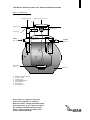
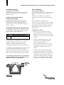
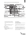
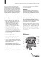
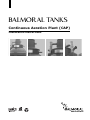
BALMOR AL TANKS
Continuous Aeration Plant (CAP)
Installation instructions
Balmoral Tanks
CONTINUOUS AERATION PLANT (CAP) INSTALLATION INSTRUCTIONS
Figure 1 - CAP diagram
General layout - CAP 6 and CAP 12
Desludging access
Diffuser chamber access
Air vent
Ground level
7
Compressor
Sealed cap
INLET
Ø110mm
6
Water level
5
OUTLET
Ø110mm
3
1
2
4
Fine bubble
diffuser
Settlement chamber
1
2
3
4
5
6
7
Primary settlement tank
Reactor vessel
Transfer pipe
Fine bubble diffuser
Settling pipe
Outlet pipe
Air compressor
This product is subject to warranty
terms and conditions as stated in
Balmoral Tanks’ sewage treatment plant
warranty policy. If you require a copy of
the sewage treatment plant warranty
policy, please contact our After Sales
Team on 01224 859000.
Settlement
1
CONTINUOUS AERATION PLANT (CAP) INSTALLATION INSTRUCTIONS
Installation details
Site installation
Tanks should be set on a smooth level base and
A site is deemed as being “dry” when at no time
Storage before installation
securely tied or propped to prevent overturning,
damage or injury.
Handling and craneage during
transport/installation
The tank should be handled by crane or other
“Dry” ground conditions
does ground water rise above the base of the
tank.
Excavation should allow for a minimum of
150mm space all round and 150mm below the
tank.
suitable equipment using the 50mm lifting eyes
Where difficult ground conditions are
weight of CAP 6 = 230kg. Approximate weight of
clay, etc, an additional depth of 250mm should
provided. Lift only when empty. Approximate
CAP 12 = 330kg.
Superimposed loads/protected areas
No superimposed loads, such as vehicles, should be
allowed within the protective area of the tank as
shown in figure 2 and the table below.
CAP
BCAP6
BCAP12
encountered, ie, in unstable ground or shrinking
be excavated to allow for hardcore and sand
blinding which provides a firm base for the
concrete bed.
Installation procedure
•
Protected areas around tanks
Radius from centre of tank (m)
3.5
4
The tank should not be situated close to a driveway or
carefully onto concrete and check tank is true
and level.
•
before filling outer chamber to the same level.
This prevents excessive pressure on inner
chamber.
If vehicular or other superimposed loads are required
that no loads are transmitted directly onto the tank.
If a reinforced concrete slab is not provided for
vehicle superimposed loads, this may result in
the plant warranty being withdrawn.
Figure 2
Protected areas
depth, place and consolidate additional
Fill inner chamber with water until 50% full
protected area should also be fenced off. (See figure 2)
qualified civil/structural engineer, must be in place so
Fill tank to approximately 450mm water
concrete carefully under tank.
subjected to additional superimposed loads. The
surround or reinforced concrete slab, designed by a
strength 25N/mm2) in base of excavation,
grade and level to within 20mm. Lower tank
roadway, or anywhere there is a risk of it being
to come within the protected area a concrete
Place wet concrete (slump test 30mm,
•
Continue to fill the tank with water whilst
simultaneously backfilling around the tank
with 12-15mm gravel in 150mm thick layers,
ensuring the level of water in the tank is
maintained at approximately 200mm higher
than the level of backfill. This will maintain
equal pressure inside and outside the tank
CONTINUOUS AERATION PLANT (CAP) INSTALLATION INSTRUCTIONS
2
Figure 3
Site installation diagram
Note: Failure to adhere strictly to the written installation instructions will render any warranty null and void.
The diffuser is suspended within the tank for transit. The diffuser must be lowered into position on the base of the tank prior to use.
and will prevent flotation during installation.
Site installation
cover the tank with a 200mm layer of gravel
A site is deemed as “wet” when ground water rises
When the tank is full of water continue to
backfill.
•
“Wet” ground conditions
above the base of the tank.
Finally, complete backfilling up to ground level
Excavation should allow for a minimum of 300mm
required.
tank.
with earth or reinforced ground slab as
space all round the tank and 150mm below the
Gravel specification
Where difficult ground conditions are encountered,
•
Pea gravel or crushed aggregate of uniform
additional excavation should take place, as deemed
•
Chemically inert, washed clean and free of
Backfill material must be:
particle size 12-15mm.
contaminants.
ie, in unstable ground or shrinking clay, etc,
necessary by the supervising engineer, to allow for
hardcore and sand blinding which provides a firm
base for the concrete bed.
3
CONTINUOUS AERATION PLANT (CAP) INSTALLATION INSTRUCTIONS
In poor soil conditions it is essential to make
substantial provision for planking, strutting and
temporary shuttering. Adequate pumps should be
onto the neck of the tank. The tank neck can be
cut on site and adjusted.
provided to keep the excavation free from ground
Ventilation
Provision should also be made for temporary covers
access shaft to allow ventilation of the tank through
water at all times during the course of the work.
and fencing around the excavation site to comply
with statutory health & safety requirements.
Installation procedure
•
Place wet concrete (slump test 30mm, strength
extend to the upper most ridge of the building and
must not terminate at eve height. Flush fitting tile
vents are not recommended.
Electrical power requirements
concrete and check tank is true and level.
3-core steel wired armoured (SWA) cable. Refer to
Fill inner chamber with water until 50% full
before filling outer chamber to the same level.
This prevents excessive pressure on inner
Power requirement is single phase 240V, through a
the product drawings supplied with your unit for
location of the air blower housing unit and specific
power ratings to size the electrical cable.
chamber. Place and consolidate additional
Remove the air blower housing from the turret and
haunch concrete up and around the bottom
connection in the turret. Pull through sufficient slack,
concrete carefully under tank. Thereafter,
•
the soil stack on the source building. This stack must
25N/mm2) in base of excavation, grade and
level to within 20mm. Lower tank carefully onto
•
A 110mm dia uPVC pipe connection is fitted in the
third of of tank circumference.
Continue to fill the tank with water and
carefully place concrete around the tank in
150mm thick layers, ensuring that there are no
voids remaining around the tank, and that the
feed the SWA cable into the tank through the gland
approx 750mm, into the tank and route the cable
through the base of the air blower housing via the
gland connection. Cable slack is required to facilitate
removal of the lid.
level of water inside the tank is maintained at a
level approximately 450mm higher than that of
the concrete backfill.
Figure 4
Inside the air blower turret
•
Do not use a vibrating poker.
•
Continue to fill the tank with water until it
reaches the height of the outlet pipe.
Air blower
•
The neck extension can only be surrounded in
M25 gland
hardened (approx 24 hrs).
Armoured
cable
concrete after the concrete around the tank has
Continue to backfill up to ground level (or fit
reinforced concrete slab) only after concrete around
tank has been allowed to harden for 24 hours.
Manhole cover
The pedestrian duty manhole cover and frame are
manufactured in tough polyethylene and fit directly
Connect switch
to air blower
housing
Exit through
M20 gland
on isolator
switch
Isolator
switch
Armour
cable sleeve
CONTINUOUS AERATION PLANT (CAP) INSTALLATION INSTRUCTIONS
Inside the air blower housing
Remove the four screws securing the top of the air
blower housing to access the internals. The SWA
supply should be wired into the supplied rotary
switch using the gland package supplied. Remove
the plug on the end of the air blower cable (if fitted)
and wire into the output side of the rotary switch
using the gland provided. Secure the switch to the
air blower housing, positioning it next to the air
blower using two screws and close the switch
housing.
The incoming power supply to the tank must be
installed with a separate isolation switch and earth
leakage circuit breaker in the source building.
Ensure the SWA cable is correctly installed earthing
the outer steel armouring at both ends.
Finally, complete backfilling up to ground level with
earth or reinforced ground slab as required.
4
Balmoral Tanks
Head Office & Factories
Balmoral Park, Loirston, Aberdeen AB12 3GY, Scotland
Telephone +44 (0)1224 859000 Fax +44 (0)1224 859123
E-mail [email protected] www.balmoraltanks.com
After Sales
Telephone +44 (0)1224 859100 Fax +44 (0)1224 859123
© 2010 Balmoral Tanks. All rights reserved. This publication is protected by copyright. No part of it may be reproduced, stored in a retrieval system, or transmitted, in any form, by any means, electronic, mechanical, photocopying, recording or
otherwise, without the prior written permission of the copyright owners. Balmoral Tanks believe that the information printed in this brochure is accurate, and published for information only. No warrants, express or implied, are contained therein, nor
does any legal liability attach to Balmoral Tanks for any reason whatsoever. The company’s policy is one of continuous product improvement and we reserve the right to make alterations to our range and specification without prior notice.
TNK-CAPINST-0610-Rev A
BALMOR AL TANKS