1
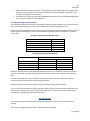
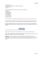
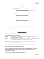
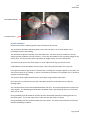
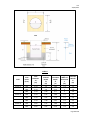
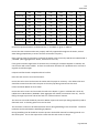
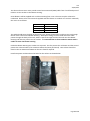
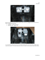
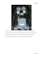
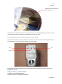
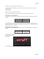
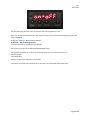
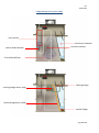
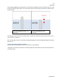
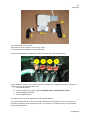
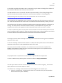
V22 22/08/2014 Vortex Installation Manual The information contained within this Installation Guidance Manual is provided for general information purposes only and does not take into account any specific requirements resulting from your particular location and/or site, of which Water Technology Engineering Limited has no knowledge. Whilst we endeavour to keep the information up to date and correct, we make no representations or warranties of any kind, express or implied, about the completeness, accuracy or reliability of the information contained within the Installation Guidance Manual. Special attention should be paid to the siting of the tank as damage may be caused to the exterior as a result of inappropriate siting. We would advise that due to the wide variety of possible ground conditions, specialist installation advice should be sought from a suitably qualified professional as to the appropriate installation method for your particular location/site. It is the responsibility of whoever is instructed to install the tank, to ensure that the installation method and materials used are suitable for the Tank and specific location/site conditions at all times of the year. Water Technology Engineering Ltd do not accept liability for any loss or damage caused as a result of the customer’s failure to ensure appropriate siting of the tank or of an unsuitable, inappropriate or incorrect installation. Page 1 of 27 V22 22/08/2014 Installation Record Sheet This page must be completed by the installer and retained by the owner. Should the property change hands this sheet must be given to the new owner. WTE Reference This can be found at the top right hand side of the Delivery Note Date of Installation Name of Installer Address of Installer Phone Number of Installer Air Blower Serial Number Larger tanks will have two Air Blowers Air Blower Back Pressure Reading A reading must be recorded for each Air Blower Page 2 of 27 V22 22/08/2014 Health & Safety Sewage poses a serious risk to health. Pathogens in sewage and wastewater can lead to many diseases such as: Campylobacteriosis Hepatitis A Shigellosis Cryptosporidiosis HIV Paratyphoid Fever Escherichia coli Diarrhoea Leptospirosis Typhoid Fever Encephalitis Methaemoglobinaemia Yersiniosis Gastroenteritis Poliomyelitis Giardiasis Salmonellosis Every precaution should be taken to ensure a safe working environment. Introduction The Vortex sewage treatment plant is designed to process wastewater for buildings that do not have access to municipal wastewater infrastructure. The Vortex system provides an ideal solution for domestic homes, offices, pubs, restaurants, campsites and other sites that require on site wastewater treatment. The Vortex tank is made from HDPE and is divided into three chambers with each chamber performing a different step in the treatment process. 1. Wastewater enters the Vibro Screen where any solids are physically broken down by coarse air bubbles. 2. The wastewater then flows into the aeration chamber whaere it is aerated by a fine bubble diffuser. The fine air bubbles provide excelleny oxygen transfer into the wastewater slurry and enable a bacterial culture to develop. These aeraboc bacteria then digest pollutants in the wastewater and clean it. 3. The cleaned wastewater then enters the clarification chamber where settleable and floating solids are allowed to form a sludge at the bottom and top of the chamber. The clean effluent in the middle of the chamber is separated off and allowed to leave the tank. The sludge management system continually recycles the settled and floating sludge for further digestion. WTE Ltd strongly recommends that the Vortex sewage treatment plants are installed by contractors who have been trained on the system’s installation and operation. Please contact our sales office on +44 (0) 1757 289 423 for details of your nearest installer. Assessment Site assessment is required to obtain sufficient information to determine if the site is suitable for a Sewage Treatment Plant and/or drainage field. Pre Installation Checks Is the site in a groundwater protection zone? This may prohibit a drainage field on the site. WTE Ltd or the Environment Agency can provide this information. Page 3 of 27 V22 22/08/2014 Depth of winter groundwater table. The depth of the groundwater table at its highest point during the year is important for both the installation and drainage field if applicable. This must be assessed prior to installation. Percolation tests must be performed to BS6297:2007 and Section H2 of Building Regulations prior to the installation of a drainage field Locating the Sewage Treatment Plant The table below outline the distance that Sewage Treatment Plants should be from various features. This is intended as guidance and clarification should be sought from Building Control. Please note that all Sewage Treatment Plants require servicing and aquatic Sewage Treatment Plants require regular desludging by a tanker and should be located no further than 30m from a vehicle access point Sewage Treatment Plants & Septic Tanks Feature Habitable Building Watercourse Well / Borehole / Spring Site Boundary Road Distance (m) 7 10 50 2 4 Drainage Fields & Drainage Mounds Feature Habitable Building Watercourse Well / Borehole / Spring Site Boundary Distance (m) Building Regulations BS 6297:2007 15 7 10 10 50* 2 Sewage Treatment Plants are designed for pedestrian traffic only. Adequate protection should be given to avoid super- imposed loads. Vehicles must be restricted from the region surrounding the Plant. Vehicles should maintain a distance equal to the depth of the excavation unless the necessary structural protection around the tank has been provided. Suitable fencing to prevent access by children and animals should also be erected. * This is the recommendation of the Environment Agency however WTE Ltd recommends that it be situated at least 200m from a well, borehole or spring as we have known boreholes be rendered unusable with drainage fields located 150m away. Receipt of Goods Upon delivery all goods must be inspected for damage and to ensure that all components are present. Every Vortex sewage treatment plant is supplied with the following: Page 4 of 27 V22 22/08/2014 1x Blower Housing 1x Air Blower (2x Air Blowers on 20PE and 30PE model) 1x Analogue Timer 4x Screws If an Automatic FSR Kit has been ordered there is also an additional: 1x Digital Timer 1x 3 Pin Plug 1x Three Core Cable 1x Solenoid Valve 1x Threaded Tee 1x Threaded Elbow 2x 25mm Pipe Clips 1x 18mm Pipe Clip All of the above items are shipped in the Blower Housing which is placed inside the Vortex tank. If the Vortex tank is damaged or any of the components are damaged or missing then this must be recorded on the P.O.D. (proof of delivery document) and WTE Ltd must be notified immediately. If goods are damaged or items are missing but the P.O.D. has been signed for as undamaged and complete WTE Ltd will be unable to exchange the goods in question or supply additional items free of charge. Handling & Storing The tank should not be lifted if it contains water / wastewater. When lifting the tank both parts of the lid should be in place to prevent the tank distorting. There are two methods of lifting a Vortex sewage treatment plant depending on whether it is an old model without lifting lugs or a new model with lifting lugs. Old Models. The tank should be lifted via a rated strap placed through the inlet and outlet. New Models. The tank should be lifted via a rated strap placed through the lifting lugs. A spreader bar must be used above the tank to prevent the lifting straps from pressing against the lid (see below). Page 5 of 27 V22 22/08/2014 Lifting Straps Spreader Bar The tanks should be stored vertically on a smooth and level surface. Wherever possible the tanks should not be stored on pallets. In warm weather (>15°C) the tanks should be stored in a cool, shaded location if possible. Installation - Below Ground The method of installation is dependant of the site’s ground conditions. Sites are divided into one of three categories: Dry Site Where ground water or the water table does not rise above the base of the excavation at any time of the year. Wet Site Where ground water or the water table rises, or it suspected to rise, above the base of the excavation but not higher than 700mm from ground level. Saturated Site Where ground water or the water table rises, or it suspected to rise, to within 700mm or less of ground level. Do not undertake any concrete work if the temperature is likely to drop below freezing within the following 24 hours. Ensure the area is secure before undertaking any works. Prior to the installation the Transport Screw that prevents the Fine Bubble Diffuser from moving during transportation must be removed. This is to enable the diffuser to be removed for maintenance post installation. Larger Vortex units will have one transport screw per diffuser. Page 6 of 27 V22 22/08/2014 Fine Bubble Diffuser Transport Screw Dry Site Installation Excavate a hole that is 200mm greater than the diameter of the tank. The excavation should be sufficiently deep so that the tank inlet is at the same depth as the incoming drain from the building. The tank must be placed a smooth, level and stable base. This base must be suitable for the site specific ground conditions and soil structure. It must also be suitable for the operating weight of the Vortex tank. The tank must be able to distribute its weight evenly across the whole base. The base must be free of any sharp objects or other objects that may puncture the tank. A 200-300mm reinforced C28/35 concrete base is often the preferred option for many sites If the ground contains high levels of contaminants, including for example sulphate or chloride, this concrete mix will not be suitable. In these circumstances the advice of a qualified civil or structural engineer should be sought. The tank should be safely lowered into the excavation using suitable rated straps. Once the tank is in position the inlet and outlet pipes should be connected to the respective drainage pipes. The void around the tank should be backfilled with soft sand. The sand should be free of stones and sharp objects. The backfilling should be done in 200mm layers and tamped by hand so ensure that there are no voids. During backfilling the lid should be closed to prevent the backfill material from being poured in to the Vortex plant. This is also required to ensure that the tank retains its shape. During backfilling the tank should be filled with clean water. The water level inside the tank should lead the backfilling by 200mm. Page 7 of 27 V22 22/08/2014 Please note that an electric cable is required to pass through the wall of the tank above the waterline. The last 200-300mm of backfilling should be done with top soil. The top soil must be loose and free from stones, clay and sharp objects. The top soil should be laid and tamped in the same way as the sand. Finished ground level should be 50mm below the tank lid. This is to prevent the ingress of surface water into the tank. Ground Level Wet Site Installation If required the site should be dewatered prior to, during and after the installation of the Vortex tank via the use of a side sump or other appropriate dewatering method. During dewatering it is essential that cement and other constituents are not drawn out of the concrete by the action of the dewatering pumps. Depending on site conditions the excavation may require shuttering to prevent it from collapsing. Independent engineering advice should be sought if there is any doubt regarding these issues. Page 8 of 27 V22 22/08/2014 Table A Tank In Ground Depth 'B' (m) Total Length & Concrete Excavation Width of Backfill Depth Excavation ‘C’ ‘E’ ‘L’ (m) (m) (m) Tank Inlet Invert (mm) Tank Diameter 'D' (m) Vortex 4 150 1.34 1.5 1.65 1.8 1.43 650 1.34 2.0 2.15 1.8 1.43 900 1.34 2.25 2.4 1.9 1.43 150 1.44 1.51 1.66 2 1.43 650 1.44 2.01 2.16 2 1.43 900 1.44 2.26 2.41 2 1.43 150 1.66 1.51 1.66 2.1 1.43 650 1.66 2.01 2.16 2.4 1.43 900 1.66 2.26 2.41 2.4 1.43 Vortex 6 Vortex 8 Page 9 of 27 V22 22/08/2014 Vortex 10 Vortex 15 Vortex 20 Vortex 30 150 1.76 1.51 1.66 2.3 1.43 650 1.76 2.01 2.16 2.5 1.43 900 1.76 2.26 2.41 2.6 1.43 203 1.76 2.25 2.4 2.6 2.15 703 1.76 2.75 2.9 2.6 2.15 203 2.05 2.25 2.4 3 2.15 503 2.05 2.55 2.7 3 2.15 203 2.3 2.25 2.4 3.3 2.15 503 2.3 2.55 2.7 3.3 2.15 Excavate a square excavation to the dimension ‘L’ and depth ‘E’ given in Table A. Ensure that the excavation sides are properly and fully supported throughout the works, with all water being pumped away to ensure that the excavation is kept dry. Place concrete onto dry formation to a depth of 150mm using a semi-dry C28/35 mix to BS EN 206-1 / BS 8500. (Max aggregate Size: 40mm, Consistence class: S1) If the ground contains high levels of contaminants, including for example sulphate or chloride, this concrete mix will not be suitable. In these circumstances the advice of a qualified civil or structural engineer should be sought. Compact and finish with a tamped and level surface. Place the tank onto the concrete formation. Ensure the tank is level and connect the outlet and inlet pipes as necessary. The rubber Inlet Seal should be inserted into the inlet hole prior to the inlet pipe being inserted into the tank. Fill the tank with 300mm of clean water. Ensure the tank is secure and surround the tank to the depth ‘C’ given in Table A with a semi-dry C28/35 mix to BS EN 206-1 / BS 8500. (Max aggregate Size: 40mm, Consistence class: S1). Ensure filling is brought up on each side of the tank in a uniform and even manner. The concrete surround should be poured in 200mm layers with each layer being tamped by hand to eliminate voids. A vibrating poker must not be used. The tank must continue to be filled with clean water during backfilling of the excavation. The water inside the tank should lead the backfilling by 300mm. During backfilling the lid should be closed to prevent the backfill material from being poured in to the Vortex plant. This is also required to ensure that the tank retains its shape. Please note that an electric cable is required to pass through the wall of the tank above the waterline. Page 10 of 27 V22 22/08/2014 Finish with a hand tamped level surface. Ensure excavation is kept free from water for at least 3 days (may reduce to 1 day in very warm weather). This is to allow the concrete to set. The water in the tank must remain in place until the concrete has fully cured. Once the concrete has set the excavation should be backfilled with gravel. Filling is to be undertaken uniformly on each side to prevent uneven loading on the tank. The last 300mm should be backfilled with topsoil. Backfilling must terminate 50mm below the lid of the tank. Saturated Site Installation If required the site should be dewatered prior to, during and after the installation of the Vortex tank via the use of a side sump or other appropriate dewatering method. During dewatering it is essential that cement and other constituents are not drawn out of the concrete by the action of the dewatering pumps. Depending on site conditions the excavation may require shuttering to prevent it from collapsing. Independent engineering advice should be sought if there is any doubt regarding these issues. Page 11 of 27 V22 22/08/2014 Table B Tank Inlet Invert (mm) Tank Diameter 'D' (m) Tank In Ground Depth 'B' (m) Vortex 4 150 1.34 1.5 1.65 1.9 1.5 650 1.34 2.0 2.15 2 1.8 900 1.34 2.25 2.4 2 2.0 150 1.44 1.51 1.66 2.1 1.5 650 1.44 2.01 2.16 2.1 2.0 900 1.44 2.26 2.41 2.1 2.2 150 1.66 1.51 1.66 2.4 1.5 650 1.66 2.01 2.16 2.4 2.0 Vortex 6 Vortex 8 Total Length & Concrete Excavation Width of Backfill Depth Excavation ‘C’ ‘E’ ‘L’ (m) (m (m) Page 12 of 27 V22 22/08/2014 Vortex 10 Vortex 15 Vortex 20 Vortex 30 900 1.66 2.26 2.41 2.4 2.2 150 1.76 1.51 1.66 2.5 1.5 650 1.76 2.01 2.16 2.6 1.8 900 1.76 2.26 2.41 2.6 2.2 203 1.76 2.25 2.4 2.6 2.0 703 1.76 2.75 2.9 2.6 2.5 203 2.05 2.25 2.4 3 2.2 503 2.05 2.55 2.7 3 2.5 203 2.3 2.25 2.4 3.3 2.2 503 2.3 2.55 2.7 3.3 2.5 Excavate a square excavation to the dimension ‘L’ and depth ‘E’ given in Table B. Ensure that the excavation sides are properly and fully supported throughout the works, with all water being pumped away to ensure that the excavation is kept dry. Place concrete onto dry formation to a depth of 150mm using a semi-dry C28/35 mix to BS EN 206-1 / BS 8500. (Max aggregate Size: 40mm, Consistence class: S1) If the ground contains high levels of contaminants, including for example sulphate or chloride, this concrete mix will not be suitable. In these circumstances the advice of a qualified civil or structural engineer should be sought. Compact and finish with a tamped and level surface. Place the tank onto the concrete formation. Ensure the tank is level and connect the outlet and inlet pipes as necessary. The rubber Inlet Seal should be inserted into the inlet hole prior to the inlet pipe being inserted into the tank. Fill the tank with 300mm of clean water. Ensure the tank is secure and surround the tank to the depth ‘C’ given in Table B with a semi-dry C28/35 mix to BS EN 206-1 / BS 8500. (Max aggregate Size: 40mm, Consistence class: S1). Ensure filling is brought up on each side of the tank in a uniform and even manner. The concrete surround should be poured in 200mm layers with each layer being tamped by hand to eliminate voids. A vibrating poker must not be used. The tank must continue to be filled with clean water during backfilling of the excavation. The water inside the tank should lead the backfilling by 300mm. During backfilling the lid should be closed to prevent the backfill material from being poured in to the Vortex plant. This is also required to ensure that the tank retains its shape. Page 13 of 27 V22 22/08/2014 Please note that an electric cable is required to pass through the wall of the tank above the waterline. Finish with a hand tamped level surface. Ensure excavation is kept free from water for at least 3 days (may reduce to 1 day in very warm weather). This is to allow the concrete to set. The water in the tank must remain in place until the concrete has fully cured. The remaining excavation should be backfilled with topsoil. Backfilling must terminate 50mm below the lid of the tank. Installation – Above Ground The tank must be placed a smooth, level and stable base. This base must be suitable for the site specific ground conditions and soil structure. It must also be suitable for the operating weight of the Vortex tank. The tank must be able to distribute its weight evenly across the whole base. The base must be free of any sharp objects or other objects that may puncture the tank. A 200-300mm reinforced concrete base is often the preferred option on many sites For sites where the winter temperature may drop below 0°C the Vortex must be insulated against the cold. A possible method of insulating the Vortex is to construct a solid wall, 50mm shorter than height of the tank, around the Vortex unit. There should be a gap of at least 300mm between the tank and the wall and the gap can be filled with compacted sand or other insulative material. Blower Housing Some Vortex units are supplied with the Blower Housing as a separate item. If the Blower Housing has been supplied as a separate item it must be fastened to the fixed part of the tank lid using the screws provided. Ensure that the airlines are able to pass through the holes in the blower housing. Electrical Installation All electrical work must be carried out by qualified personnel, using suitable materials and must comply with current regulations. All electrical items must be sited and installed so that wherever possible a service engineer has full access to the system without requiring entry to a building. Page 14 of 27 V22 22/08/2014 The electrical contractor must provide a steel wire armoured (SWA) cable from a local fused point of isolation to two sockets in the Blower Housing. Some blowers will be supplied with a cable containing four cores. The cores may be coloured or numbered. Please refer to the manual supplied with the blower as to which core is which. Generally the cores are as follows. +ve -ve Earth Alarm (+ve) Brown or 1 Blue or 3 Yellow & Green Black or 2 The cable should enter the body of the Vortex tank, above the waterline, and then pass up through the lid of the tank into the Blower Housing. Waterproof fittings must be used where the cable passes through the body of the tank, where it passes through the lid of the tank into the Blower Housing and where it passes into the sockets. It is essential that air from inside the Vortex tank is unable to enter the blower housing. Inside the Blower Housing two sockets are required. The first powers the air blower and the second powers the solenoid valve (if an Automatic FSR Kit has been purchased). Two sockets should be fitted so that an Automatic FSR Kit can be retro fitted if required. Install two power sockets above the holes for the airlines as shown below. Page 15 of 27 V22 22/08/2014 Both the air blower and solenoid valve require timers; the timer is plugged into the socket and the device is plugged into the timer. Air Blower – Mechanical Timer Solenoid Valve – Digital Timer It is not possible to plug two timers into a standard double socket so for this reason multiple single sockets are required. To accommodate the timers the sockets must be spaced at least 50mm apart. Page 16 of 27 V22 22/08/2014 For larger Vortex units two air blowers are supplied and an additional socket will be needed. The larger air blower supplies air to the fine bubble diffuser and to the FSR via the solenoid valve. The smaller air blower supplies air to the SSR and coarse bubble diffuser via the regulator. It is essential that any hole made in the base of the Blower Housing is made air tight. Page 17 of 27 V22 22/08/2014 Waterproof cable gland into the Vortex body Cable protection should be provided via 6 amp miniature circuit breaker (MCB) protected by residual current detector (RCD), rated 230V, AC and tripping current 0.03 amps. Once commissioned never disconnect the power to the air blower. If an Automatic FSR Kit has been ordered the solenoid valve will need to be wired using the flex and plug supplied. The terminals on the solenoid are shown below. +ve -ve Earth New style tanks will have a digital timer incorporated into the solenoid valve rather than a timer plugged into a socket. Setting the Timer(s) – Automatic FSR Kit Air Blower – Plug In Analogue Timer A mechanical timer is supplied per Air Blower. Page 18 of 27 V22 22/08/2014 All timers must be set to GMT (Greenwich Mean Time). The mechanical timer(s) should be set so that the air blower operates on a continuous cycle of: 30 minutes ON 15 minutes OFF Each pin on the timer represents 15 minutes. If there are two timers they must be set so that they are on and off at the same time. Solenoid Valve – Plug In Digital Timer The digital timer that operates the solenoid valve must be set so that it energises the solenoid as follows: Valve Opens 00:00 hrs 12:00 hrs Valve Closes 00:05 hrs 12:05 hrs The mechanical timer must be set so that is does not deprive the air blower of power when the solenoid valve opens. It is therefore recommended that the Air Blower is active between 23:30 hrs – 00:30 hrs and 11:30 hrs – 12:30 hrs. Solenoid Valve – In Line Digital Timer The digital timer that operates the solenoid valve must be set so that it energises the solenoid as follows: Valve Open 0hrs, 5mins (00:05:00) Valve Closed 11hrs, 55mins (11:55:00) To set the timer press MODE. ON-OFF will be displayed. Press ENTER. Press ENTER three (3) times. Page 19 of 27 V22 22/08/2014 Press ADD five (5) times. Press ENTER three (3) times. Press ADD once (1). Press ENTER. Press ADD once (1). Press ENTER. Press ADD five (5) times. Press ENTER. Press ADD five (5) times. Press ENTER three (3) times. ON-OFF will flash. Page 20 of 27 V22 22/08/2014 The solenoid valve will then open for five minutes counting down to zero. After five minutes the solenoid valve will close for eleven hours, fifty five minutes where upon the cycle is repeated. Setting the Timer(s) – No Automatic FSR Kit Air Blower – Plug In Analogue Timer A mechanical timer is supplied per Air Blower. The timer(s) must be set to GMT (Greenwich Mean Time). The timer(s) should be set so that the air blower operates on a continuous cycle of: 30 minutes ON 15 minutes OFF Each pin on the timer represents 15 minutes. If there are two timers they must be set so that they are on and off at the same time. Page 21 of 27 V22 22/08/2014 Sludge Management System (SMS) Vibro Screen Clarification Chamber Coarse Bubble Diffuser Aeration Chamber Fine Bubble Diffuser Floating Sludge Floating Sludge Return (FSR) Settled Sludge Return (SSR) Settled Sludge Page 22 of 27 V22 22/08/2014 The Floating Sludge Return (FSR) pipe in the Clarification Chamber must be trimmed so that it is able to skim the surface of the water. This can only be done once the tank is full of water. Please see the pictures below. 40-50mm Floating Sludge Return Pipe – As delivered Floating Sludge Return Pipe – Trimmed The FSR pipe must be trimmed as shown above. Ideally this should be done with pipe shears, not a saw, to ensure a clean cut. Once the FSR pipe has been trimmed the Sludge Management System (Sludge Management System) must be set. Vortex Tanks with an Automatic FSR Kit Connect the threaded fittings to the solenoid valve as shown below. The yellow arrow shows the direction of flow through the valve when the valve is open (the valve is normally closed). Page 23 of 27 V22 22/08/2014 A C B A is connected to the air blower. B is connected to the regulator via the large airline. C is connected to the FSR pipe via the small airline. Air from B is supplied to the Regulator inside the Vortex tank. See picture below. 1 2 3 4 The Air Regulator must be set so that the correct volume of air is supplied to all four components inside the Vortex sewage treatment plant: 1. Fine bubble diffuser 2. Floating sludge return (FSR) – This is redundant when a solenoid valve s fitted 3. Settled sludge return (SSR) 4. Coarse bubble diffuser The majority of air must be supplied to the fine bubble diffuser. The coarse bubble diffuser in the Vibro Screen should continuously blow air into the chamber to physically breakdown solids entering the tank. The aeration in the Vibro Screen should resemble vigorously boiling water. Page 24 of 27 V22 22/08/2014 Air should be supplied to the SSR so that it continuously recycles water and sludge from the base of the Clarification Chamber back to the Aeration Chamber. The FSR should have its air turned off. Air is supplied automatically to the FSR pipe when the solenoid valve opens. This enables the FSR to skim floating sludge off the top of the Clarification Chamber and return it to the Aeration chamber for further digestion. A video showing what the aeration in the Vortex should look like can be seen here: http://www.youtube.com/watch?v=SdFbJMEjWrw It is essential that the Air Regulator is set correctly as the system may fail to function correctly if it is not. WTE Ltd recommends that Vortex tanks are installed and commissioned by trained personnel. Vortex Tanks without an Automatic FSR Kit The air blower should be connected directly to the large diameter airline. Air from the blower is supplied to the Air Regulator inside the Vortex tank. See picture below. 1 2 3 4 When the tank is supplied the airline to the FSR is not connected to valve 2. The FSR airline should be cut to length and attached to valve 2. The Air Regulator must be set so that the correct volume of air is supplied to all four components inside the Vortex sewage treatment plant: 5. Fine bubble diffuser 6. Floating sludge return (FSR) 7. Settled sludge return (SSR) 8. Coarse bubble diffuser The majority of air must be supplied to the fine bubble diffuser. The coarse bubble diffuser in the Vibro Screen should continuously blow air into the chamber to physically breakdown solids entering the tank. The aeration in the Vibro Screen should resemble vigorously boiling water. Page 25 of 27 V22 22/08/2014 Air should be supplied to the SSR so that it continuously recycles water and sludge from the base of the Clarification Chamber back to the Aeration Chamber. The FSR should have its air turned off. The FSR is opened manually to skim floating sludge off the top of the Clarification Chamber and return it to the Aeration chamber for further digestion. A video showing what the aeration in the Vortex should look like can be seen here: http://www.youtube.com/watch?v=SdFbJMEjWrw It is essential that the Air Regulator is set correctly as the system may fail to function correctly if it is not. WTE Ltd recommends that Vortex tanks are installed and commissioned by trained personnel. The back pressure in the airline should be checked using a pressure gauge whilst the air blower(s) is running. The back pressure should be 150mbar (0.15bar). If the backpressure is greater than 150mbar then valves on the regulator should be opened to reduce the restriction to air flow. In order to validate any future warranty claim on the air blower a record of the back pressure at the time of installation will be required. Please record the back pressure on the installation record sheet at the front of this manual and inform the owner that the sheet must be retained. Ventilation All Sewage Treatment Plants and Septic Tanks will produce methane and other gasses that must be vented out of the tank. In the case of Sewage Treatment Plants where air is blown into the system there must be sufficient ventilation to allow this air to be expelled from the lid of the tank. The most common method of ventilation is to utilise the soil vent stack on the outside of the building. This provides an open duct for air, methane and other gasses to be expelled from the Sewage Treatment Plant or Septic Tank Pumped Outlet If a pumped outlet is required WTE Ltd can provide a separate Effluent Pump Station. To order an Effluent Pump Station please contact our office on +44 (0) 1759 369 915. Effluent Disposal This will require either a Permit or Permit Exemption from the Environment Agency, Environment Agency Wales, NI Environment Agency or SEPA. The effluent from a Sewage Treatment Plant may be discharged in one of three ways: Direct to a watercourse. The watercourse must run 12 months of the year and provide a dilution ratio of 8:1 (water: effluent). Page 26 of 27 V22 22/08/2014 Below ground drainage field. This must be designed, located and constructed to BS6297:2007 and Section H2 of Building Regulations. Above ground drainage filed. This is a specialist structure. Please contact WTE Ltd. The best disposal method can depend on a variety of site factors including percolation results, soil type, water table level and topography of the site. Please contact WTE Ltd if you have any queries regarding the disposal off effluent as illegal discharges may result in prosecution. Commissioning Providing the installation procedure above has been done correctly there is no need for commissioning. It is not unusual for untrained contractors to make mistakes during the installation process, particularly when setting the Air Regulator. For this reason we strongly recommend that once the tank has been installed it is commissioned by a trained installer or service engineer to ensure that it is ready for use. Please contact our office on +44 (0) 01759 369 915 for details of your nearest trained contractor. We are always looking to expand our network of trained contractors. If you are interested in becoming a WTE approved installer/service engineer please contact our office on the numbers above. Page 27 of 27