1
For the heating engineer
Installation manual
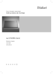
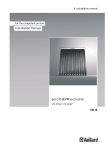
auroTHERM
Multi-row in-roof mounting
VFK 145/2 H/V
VFK 155 H/V
GB
Table of contents
Tabel of contents
1
1.1
1.2
1.3
1.4
Notes on the documentation .............................3
Other applicable documents .................................... 3
Storing documents ..................................................... 3
Symbols used ............................................................... 3
Applicability of the manual ...................................... 3
2
2.1
2.1.1
2.2
2.3
2.4
2.5
2.5.1
2.5.2
2.5.3
2.5.4
2.6
Safety .................................................................. 4
Safety and warning information .............................4
Classification of warnings .........................................4
Intended use ................................................................4
General safety instructions ......................................4
Combination with other components ....................5
Operational conditions ..............................................5
Maximum wind load ...................................................5
Maximum standard snow load .................................5
Roof pitches .................................................................5
Edge distances.............................................................5
CE label .........................................................................5
3
3.1
3.2
3.3
3.4
3.5
3.6
3.7
3.8
Transport and assembly instructions ............. 6
Transport and handling instructions......................6
Installation instructions ............................................6
Technical Guidance .....................................................6
Related documents.....................................................6
Regulations for the prevention of accidents ....... 7
Lightning protection .................................................. 7
Frost protection ........................................................... 7
Overvoltage protection ............................................. 7
4
Interconnection scheme ................................... 8
5
5.1
5.2
5.3
5.4
5.5
5.5.1
5.5.2
5.5.3
5.5.3.1
5.5.3.2
5.5.8
5.6
Assembly ............................................................ 11
Required tools .............................................................11
Preparing the roof duct ...........................................12
Installation kits ...........................................................12
Installation dimensions ............................................17
Installation ...................................................................18
Preparing the roof .....................................................19
Laying out the collectors .........................................19
Fitting the front sections ....................................... 20
Left hand front section .......................................... 20
Remaining front sections (centre and
right hand front sections) ........................................21
Fitting the first vertical collector row..................23
Fitting the remaining vertical collector rows.....27
Fitting the side sections and intermediate
plates .......................................................................... 30
Attaching trapezoidal plates, connectors,
ridge sheets and tile supports...............................32
Re-covering the roof ................................................36
Checklist ......................................................................37
6
6.1
De-commissioning ........................................... 38
Removing the flat collectors ..................................38
5.5.4
5.5.5
5.5.6
5.5.7
2
7
7.1
7.2
7.3
Recycling and disposal .................................... 39
Collectors ....................................................................39
Packaging....................................................................39
Solar fluid ...................................................................39
8
8.1
8.2
Warranty and customer service..................... 39
Vaillant warranty .......................................................39
Vaillant Service..........................................................39
9
Technical Data ..................................................40
Installation manual auroTHERM 0020100606_01
Notes on the documentation 1
1
Notes on the documentation
The following instructions are intended to guide you
throughout the entire documentation.
1.4
Applicability of the manual
These installation manual applies exclusively to flat collectors with the following article numbers:
Collector type
1.1
Article number
Other applicable documents
auroTHERM
When assembling the flat collectors, observe all installation instructions for the parts and components in the
solar system, as well as the material lists for the installation kits. These documents are included with the individual parts of the installation and ancillary components.
We accept no liability for a damage caused by failure
to observe these instructions.
Table 1.1 Collector types and article numbers
1.2
> For the flat collector article number please see the
identification plate on the upper collector edge.
Storing documents
Please pass on this installation manual and all other
applicable documents and auxiliary equipment to the
plant operator, whose responsibility it is to ensure the
manuals and auxiliary equipment are available whenever
required.
1.3
VFK 145/2 H
0010004457, 0010008899
VFK 145/2 V
0010004455, 0010008898
auroTHERM plus
VFK 155 H
0010013174
VFK 155 V
0010013173
Vaillant flat collectors are available in different versions:
A variant for the horizontal collector position (VFK H)
and a variant for the vertical collector position (VFK V).
The instructions apply to multi-row in-roof mounting of
Vaillant flat collectors. In this instance, a collector array
is integrated into the roof.
Symbols used
Please observe the safety instructions in this installation
manual for the installation of the collector.
The collectors are arranged on top of and next to one
another:
– 2 to 12 collectors next to one another,
– 2 or more collectors on top of one another
(depending on roof height).
Furthermore, with the VFK H it is only possible to mount
two collectors on top of one another.
a
Symbol that denotes danger:
– Imminent danger to life
– Risk of severe personal injury
– Risk of slight personal injury
e
b
i
Symbol that denotes danger:
– Risk of death from electric shock
Generally, the installation steps and the instructions
described in this manual are valid for both collector
positions and for all array arrangements.
Any different installation steps are clearly pointed out:
Symbol that denotes danger:
– Risk of material damage
– Risk of damage to the environment
w Only for the horizontal collector position
Symbol that denotes useful tips and
information
s Only for the vertical collector position
>
Symbol for a required task
Installation manual auroTHERM 0020100606_01
Only when two VFK Hs are on top of one
another
3
2 Safety
2
Safety
2.1
2.2
Safety and warning information
> When assembling the flat collector, take account of
the general safety instructions and the warning notes
that appear before all of the actions.
2.1.1
Classification of warnings
The following warning signs and signal words are used
to classify the warning notices in accordance with the
severity of the possible danger.
Warning sign
a
e
a
b
Signal word Explanation
Danger!
Immediate danger to life
or danger of severe personal injury
Danger!
Risk of death from electric shock
Warning!
Risk of slight personal
injury
Caution!
Risk of material or environmental damage
Intended use
The Vaillant auroTHERM flat collectors are built and
designed according to accepted safety rules and regulations.
Nevertheless, there is still a risk of injury or death to the
user or others or of damage to the unit and other property in the event of improper use or use for which it is
not intended.
The unit is not intended for use by persons (including
children) with reduced physical, sensory or mental capabilities, or lack of experience and/or knowledge, unless
they have been given supervision or instruction concerning use of the unit by a person responsible for their
safety.
Children must be supervised to ensure they do not play
with the unit.
Vaillant auroTHERM flat collectors are used for heating
support and for solar hot water generation.
The flat collectors may only be operated with Vaillant
ready-mixed solar fluid. Passing heating water or hot
water directly through the flat collectors is not permitted.
Any other use or extended use is considered to be
improper. The manufacturer/supplier is not liable for any
resulting damage. The user alone bears this risk.
Intended use also includes observance of the installation
manual and all other applicable documents, as well as
adherence to the maintenance and inspection conditions.
2.3
General safety instructions
Table 2.1 Meanings of the warning signs and signal words
> Please note the following before and/or during the
installation:
2.1.2
Structure of warnings
Warning signs are identified by an upper and lower separating line. and are laid out according to the following
basic principle:
a
Signal word!
Type and source of danger.
Explanation of the type and source of danger
> Measures for averting the risk
Avoid risk of death from falls and falling objects
> Observe the national regulations for working at
heights.
> Wear the Vaillant safety belt.
> Cordon off the areas in the fall zone below the working position so that persons cannot be injured by falling objects.
> Identify the working position, e.g. by signs conforming
to the applicable national regulations.
Avoid danger of burning and scalding
When exposed to solar irradiation, the inside of the collectors can reach 200 °C.
> Remove the sun protection film installed at the factory only after the solar energy system has been
started up.
> Do not perform assembly or maintenance work under
direct sunlight.
> Cover the flat collectors before starting work.
> Preferably work during the morning.
4
Installation manual auroTHERM 0020100606_01
Safety 2
Avoid damage caused by incorrect assembly
In order to install flat collectors according to the installation manual, a qualified engineer is required.
> The installation should thus be performed only if a
qualified engineer is available.
> Use the fastening systems provided by Vaillant for the
flat collectors.
> Assemble the flat collectors as described in this manual.
Avoid malfunctioning of the system caused by air
bubbles
> To fill the system, use the filling trolley to avoid air
bubbles.
> Use the manual air vent installed on the collector
field.
> Install the Vaillant solar automatic air vent in the
highest point of the system or insert the automatic
de-aerator in the solar circuit.
> Observe the relevant installation and operating manual.
2.4
Maximum wind load
The flat collectors are suitable for a maximum wind load
of 1.6 kN/m2.
2.5.2
Maximum standard snow load
The flat collectors are suitable for a maximum standard
snow load of 5.0 kN/m2.
2.5.3
Roof pitches
> Only install multi-row flat collectors in-roof if the roof
pitch is between 22° and 75°.
2.5.4
Edge distances
> Maintain a distance of at least 1 metre from the edges
of the roof and the ridge.
> Do not fit the collectors on a roof overhang.
Combination with other components
Vaillant flat collectors should be combined only with
Vaillant components (fixing, connections) and system
components.
The use of other components or system components
shall be considered as improper use. We accept no liability.
2.5
2.5.1
2.6
CE label
The CE label states that the units as described in the
type overview satisfy the basic requirements of the following directives:
– Directive 97/23/EWG of the European Parliament and
Council for harmonization of the laws of the member
states regarding pressure equipment.
Operational conditions
a
b
Danger!
Danger of personal injury and material
damage caused by a collapsing roof!
A roof with insufficient load-bearing capacity
can collapse as a result of the additional loading caused by the flat collectors.
> Before installation, check the maximum
roof load!
> Mount the flat collectors only on roofs with
a sufficient load-carrying capacity.
> If necessary, call a technician.
auroTHERM flat collectors are built according to the state of the art and recognised
safety rules and regulations.
Conformity with the applicable standards
has been demonstrated.
auroTHERM flat collectors have been successfully tested according to the rules and
requirements for the Solar Keymark.
Caution!
Leaks!
With roof pitches < 22° rainwater can collect
on the cover plates and leaks can occur.
> Only install multi-row flat collectors in-roof
if the roof pitch is between 22° and 75°.
Installation manual auroTHERM 0020100606_01
5
3 Transport and assembly instructions
3
3.1
Transport and assembly
instructions
Transport and handling instructions
b
Caution!
Collectors may be damaged by incorrect
storage!
If the flat collector is not stored correctly,
moisture can penetrate and cause damage in
the presence of frost.
> Always store the flat collectors in a dry
place and protected from the elements.
3.3
The system must be installed in accordance with all relevant and applicable national regulations, and must be
installed to suit site conditions.
Observe all national regulations, including:
– Working at Heights Regulations 2005
– Health and Safety at Work Act 1974
– Electricity at Work Regulations 1989
– IEE Wiring Regulations BS 7671
– Lightning protection requirements
– Equipotential bonding of electrical installations.
3.4
> Always transport the flat collector lying flat to ensure
optimum protection.
> The load can be transported to the roof more easily
using a construction site crane or automatic crane. If
this equipment is not available, an inclined hoist can
be used. In either case, it is essential to guide the flat
collector with additional ropes to prevent swinging or
tilting to the side.
> If motorised equipment is not available, pull the flat
collector on to the roof by sliding them up lean-to ladders or scaffolding boards.
3.2
Installation instructions
> Observe the maximum permissible substructure loading and the required distance from the roof edge in
accordance with EN 1991.
> Attach the flat collectors carefully to ensure that the
brackets can safely withstand the tensile loading that
occurs during storms and adverse weather conditions.
> Align the flat collectors to point south if possible.
> Remove the sun protection film on the flat collectors
only after the solar energy system has been started
up.
> For work on the solar circuit, use only hard soldered
joints, gaskets and compression fittings or press fittings that have been approved by the manufacturer
for use in solar circuits and at correspondingly high
temperatures.
> Thermally insulate the pipes in accordance with the
Heating Systems Ordinance (HeizAnlV), making sure
that the thermal insulation is temperature resistant
(175 °C) and UV resistant.
> Fill the solar system only with Vaillant ready-mixed
solar fluid.
6
Technical Guidance
Related documents
The installation of the solar system must be in accordance with the relevant requirements of Health and
Safety Document No. 635 (The Electricity at Work Regulations 1989), BS7671 (IEE Wiring Regulations) and the
Water Supply (Water Fitting) Regulations 1999, or The
Water Bylaws 2000 (Scotland). It should also be in
accordance with the relevant requirements of the Local
Authority, Building Regulations, The Building Regulations
(Scotland), The Building Regulations (Northern Ireland)
and the relevant recommendations of the following British Standards:
BS EN 806: Specification for installations inside buildings conveying water for human consumption.
BS 6700: Services supplying water for domestic use
within buildings and their curtilages.
BS 5449: Forced circulation hot water central heating
systems for domestic premises. Note: only up to 45 kW.
BS 6880: Low temperature hot water heating systems
of output greater than 45 kW.
Part 1 Fundamental and design considerations.
Part 2 Selection of equipment.
Part 3 Installation, commissioning and maintenance.
BS 6114: Expansion vessels using an internal diaphragm
for unvented hot water supply systems.
BS 4814: Specification for: Expansion vessels using an
internal diaphragm, for sealed hot water heating systems.
Unvented hot water systems must comply with building
regulation G section 3.
Installation manual auroTHERM 0020100606_01
Transport and assembly instructions 3
3.5
Regulations for the prevention of accidents
3.6
Lightning protection
When carrying out works such as solar installation work
it is necessary to do so in a safe and workman like manner, taking due care of any aspects of the works that
could result in injuries to person in or about the building
as well as workers, passers by and the general public at
large. To that end these works must conform, but not be
limited to, the current regulations in force such as the
following
Health and Safety at Work act 1974
Work at Height Regulations 2005
Electricity at Work Regulations 1989
All necessary Building Regulations.
b
Work should be preceded by a risk assessment covering
all aspects of health and safety risks, or training requirements that can reasonably be foreseen to be associated
with the work. All scaffolding in the UK, other than prefabricated (zip-up) scaffold towers, must be designed
and constructed by a vetted contractor, and have suitable kick boards, hand rails and where appropriate netting. Areas around the scaffolding should be zoned off
and marked with suitable warning signs to a suitable distance to protect persons from falling objects.
Workers should have available and use personal protective equipment as necessary. This would include equipment such as fall protection systems, safety gloves, goggles, dust masks as well as any specialised equipment
that may be in use such as lifting and handling equipment.
The completed works shall comply with all necessary
BS EN Standards and Codes of practice as well as Building control or planning requirements and be confirmed
where necessary by notification to building control or
the appropriate competence based notification body.
b
> When fitting the collectors, observe the applicable
national regulations for working at the particular
height.
> Provide the mandatory fall protection by using, e.g.,
roof restraining frameworks or roof protection walls.
> If a roof restraining framework or a roof protection
wall is not appropriate, use safety harnesses such as,
e.g., the Vaillant safety belt (not available in all countries) as fall protection.
> Use gloves to prevent injuries on sharp-edged parts.
> Only use tools and aids (e.g. lifting gear or lean-to ladders) that conform to the particular applicable accident prevention regulations.
3.7
3.8
Caution!
Damage from lightning!
With installation heights of over 20 m, or if
the flat collectors project beyond the ridge of
the roof, the system can be damaged by lightning strikes.
> Connect the electrically conducting parts
to a lightning protection device.
Frost protection
Caution!
Damage due to frost!
Residual water can damage the flat collectors
in frosty weather.
> Never fill or flush the flat collector with
water.
> Only fill and flush the flat collector with
Vaillant ready-mixed solar fluid.
> Check the solar fluid regularly with an antifreeze tester.
Overvoltage protection
a
Danger!
Risk of death caused by improper
installation!
Mains voltage may be present on the pipework as a result of improper installation or
a defective power cable, and can cause personal injury.
> Fasten earthing clamps to the pipework.
> Bond the earthing clamps to a busbar using
16 mm2 copper cable.
b
Caution!
Risk of voltage surge!
Overvoltage can damage the solar system.
> Earth the solar circuit to provide equipotential bonding and overvoltage protection.
> Fasten earthing clamps to the solar circuit
pipework.
> Bond the earthing clamps to a busbar using
16 mm2 copper cable.
> Cordon off the areas in the fall zone below the assembly position so that persons cannot be injured by falling objects.
> Identify the work area with, e.g. signs conforming to
the applicable regulations.
Installation manual auroTHERM 0020100606_01
7
4 Interconnection scheme
4
Interconnection scheme
i
Observe the planning information when
dimensioning the flow rate for the array.
> Connect up the flat collectors using the following
rules:
1
2
3
4
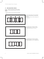
You can connect the flat collectors hydraulically in four different ways, as shown in the
illustration.
However the direction of flow is always from
bottom to top.
Fig. 4.1 Direction of flow
If you connect 1 to 5 collectors one after
another, the hydraulic connections can be
laid one below the other on one side.
1
...
4
5
Fig. 4.2 Series connection of 1 - 5 flat connectors
If you connect 6 to 12 collectors one after
another, the hydraulic connections must be
arranged diagonally, to force a complete flow.
max. 12
1
2
...
11
12
Fig. 4.3 Series connection of 6 - 12 flat connectors
8
Installation manual auroTHERM 0020100606_01
Interconnection scheme 4
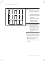
> 12
1
2
...
6
7
8
9
...
13
14
Always connect the individual rows or the
complete collector array hydraulically in parallel one above the other.
> Connect as many flat collectors in series
as possible, but never more than 12.
> Only connect collector rows with the same
aperture area in parallel, to prevent differing pressure losses in the partial collector
arrays.
> Make sure that each partial collector array
has the same total pipe length in the flow
and return lines (Tichelmann System), to
prevent differing pressure losses in the
connecting pipes.
Fig. 4.4 Parallel interconnection (shown here: VFK 145/2V / 155V)
Installation manual auroTHERM 0020100606_01
9
4 Interconnection scheme
1
2
...
5
6
7
8
...
11
12
13
14
...
17
18
Fig. 4.5 Sizes of the individual rows (shown here: VFK 145/2V / 155V)
b
Caution!
Danger of air bubbles if venting
is inadequate!
With 3 or more collector rows connected in parallel, the following
applies: If you do not provide extra
bleeding of the individual rows
during start-up, air bubbles can
occur. To bleed the individual rows,
additional stop valves are required.
> Install a stop valve in the collector flow line ("hot side") of each
individual row.
> Use only stop valves that have
been approved for installation in
solar heating systems.
> Bleed the collector array
according to the following
instructions.
b
Caution!
Danger of material damage as a
result of incorrect fitting!
If the stop valve is closed or incorrectly installed, the flat collector
can be damaged by overpressure.
> Never fit the stop valve in the
collector return line.
> Make sure that the stop valves
are open while the system is
operating.
The flat collector rows that are connected in
parallel must be flushed and bled separately.
> To this end, open each stop valve in turn a
little at a time while the others remain
closed.
> Open all the stop valves after you have
flushed and bled all the rows.
> Then flush and bleed all the collector
arrays together. Only in this way can it be
ensured that no air remains in the collector arrays.
10
Installation manual auroTHERM 0020100606_01
Assembly 5
5
Assembly
This chapter describes the assembly of a multi-row flat
collector array which is integrated into a pitched roof.
i
The assembly of the collectors is always carried out in vertical rows. The hydraulic connections are then attached to the horizontal
rows.
> Before installing the flat collectors in the pitched roof,
carry out the steps shown in Chapters 5.1 to 5.5.
> Then fit the flat collectors into the roof, as described
in Chapter 5.6.
> Before and during the installation, observe the safety
instructions listed in Chapter 2, and also the transport
and assembly instructions listed in Chapter 3.
> Connect the flat collectors according to the interconnection diagram in Chapter 4.
b
Caution!
Roof construction damage due to missing
rear roof ventilation!
Inadequate ventilation can result in mould
growth.
> Ensure that the specified roof ventilation is
present beneath the collectors.
b
Caution!
Danger of damaging internal components!
The interior of the collector is vented by the
opening integrated in the pipe penetration.
> Keep the vent opening clear for troublefree operation.
b
Caution!
Danger of leaks caused by cutting the
cover plates!
Alterations to, or cutting of the supplied cover
plates will result in leaks and invalidation of
the guarantee.
> Do not damage the supplied cover plates in
any way by cutting them, bending them or
similar.
5.1
Required tools
a
Danger!
Danger of personal injury and material
damage!
On roofs made of metals more noble than aluminium (e.g. copper roofs) contact corrosion
can occur at the anchors. Collectors can fall
down and endanger persons.
> Use suitable pads to keep the metals apart.
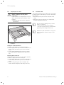
> Have the following tools and materials ready for the
installation of the flat collectors:
Fig. 5.1 Required tools
Installation manual auroTHERM 0020100606_01
–
–
–
–
–
–
–
–
–
Spirit level,
Power screwdriver,
Torx bit,
Drill bit 4.5 mm,
Hammer,
Tape measure/folding ruler,
Rubber hammer,
Utility knife,
Weatherproof silicone and riveting pliers.
11
5 Assembly
5.2
Preparing the roof duct
b
Caution!
Danger of damage caused by water
penetration!
If the roof duct is not implemented correctly,
water can penetrate into the interior of the
building.
> Make sure that the roof duct is properly
implemented.
5.3
Installation kits
The following illustrations show which parts you require
for multi-row in-roof mounting of vertical or horizontal
flat collectors.
> Have the required parts from the installation kits
ready.
> Check the respective deliveries for completeness
using the supplied material lists.
i
The collectors are arranged on top of and
next to one another:
- 2 to 12 collectors next to one another,
- 2 or more collectors on top of one another
(depending on the height of the roof).
i
Furthermore, with the VFK H it is only possible to mount two collectors on top of one
another.
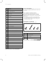
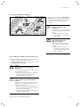
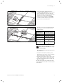
Fig. 5.2 Passing a pipe through the sarking membrane or
roofing felt
Cutting the sarking membrane
> Make a v-shaped cut in the sarking membrane.
> Fold the upper, wider flap on to the roof batten above,
and the lower, narrower flap on to the roof batten
below.
> Fix the sarking membrane tight to the roof batten.
This ensures that the dampness flows away to the
side.
Preparing board-clad roofs
> With board-clad roofs, cut out a hole with a padsaw.
> Make a v-shaped cut in the roofing felt.
> Fold the upper, wider flap on to the roof batten above,
and the lower, narrower flap on to the roof batten
below.
> Fix the roofing felt tight to the roof batten. This
ensures that the dampness flows away to the side.
12
Installation manual auroTHERM 0020100606_01
Assembly 5
2
3
4
5
6
1
13
10
14
11
18
12
19
17
15
22
16
26
20
24
21
27
23
31
28
25
30
33
29
34
32
35
13
Fig. 5.3 Installation kit for vertical collector (VFK 145/2/155 V)
Installation manual auroTHERM 0020100606_01
13
5 Assembly
Item
Description
1
Collector
2
Upper supply (with probe)
3
Return (inlet)
4
Plug (with vent)
5
Clip
6
Pipe coupling
10
Centre ridge plate
11
Upper ridge plate coupling
12
Tile support
13
Additional roof batten
14
Left ridge plate
15
Right ridge plate
16
Lower ridge plate coupling
17
Flexible easyform apron
(can be ordered as option)
18
Support board
19
Left hand horizontal intermediate plate
20
Right hand horizontal intermediate plate
21
Centre horizontal intermediate plate
22
Upper left shorter side section
23
Upper right shorter side section
24
Lower left longer side section
25
Lower right longer side section
26
Spacer
27
Trapezoidal plate
28
Vertical intermediate plate
29
Clamp
30
Screw kits (Nos. 1-4)
31
Bracket
32
End cap
33
Left hand front section
34
Centre front section
35
Right hand front section
Collector array packaging
You require one hydraulic installation set for each collector row and one hydraulic expansion set for each collector per row.
Note on additional roof battens (Item 13)
The installation kit contains additional roof battens.
However, the additional battens that you use during
installation must be neither thicker nor thinner than the
existing ones.
> If the additional roof battens in the installation kit
have differing dimensions from the existing roof battens, battens that are identical to the existing ones
should be provided locally.
Screw kits (Nos. 1 - 4) (Item 30)
The screw kits contain the following screws:
4
3
2
1
Fig. 5.4 Material supplied in screw kits
Screw No.
1
4.5 x 25 mm
2
5 x 30 mm
3
5 x 70 mm
4
M5 x 25/A2
Used with ¬ item number in Table 5.1
11, 10, 14, 15, 33, 34, 35
31, 26, 29, 16, 18
13
11
Table 5.2 Screw usage
Table 5.1 Kit for vertical collector (VFK 145/2/155 V)
14
Installation manual auroTHERM 0020100606_01
Assembly 5
2
4
5
3
6
7
1
13
14
12
17
10
18
11
29
22
27
15
16
23
28
36
19
20
24
32
21
26
13
31
33
25
30
34
35
Fig. 5.5 Installation kit for horizontal collector
(VFK 145/2/155 H)
Installation manual auroTHERM 0020100606_01
15
5 Assembly
Item
Description
1
Collector
2
Upper supply (with probe)
3
Return (inlet)
4
Plug (with vent)
5
Clip
6
7
Pipe coupling
(Not for "two VFK Hs on top of one another")
O-ring pipe coupling
(Only for "two VFK Hs on top of one another")
10
Centre ridge plate
11
Upper ridge plate coupling
12
Tile support
13
Additional roof batten
14
Left ridge plate
15
Right ridge plate
16
Lower ridge plate coupling
17
Flexible easyform apron (can be ordered as option)
18
Support board
19
20
Left hand horizontal intermediate plate
(only for multi-row)
Right hand horizontal intermediate plate
(only for multi-row)
Collector array packaging
You require one hydraulic installation set for each collector row and one hydraulic expansion set for each collector per row.
Note on additional roof battens (Item 13)
The installation kit contains additional roof battens.
However, the additional battens that you use during
installation must be neither thicker nor thinner than the
existing ones.
> If the additional roof battens in the installation kit
have differing dimensions from the existing roof battens, battens that are identical to the existing ones
should be provided locally.
Screw kits (Nos. 1 - 4) (Item 30)
The screw kits contain the following screws:
4
3
2
1
Fig. 5.6 Material supplied in screw kits
21
Centre horizontal intermediate plate (only for multi-row)
22
Upper left shorter side section
23
Upper right shorter side section
24
Lower left longer side section
2
5 x 30 mm
31, 26, 29, 16, 18
25
Lower right longer side section
3
5 x 70 mm
13
26
Spacer
11
27
Trapezoidal plate
4
M5 x 25/A2
28
Vertical intermediate plate
29
Clamp
30
Screw kits (Nos. 1-4)
31
Bracket
32
End cap
33
Left hand front section
34
Centre front section
35
Right hand front section
36
Horizontal intermediate plate (only for single row)
Screw No.
1
4.5 x 25 mm
Used with ¬ item number in Table 5.3
11, 10, 14, 15, 33, 34, 35
Table 5.4 Screw usage
Table 5.3 Kit for horizontal collector (VFK 145/2/155 H)
16
Installation manual auroTHERM 0020100606_01
Assembly 5
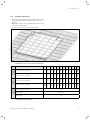
5.4
Installation dimensions
C
> Before installing the flat collectors, make sure you are
clear about the installation dimensions of the collector array.
> Maintain a distance of at least 1 metre from the edges
of the roof and the ridge.
> Do not fit the collectors on a roof overhang.
B
C
E
D
A
C
25800
12226
13570
14880
16190
21530
23590
25650
15960
23700
12
19460
14700
21590
11
10960
13440
19480
10
17400
12170
17370
9
9650
10910
15260
8
15340
9650
13160
8390
7
8390
7120
5860
4600
6
13270
7030
11210
Width of collector array (B)
5
11050
5720
9150
Height of collector array (A)
4
8940
4412
7080
3330
Width of collector array (B)
3
6830
3110
4720
2
Height of collector array (A)
Additional working area (C)
Both
collector
positions
1
5020
Horizontal
collector
position
Vertical
collector
position
Number of collectors
2960
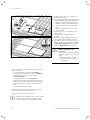
Fig. 5.7 Dimensions for the installation area and the position of the lower roof batten
(the reference line in each case is the roof tile border)
500
Distance (D)
270 - 320
Distance (E)
150
Table 5.5 Dimensions for the installation area and the position
of the bottom roof batten in mm
Installation manual auroTHERM 0020100606_01
17
5 Assembly
The entire installation area consists of the dimensions
for the collector array (A) and (B) and also the additional exposed area (C).
i
5.5
The additional exposed area (C) is needed in
order to be able to carry out the installation
work. After assembly the additional exposed
area (C) is covered up again.
Installation
Multi-row in-roof mounting of Vaillant flat collectors is
always carried out in vertical rows. The flat collectors
have a horizontal orientation (VFK H) or a vertical orientation (VFK V). They are arranged on top of one another
and next to one another in a collector array:
– 2 to 12 collectors next to one another
– 2 or more collectors on top of one another
(depending on roof height)
Furthermore, with the VFK H it is only possible to mount
two collectors on top of one another.
Generally, the installation steps and the instructions
described in this manual are valid for both collector
positions and for all array arrangements.
Any different installation steps are clearly pointed out:
w Only for the horizontal collector position
s Only for the vertical collector position
Only when two VFK Hs are on top of one
another
18
Installation manual auroTHERM 0020100606_01
Assembly 5
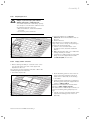
Preparing the roof
A
D
a
Danger!
Danger of personal injury and material
damage caused by a collapsing roof!
A roof with insufficient load-bearing capacity
can collapse as a result of the additional loading caused by the flat collectors.
> Before installation, check the maximum
roof load!
> If necessary, call a technician.
E
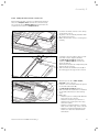
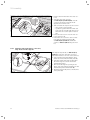
5.5.1
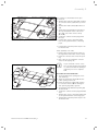
Fig. 5.8 Exposing the installation area and fitting the lower roof batten
5.5.2
> Using the dimensions (¬ Fig. 5.7,
Table 5.5) define the installation area on
the roof.
> Remove the tiles.
There must be a roof batten at the lower
edge of the collector array corresponding to
distances D and E in Table 5.5.
> If there is no roof batten at the corresponding position, attach an additional
batten.
> Make sure that the ends of roof batten are
resting centrally on a rafter.
> Screw the roof batten firmly to each rafter
using one of the supplied No. 3 screws
(¬ Table 5.2/5.4) in each case.
Laying out the collectors
> Before starting assembly of a vertical row of collectors, lay out all the collectors of the upper rows
unpacked on the roof.
The collectors for the lowermost row (this is where the
assembly begins!) are fitted first.
> Follow the steps below:
1
Fig. 5.9 Laying out the collectors
Installation manual auroTHERM 0020100606_01
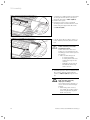
> At the mounting point for each of the collectors above the lowermost row, fix an
additional roof batten (1) to the existing
roof batten.
> Firmly screw the additional roof batten at
two fixing points using the supplied No. 3
screws (¬ Table 5.2/5.4).
Additional roof battens are included in the
delivery (¬ Table 5.1/5.3, Item 13).
The additional roof battens (1) secure the collectors from falling during temporary storage.
> Lay the collectors one after another at the
respective mounting points on the roof
batten (1).
19
5 Assembly
5.5.3
Fitting the front sections
> Fit the front sections in each case at the start of a
vertical collector row.
> Keep exactly to the sequence described here when
doing so.
w
s
For the horizontal collector position you will
require two front sections for each vertical
row.
For the vertical collector position you will
require one front section for each vertical row.
a
Caution!
Leaks caused by inaccurate mounting
position!
Leaks can occur in the collector system if the
framework parts are not assembled precisely.
> Make sure that the fold on the front section rests flush on the roof batten.
> With the help of a spirit level, make sure
that the front section is resting horizontally
on the roof batten.
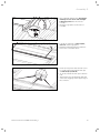
5.5.3.1 Left hand front section
1
Fig. 5.10 Attaching the left hand front section at the bottom
> Pick up the left hand front section
(¬ Table 5.1/5.3, Item 33).
> Fit the left hand front section of the frame
to the 2nd roof batten viewed from below.
The front section will thus rest on the lowest roof batten (the previously fitted additional roof batten).
> Leave the protective film on the adhesive
surface of the flexible apron.
> Let the flexible apron rest on the roof tiles
and push the left hand edge of the apron
between the tiles.
> Screw the front section to the roof batten
with 6 No. 1 screws (¬ Table 5.2/5.4)
using the Torx bit, as shown in (1).
s Only for the vertical collector position
> Continue with the assembly of the vertical collector
row.
w Only for the horizontal collector position
> First attach the second front section as described in
the following.
20
Installation manual auroTHERM 0020100606_01
Assembly 5
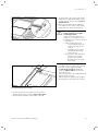
5.5.3.2 Remaining front sections (centre and right
hand front sections)
> Always use a centre front section, up to and including
the last but one vertical collector row
(¬ Table 5.1/5.3, Item 34):
– For all VFK 145/2/155 V, 1 centre front section is
required.
– For all VFK 145/2/155 H, 2 centre front sections are
required.
> Complete the row of front sections with a right hand
front section (¬ Table 5.1/5.3, Item 35).
> Proceed for all the other front sections as described
in the following using the second (centre) front section as an example:
Installation manual auroTHERM 0020100606_01
21
5 Assembly
> Have the centre (or right hand) front section (¬ Table 5.1/5.3, Item 34) of the
frame ready.
> Bend the flexible apron of the previously
fitted front section down by approx. 3 cm
on its right hand side (1).
> Lift the upper protective film on the bent
flexible apron at the top as far as the
bend (1).
> Stick the right hand sheet to the bent over
apron of the left hand sheet (1).
> Take care that the edge of the sheet and
the apron close flush with one another.
> Push the slot on the left hand sheet into
the fold on the right hand sheet (2) and
(3).
> Align the right hand sheet to the mark on
the left hand sheet (4).
> Now remove the entire upper protective
film from the adhesive surface on the left
hand sheet.
> Then press once more on the right hand
sheet.
> Screw the sheet to the roof batten (5)
with 6 No. 1 screws (¬ Table 5.2/5.4)
using the Torx bit.
1
2
3
5
4
Fig. 5.11 Fitting a further front section (here, a right hand or centre front
section)
s Only for the vertical collector position
> Continue with the assembly of the vertical collector
rows after fitting a front section for each one. The
remaining front sections are fitted when starting each
additional vertical row.
w Only for the horizontal collector position
> Continue with the assembly of the vertical collector
rows after fitting two front sections for each row. Further front sections are fitted when starting each additional vertical row.
22
Installation manual auroTHERM 0020100606_01
Assembly 5
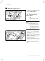
5.5.4
Fitting the first vertical collector row
Before fitting the first collector, you must have prepared
the roof (¬ Chapter 5.5.1), laid out the collectors ready
for a vertical row (¬ Chapter 5.5.2) and have fitted the
required front sections (¬ Chapter 5.5.3).
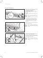
> Hook the left hand collector to the straps
on the front section.
> Align the collector laterally with the mark
(1) on the front section.
> Make sure that the collector is sitting horizontally.
1
Fig. 5.12 Inserting the left hand collector
2
> Screw the collector firmly to the roof battens with 2 of the supplied brackets
(¬ Table 5.1/5.3, Item 31) and No. 2
screws (¬ Table 5.2/5.4) on each side
using the Torx bit.
The folded side (1) of the clamp must point
away from the collector.
> Take care that the chamfered side (2) of
the clamp grips the edge of the collector.
1
Fig. 5.13 Screwing the flat collectors
1
2
Fig. 5.14 Positioning the spacer and roof batten
Installation manual auroTHERM 0020100606_01
> Attach a spacer (1) (¬ Table 5.1/5.3,
Item 26) to the collector.
> If there is no roof batten under the spacer,
fit an additional batten (2)
(¬ Table 5.1/5.3, Item 13) under it.
> Take care that the additional roof batten is
of the same dimensions as the existing
ones.
> Make sure:
– that the spacer is resting flush with the
inner edge of the collector,
– that the roof batten is positioned so
that the holes in the spacer are lying
above the batten,
– that the roof batten under it is resting
flush on the outer edge of the collector,
– that the roof batten terminates in the
middle of a rafter and abuts with the
next batten.
23
5 Assembly
> Screw the roof batten firmly to the rafters
at the right and left next to the spacer
using No. 3 screws (¬ Table 5.2/5.4).
> Remove the spacer.
> Keep the position of the roof batten
unchanged and screw the batten to each
rafter using the supplied No. 3 screws
(¬ Table 5.2/5.4).
Fig. 5.15 Screwing the roof batten
1
> Lay the spacer (1) once more on the collector and the previously fitted roof batten.
b
Fig. 5.16 Screwing the spacer
Caution!
Leaks caused by inaccurate
mounting position!
Leaks can occur in the cover
plates for roof integration if the
mounting position of the spacer is
not precise.
> Take care that the spacer
- is lying horizontally,
- is resting flush at the side
on the inner edge of the
collector,
- terminates at the ends in
line with the inner edge
of the collector.
> Screw the spacer to the roof batten above
the collector with the supplied No. 2
screws (¬ Table 5.2/5.4) using the Torx
bit.
a
24
Danger!
Risk of death caused by
improper assembly!
If not fixed properly, the flat collector can fall off and endanger
persons.
> After fixing each collector,
check that all screwed connections are tight and retighten
them if necessary.
Installation manual auroTHERM 0020100606_01
Assembly 5
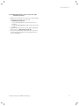
> To fit the next collector, first remove the
additional roof batten with which you previously secured the collector(¬ Fig. 5.9,
Chapter 5.5.2).
> Once you have removed the additional
roof batten, let the collector slide down
slowly until it is resting on the spacer.
b
Fig. 5.17 Fitting the next collector
2
1
Caution!
Leaks caused by inaccurate
mounting position!
Leaks can occur in the cover
plates for roof integration if the
mounting position of the collectors
is not precise.
> Take care that the spacer
- is resting flush at the side
on the inner edge of the
collector,
- terminates at the ends in
line with the inner edge
of the collector.
> Using a spirit level, make sure
- that the collectors line
up above one another,
- that the collector is lying
horizontally.
> Screw the collector firmly to the roof battens with 2 of the supplied brackets
(¬ Table 5.1/5.3, Item 31) and No. 2
screws (¬ Table 5.2/5.4) on each side
using the Torx bit.
The folded side (1) of the clamp must point
away from the collector.
> Take care that the chamfered side (2) of
the clamp grips the edge of the collector.
Fig. 5.18 Screwing the flat collectors
> Fit the collectors for the entire vertical row in the
manner previously described (¬ Figs. 5.12 to 5.18).
> Then make the hydraulic connections as follows.
Installation manual auroTHERM 0020100606_01
25
5 Assembly
Only when two VFK Hs are on top of one
another
> Connect the collectors with the O-ring pipe
coupling (¬ Table 5.3, Item 7).
> Fix the connection with the clips.
A
a
b
Caution!
Danger of damage to the
collectors!
The flat collector can be damaged
if the pipe coupler is not fitted correctly.
> Make sure that the clip (A)
slides into the slot in the O-ring
pipe coupler (B).
a
Danger!
Risk of death caused by
improper assembly!
If not fixed properly, the flat collector can fall off and endanger
persons.
> After fixing each collector,
check that all screwed connections are tight and retighten
them if necessary.
B
Fig. 5.19 Hydraulic connection (2 VFK H on top of one another)
1
3
4
2
Fig. 5.20 Hydraulic connections for the VFK 145/2/155
26
> Connect the flow line (outlet with opening
for collector sensor, ¬ Table 5.3, Item 2)
at the top (1).
> Insert the collector sensor into the opening provided in the flow line.
> Connect the return line (inlet, ¬ Table 5.3,
Item 3) at the bottom (2).
> Fit the 2 plugs (¬ Table 5.3, Item 4) with
the bleed openings (3 and 4) on the opposite side of each collector.
> Secure the connections and plugs with the
clips (¬ Table 5.3, Item 5).
> Connect the collector flow and return lines
to the system with the connecting pipes.
> If necessary check the connections for
leaks.
Installation manual auroTHERM 0020100606_01
Assembly 5
For all other arrangements (VFK H/V)
A
1
a
B
3
2
> Insert the pipe couplers (¬ Table 5.1/5.3,
Item 6) into the side openings in the collector until the end stops are reached (1).
> Secure the pipe couplings with the
clips (2).
b
Caution!
Danger of damage to the
collectors!
The flat collector can be damaged
if the pipe coupler is not fitted correctly.
> Make sure that the clip (A)
slides into the slot in the pipe
coupler (B).
a
Danger!
Risk of death caused by
improper assembly!
If not fixed properly, the flat collector can fall off and endanger
persons.
> After fixing each collector,
check that all screwed connections are tight and retighten
them if necessary.
Fig. 5.21 Hydraulic connection
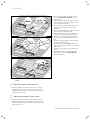
5.5.5
Fitting the remaining vertical collector rows
> Before assembling the next vertical row, lay down the
collectors as described in Chapter 5.6.2.
> Fit the required front section in front of the collectors
(¬ Chapter 5.5.3, Fig. 5.10).
a
Danger!
Risk of death caused by improper
assembly!
If not fixed properly, the flat collector can fall
off and endanger persons.
> After fixing each collector, check that all
screwed connections are tight and
retighten them if necessary.
b
Caution!
Leaks caused by inaccurate mounting
position!
Leaks can occur in the cover plates for roof
integration if the mounting position of the
collectors is not precise.
> Using a spirit level, make sure that the collectors are sitting horizontally and are resting flush with one another.
> Make sure that the distance between the
collectors is 30 +/- 1 mm.
Installation manual auroTHERM 0020100606_01
27
5 Assembly
3
1
2
4
A
a
B
4
Fig. 5.22 Inserting the next collector
> Hook the next collector to the straps of
the front section (1).
> Slide the collector left to the neighbouring
collector (2). Make sure when doing this
– that the collector being fitted slides
under the clamps on the neighbouring
collector to the left as far as the end
stop.
– that pipe couplings slip and fit in the
side openings.
> Align the collector to the marks on the
front sections.
> Secure the pipe couplings with the
clips (3).
> Check the distance between adjacent collectors (4). It must be 30 mm (± 1 mm).
> Fasten the collector at the side to the roof
battens with 2 each of the supplied clamps
(¬ Table 5.1/5.3, Item 29) and the No. 2
screws (¬ Table 5.2/5.4) (cf. Fig. 5.12).
b
Caution!
Danger of damage to the
collectors!
The flat collector can be damaged
if the pipe coupler is not fitted correctly.
> Make sure that the clip (A)
slides into the slot in the pipe
coupler (B).
> Then continue the assembly as for the first vertical
row of collectors:
– Screw down the flat collectors (¬ Fig. 5.13).
– Position the spacer and roof batten (¬ Fig. 5.14).
– Screw the spacer and roof batten down
(¬ Figs. 5.15, 5.16).
– Position the next collector (¬ Fig. 5.17).
When doing this, take care that the left hand side
of the collector slides under the brackets on the
neighbouring collector until it reaches the end
stop.
– Screw the flat collector down.
> Complete the collector row and the entire collector
array in the manner already described.
> Then make the hydraulic connections.
i
28
Whereas the assembly of the collectors takes
place in vertical rows, the hydraulic connections are always made in horizontal rows.
Installation manual auroTHERM 0020100606_01
Assembly 5
1
4
2
3
Fig. 5.23 Fitting the hydraulic connections (1-5 collectors)
Procedure for a horizontal row of up to
5 collectors.
> Connect the flow line (outlet with opening
for collector sensor) (1) at the top on one
side.
> Connect the return (inlet) (2) at the bottom.
> Fit the two plugs with bleed openings at
the top and bottom of the collector on
the other side of the collector array
(3 and 4).
> Secure the connections and plugs with
the clips.
> Connect the collector flow and return
lines to the system with the connecting
pipes.
> Perform the previously listed steps for all
horizontal rows.
After assembly of all rows:
> Remove the red plug from the outlet on
the uppermost row of the collector array.
> Insert the collector sensor into the opening.
> Use a cable tie to prevent the collector
sensor from slipping out.
4
3
Fig. 5.24 Fitting the hydraulic connections (6-12 collectors)
Installation manual auroTHERM 0020100606_01
1
2
i
If you connect 6 or more collectors one after another, the hydraulic connections must be arranged
diagonally, to force a complete
flow.
Procedure for a horizontal row:
> Fit a plug with bleed opening (1) on one
side at the top.
> Insert the return line (inlet) (2) into the
lower opening at the side.
> Insert the flow line (outlet with opening
for collector sensor) (4) into the upper
side opening diagonally opposite.
> Fit a further plug with bleed opening (3)
at the bottom.
> Secure the connections and plugs with the
clips.
> Connect the collector flow and return lines
to the system with the connecting pipes.
> Perform the previously listed steps for all
horizontal rows.
29
5 Assembly
After assembly of all rows:
> Remove the red plug from the outlet on the uppermost row of the collector array.
> Insert the collector sensor into the opening.
> Use a cable tie to prevent the collector sensor from
slipping out.
> Fill the entire collector system. Use the Vaillant filling
trolley to prevent air bubbles.
> Perform a check for leaks.
> Remove the protective film from the collectors.
5.5.6
Fitting the side sections and intermediate
plates
The different side sections and the various intermediate
plates must be fitted in a particular sequence:
– Long side section, left, on the left hand collector on
the lowest horizontal row.
– Long side section, right, on the right hand collector
on the lowest horizontal row.
– First, the vertical intermediate plate, when at least
2 collectors are laid next to one another.
– Horizontal intermediate plates, when at least 2 collectors are laid on top of one another.
– Further long side sections left and right, to complete
each row of collectors.
– Further vertical intermediate plates, when more
than 2 collectors are laid next to one another.
– Further horizontal intermediate plates, when more
than 2 collectors are laid on top of one another.
– In the last row at the top in front of the ridge:
– Short side section left
– Short side section right
1
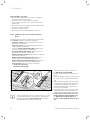
Fig. 5.25 Fastening the longer bottom side sections
i
30
If you are fitting two or more collectors next to or on top
of one another, then proceed initially by attaching the
intermediate plates (¬ Figs. 5.26, 5.27). Then attach
the right hand side sections for each row.
> First fit the lower, longer side sections
(¬ Table 5.1/5.3, Item 24/25).
> Remove the film from the longer side sections.
> Slide the left hand longer side section over
the first collector in the lower horizontal
row.
> Take care that the respective side section
is resting flush with the lower edge of the
collector and is engaged, as any subsequent movement will no longer be possible, due to the adhesion.
> Fit the right hand long side section to the
right hand collector on the bottom horizontal row in the manner just described.
> Fix the longer side sections to the roof
battens with the supplied brackets (1).
(¬ Table 5.1/5.3, Item 31) and No. 2
screws (¬ Table 5.2/5.4) using the Torx
bit.
Installation manual auroTHERM 0020100606_01
Assembly 5
> Press the vertical intermediate plate
(¬ Table 5.1/5.3 Item 28) into the vertical
space between the collectors. Take care
that the perforation is flush with the lower
edge of the collector at the bottom.
> Bend the plate downwards (¬ Fig. 5.26)
so that it reaches under the edge of the
collector and ends flush with it.
Fig. 5.26 Attaching the vertical intermediate plates
> Pick up one or more horizontal intermediate plates. Proceed according to the following criteria:
3
2
2
1
Number of
collectors on
top of one another
2
Number of
collectors
next to one another
Item number of the plate
from Table 5.1 / Table 5.3
1 x No. 19, 1 x No. 20
Item number of the plate
from Table 5.1 / Table 5.3
3
1 x No. 19, 1 x No. 20, 1 x No. 21
4
1 x No. 19, 1 x No. 20, 2 x
No. 21
n
1 x No. 19, 1 x No. 20, n x
No. 21
Fig. 5.27 Fastening the intermediate plates (here, horizontal)
Only when two VFK Hs are on top
of one another
– An intermediate plate with the number 36
from Table 5.3.
> Slide the horizontal intermediate plate
between the edge of the collector and the
spacer for the upper collector (2).
> Slide the plate over the upper edge of the
lower collector until it can be felt locking.
> Slide the intermediate plates together at
the cross joint (1).
The first plate on the left and the last plate
on the right must rest flush on the respective
collectors (3).
Installation manual auroTHERM 0020100606_01
31
5 Assembly
1
2
Fig. 5.28 Fastening the shorter top side sections
Attaching trapezoidal plates, connectors,
ridge sheets and tile supports
4,5
5.5.7
> Remove the film from the short side sections.
> Slide the short side sections
(¬ Table 5.1/5.3, Item 22/23) over the
collectors at the left and right in the
uppermost horizontal row.
> Take care that the respective side section
– rests on the collector frame,
– is pushed together with the lower side
section at the fold (1). Push the fold on
the lower side section apart a little for
this.
> Press the side section on to the side section so that it locks.
> Fasten the side sections to the roof battens with the supplied brackets (2)
(¬ Table 5.1/5.3, Item 31) and No. 2
screws (¬ Table 5.2/5.4) using the Torx
bit.
3
2
1
The trapezoidal plate (1) (¬ Table 5.1/5.3,
Item 27) covers the area (the "cross") in
which the interstices of four collectors meet.
> Slide a trapezoidal plate with the strap
under the vertical intermediate plate (1).
> Slide the trapezoidal plate forward until
the bent edges rest on the horizontal
intermediate plates.
> Drill a hole through the opening at the
upper end of the trapezoidal plate into the
intermediate plates underneath (2).
> Rivet the trapezoidal plate to the intermediate plates (3).
Fig. 5.29 Attaching the ridge plates
32
Installation manual auroTHERM 0020100606_01
Assembly 5
3
2
1
Fig. 5.30 Fitting additional roof battens as required
The space between the uppermost collector
(1) and the ridge is required for the ridge
plate couplers (2) on which the ridge plates
are then laid. To create a level surface, it may
be necessary to fit several roof battens (3).
> Attach a lower ridge plate coupling (2)
(¬ Table 5.1/5.3, Item 16) and check for a
level surface.
> Fit one or two additional roof battens (3)
(¬ Table 5.1/5.3, Item 13) and check that
the drill holes in the ridge plate couplings
align with the battens.
> Lay the ridge plate couplings aside and
screw the roof battens down firmly. Make
sure when doing this
– that the roof battens are resting flush
against the outer edge of the collector,
– that the roof battens terminate in the
middle of a rafter and abut with the
next batten.
s With vertical collector position
4
max
3
150
2
1
Fig. 5.31 Fitting lower ridge plate couplings (vertical collector)
Installation manual auroTHERM 0020100606_01
> Attach the lower ridge plate couplings
(¬ Table 5.1/5.3, Item 16) above the
collector:
– one on the external edge
(max. 150 mm from the edge),
– one per collector joint (central).
> Make sure that the lower ridge plate couplings are resting on the collector frame
slot (1).
> Slide a support board (¬ Table 5.1,
Item 18) through the straps on the lower
ridge plate coupling (2).
> Join the lower ridge plate couplings to the
support board with two No. 2 screws each
(¬ Table 5.2/5.4) using the Torx bit to
prevent it from slipping (3).
> Screw the lower ridge plate coupling at
the top to the roof batten (4).
33
5 Assembly
w With horizontal collector position
1066
max
150
4
1
3
1066
2
Fig. 5.32 Fitting lower ridge plate couplings (horizontal collector)
1
2
Fig. 5.33 Mounting the ridge plates
4
1
3
1
2
Fig. 5.34 Screwing down the ridge plates and attaching the upper ridge
plate couplings
34
> Attach the lower ridge plate couplings
(¬ Table 5.1/5.3, Item 16) above the
collector:
– one on the external edge
(max. 150 mm from the edge).
– in the centre of the collector
(1066 mm from the edge).
– one per collector joint (central).
> Make sure that the lower ridge plate couplings are resting on the collector frame
slot (1).
> Slide a support board (¬ Table 5.3,
Item 18) through the straps on the lower
ridge plate coupling (2).
> Join the lower ridge plate couplings to the
support board with two No. 2 screws each
(¬ Table 5.2/5.4) using the Torx bit to
prevent it from slipping (3).
> Screw the lower ridge plate coupling at the
top to the roof batten (4).
> Remove the protective film from the ridge
plates (¬ Table 5.1/5.3, Item 14, 15, 10).
> Slide the ridge plates (1) over the lower
ridge plate couplings.
> Make sure that the ridge plates are above
the side sections and slip into the corresponding rail (2).
> Start with a left hand ridge plate
(¬ Table 5.1/5.3, Item 14).
> If there are three or more collectors next
to one another, fit the corresponding
number of centre ridge plates
(¬ Table 5.1/5.3, Item 10) an.
> To finish, fit the right hand ridge plate
(¬ Table 5.1/5.3, Item 15).
> Fasten all the ridge plates to the roof
battens with the No. 1 screws
(¬ Table 5.2/5.4) using the Torx bit (1).
> Take the required number of upper ridge
plate couplers (¬ Table 5.1/5.3, Item 11).
An upper ridge plate coupling must be
screwed between each left hand, centre
and right hand ridge plate.
> Fasten all the upper ridge plate couplings
(2) above the ridge plate joint with two
No. 4 screws (¬ Table 5.2/5.4), Item (3)
in Fig. 5.34, and one No. 1 screw
(¬ Table 5.2/5.4), Item (4) in Fig. 5.34,
using the Torx bit.
Installation manual auroTHERM 0020100606_01
Assembly 5
2
4,5
1
> Drill a 4.5 mm diameter hole through the
markings in each of the left and right
hand ridge plates into the side sections (1).
> Rivet the ridge plates to the side sections (2).
Fig. 5.35 Riveting the frame
> Lay the tile supports (¬ Table 5.1/5.3,
Item 12) on the ridge plates.
> Bend the metal bands and hook the tile
bars to the roof batten above.
Fig. 5.36 Covering the profile ends with tile supports
> Cover the side profile ends and the collector joints from below with the end caps
(¬ Table 5.1/5.3, Item 32).
> To do this, attach the end caps at the bottom.
> Then tilt the end caps upwards until they
can be felt engaging on the upper edge of
the collectors.
Fig. 5.37 Fitting the end caps
Installation manual auroTHERM 0020100606_01
35
5 Assembly
5.5.8
Re-covering the roof
> Remove the protective film from the adhesive surface of the flexible apron
(¬ Table 5.1/5.3, Item 17).
> Adapt the flexible apron to the shape of
the tiles.
> Stick the flexible apron where parts overlap (1).
1
+5°C – +40°C
Fig. 5.38 Adapting the flexible apron
i
Make sure that the adhesive surface is dry and free from dust and
grease.
> As required, (e.g. with high roof tiles)
stick the sealing apron extension under
the flexible apron. Pay attention to the
direction the rain water flows in when
doing this.
> Turn the flexible aprons back at the ends
of the collector array.
i
Make sure that the adhesive surface is dry and free from dust and
grease.
+5°C – +40°C
Fig. 5.39 Sticking the flexible protection
> Stick the foam sealing wedge on the side
sections of the collector frame.
> Stick the foam wedge to the ridge plates.
> If necessary carefully cut the foam sealing
wedge with the utility knife.
>10 C
i
Make sure that the adhesive surface is dry and free from dust and
grease.
Fig. 5.40 Mounting the foam sealing wedge
36
Installation manual auroTHERM 0020100606_01
Assembly 5
1
2
3
> Close the free spaces between collector
and pantiles.
> Make sure that the pantiles at the side of
the collector array
– meet the central web (1) of the side sections,
– are positioned close over the foam sealing wedge (2),
– are stuck to the adhesive surfaces (3)
of the flexible apron.
> For dimensions please see Table 5.5.
> For this purpose use the removed tiles and
adapt them if necessary.
Fig. 5.41 Covering the roof
5.6
Checklist
Based on the following table, make sure all work steps
have been performed.
Step
1 All connections fixed with safety clips
2 Hydraulic connections laid correctly
3 Collector sensor connected
4 Collectors connected to lightning protection device
5 Pressure test carried out, all connections tight
6 Intact insulation
Table 5.6 Checklist
i
After commissioning and in seasons when
wide outside temperature fluctuations occur,
condensate can form in the collector.
This is normal.
i
Reflections caused by irregularities in the
glass are typical of the material.
Installation manual auroTHERM 0020100606_01
37
6 De-commissioning
6
De-commissioning
> Even when taking out of service and disassembling,
observe the
– Transport and handling instructions (¬ Chap. 3.1),
– Assembly instructions (¬ Chap. 3.2),
– Good engineering practice (¬ Chap. 3.3) and
– Accident prevention regulations (¬ Chap. 3.4).
a
Danger!
Danger of burning and scalding!
When exposed to solar irradiation, the inside
of the collectors can reach 200 °C.
> Avoid working in direct sunlight.
> Cover the flat collectors before starting
work.
> Preferably work during the morning.
> Wear suitable protective gloves.
> Wear suitable safety glasses.
The solar energy system should not be taken out of
service. The solar energy system can be taken out of
service for a short time for repairs or maintenance work.
b
b
38
Caution!
Risk of damaging the flat collectors!
Flat collectors that are not in operation can
age prematurely as a result of long-term high
standstill temperatures.
> Make sure that only a competent person
takes the solar energy system out of service.
> Take the flat collectors out of service for a
maximum of four weeks.
> Cover the flat collectors that are not in use.
> Make sure that the cover is securely fastened.
> Remove the flat collectors if you shut the
solar system down for longer periods.
6.1
Removing the flat collectors
b
Caution!
Damage to the flat collector and the solar
system!
Incorrect removal can cause damage to the
flat collector and the solar system.
> Before the flat collectors are removed,
make sure that only a qualified heating
engineer or Vaillant customer service technician takes the solar system out of service.
b
Caution!
Environmental hazard caused by solar fluid!
After the solar system has been taken out of
service, the flat collectors are still filled with
solar fluid which can escape during removal.
> During transport from the roof, close off
the pipe connections on the flat collector
with cover plugs.
>
>
>
>
>
>
>
>
>
Unfasten the hydraulic connections.
Unfasten the brackets.
Take the flat collector from the roof.
Remove the cover plugs.
Completely drain the flat collector into a canister via
both of the lower connections.
Insert the cover plugs again.
Deliver the solar fluid to a proper disposal facility
(¬ Chap. 7.3).
Pack the flat collectors adequately.
Deliver the flat collectors to a proper disposal facility
(¬ Chap. 7.1).
Caution!
Risk of oxidising the solar fluid!
If the solar circuit is opened during a long
period out of service, the solar fluid can age
prematurely as a result of the ingress of
atmospheric oxygen.
> Make sure that only a competent person
takes the solar energy system out of service.
> Take the flat collectors out of service for a
maximum of four weeks.
> Drain the entire system before a long
period out of service and dispose of the
solar fluid professionally.
> Remove the flat collectors if you shut the
solar system down for longer periods.
Installation manual auroTHERM 0020100606_01
Recycling and disposal 7
Warranty and customer service 8
7
Recycling and disposal
Both the appliance and its transport packaging are made
predominantly of recyclable raw materials. Please
observe the applicable national legal regulations.
7.1
Collectors
All Vaillant GmbH solar collectors comply with the
requirements of the German environmental label
"Blue Angel". Therefore, we, as the manufacturer, will
take back and recycle components when they have to be
disposed of after years of reliable use.
7.2
Packaging
The heating engineer who installed the equipment is
responsible for disposing of the transport packaging.
7.3
8
8.1
Warranty and customer service
Vaillant warranty
Vaillant provides a full parts and labour warranty for this
appliance.
The appliance and all associated pipe work and controls
must be installed by suitably competent persons in
accordance with all current and relevant safety, building
control and planning regulations and in full compliance
with the manufacturer’s instructions.
All unvented domestic hot water cylinders must be
installed by a competent person to the prevailing building regulations at the time of installation (G3).
Terms and conditions apply to the warranty, details of
which can be found on the warranty registration card
included with this appliance.
Failure to install and commission this appliance in compliance with the manufacturer’s instructions may invalidate the warranty (this does not affect the customer’s
statutory rights).
Solar fluid
8.2
The solar fluid must be disposed of at an appropriate
waste site or waste incineration plant, for example, in
compliance with local regulations.
Uncontaminated packaging can be reused. Dispose of
packaging that cannot be cleaned in the same way as for
solar fluid.
Installation manual auroTHERM 0020100606_01
Vaillant Service
To ensure regular servicing, it is strongly recommended
that arrangements are made for a Maintenance Agreement. Please contact Vaillant Service Solutions
(0870 6060 777) for further details.
39
9 Technical data
9
Technical Data
Unit
VFK 145/2 H/V
Absorber type
Dimensions (L x W x H)
VFK 155 H/V
Serpentine horiz./vert.
mm
2033 x 1233 x 80 (V)
2033 x 1233 x 80 (V)
1233 x 2033 x 80 (H)
1233 x 2033 x 80 (H)
Weight
kg
38
Volume
l
2.16 (H)
1.85 (V)
Max. pressure
bar
Stagnation temperature
°C
10
Gross area
m2
2.51
Aperture surface area
m2
2.35
Absorber surface area
m2
2.33
Absorber
mm
Aluminium (vacuum coated) 0.5 x 1178 x 1978
199
172
High selective (blue)
Coating
Glass covering
α = 95 %
ε = 5%
mm
Glass type
Transmission
Back wall insulation
%
3.2 (thickness) x 1233 x 2033
Solar safety glass
(prismatic structure)
Solar safety glass
(anti-reflection coating)
τ = 91
τ = 96
mm
W/m2K
kg/m3
Edge insulation
40
λ = 0.035
ρ = 55
none
available
%
80.1 (H)
79.1 (V)
84.2 (H)
83.3 (V)
Heat loss factor (k1)
W/m2K
3.32 (H)
2.41 (V)
3.82 (H)
2.33 (V)
Heat loss factor (k2)
W/m2K2
0.023 (H)
0.049 (V)
0.018 (H)
0.049 (V)
Efficiency ηo
Table 9.1 Technical data
40
Installation manual auroTHERM 0020100606_01
Technical data 9
VFK 145/2 V, VFK 155 V
80
1223
1233
79
80
5
2033
1875
1978
79
1178
Fig. 9.1 Dimensional drawing VFK 145/2 V, VFK 155 V
Installation manual auroTHERM 0020100606_01
41
9 Technical data
1233
1100
66,5
80
2033
1178
1223
5
66,5
VFK 145/2 H, VFK 155 H
1978
Fig. 9.2 Dimensional drawing VFK 145/2 H, VFK 155 H
42
Installation manual auroTHERM 0020100606_01
0020100606_01 GB 052013 – Subject to alterations