1
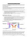
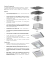
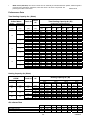
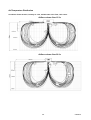
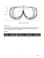
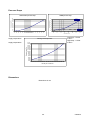
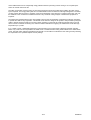
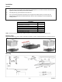
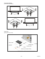
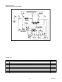
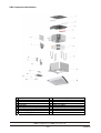
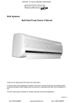
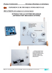
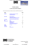
CBC
CHILLED BEAM CASSETTE
Int. Pat. App. WO 2005/015090
Specification, Application & Installation Manual
97408008-02
Index
Contents
Page
Part numbers.
2
Chilled beams – description and benefits.
3
Standard equipment, options and constructional details.
4
Cooling and heating capacities.
5
Air distribution, sound levels and weights.
6-7
Pressure drops and dimensions.
8
Application guidelines.
9
Installation, general details, mounting, blanking caps, chassis and fascia removal, fitting
valve tray.
10 - 11
Condensate drain.
12
Wiring diagram and check list.
13
Component identification.
14
Part Numbers
PART NUMBER
97400001
97400002
PART NUMBER
97400822
97400000
97400814
97400817
97400821
97400811
97400812
97400815
97400820
97400819
97200354
97400816
97400818
On Request
On Request
STANDARD COMPONENTS
DESCRIPTION
Chilled beam (inc gravity drain connector)
Fascia - (metal)
FACTORY OPTIONS
DESCRIPTION
Filter (to suit metal fascia)
Plastic fascia
Filter (to suit plastic fascia)
LPHW coil, High Temperature (80/70°C nominal)
LPHW coil, Medium Temperature (50/40°C nominal)
Electrics box (req'd if lift pump, light or valve is fitted)
*Lift pump (0.5m lift)
*Metal fascia with integral light fitting
*Metal fascia with integral light fitting & battery
backup
Blanking cap kit (to allow for side blanking)
Valve drip tray
*CW valve, two port on/off
*LPHW valve, two port on/off
∅100mm air Damper Kit
450mm x ½" Flexible Hose Kit
* Any combination of these items requires the
electrics box (part number 97400811) to be fitted.
2/14
97408008-02
The Quartz CBC Chilled Beam Cassette
Developed in conjunction with the Building Research Establishment at Garston, the Quartz CBC Chilled Beam Cassette
is a novel product that combines the many benefits offered by active chilled beam technology with the cost and space
saving advantages of cassette technology.
Active Chilled Beams
Once the concept of cooling by chilled beam had been proven and accepted using passive chilled beams, development
focused on increasing the beam capacity. By introducing the required fresh air through nozzles adjacent to the cooling
coil, room air could be induced through the coil. This induced flow substantially increased the beam's capacity. Such
devices became known as "Active Chilled Beams."
Active chilled beams provide many benefits to the end user over traditional methods of cooling and heating. Key benefits
are;
1)
2)
3)
4)
When cooling, the use of relatively high water temperatures results in a high-energy efficiency rating (EER) for
the chiller supplying the circuit, as well as providing substantial opportunities for free cooling in Northern
European climates. Analysis of the whole life cost of a chilled beam system shows it to be only 2/3 the cost of an
equivalent fancoil system and 1/2 the cost of a VAV system.
Due to the fact that there are no moving parts, maintenance and service requirements are substantially reduced.
Chilled beams are virtually silent in operation.
Chilled beams provide a better air distribution in the occupied space, with less draughts.
Specific Benefits of CBC Product
In addition to the general benefits described above, the CBC cassette offers further features: 1)
2)
3)
The CBC is one of the few active chilled beams with the facility for condensate collection and removal. This
enables water temperatures (and hence cooling effect) to be maintained when the room conditions are such that
condensate would be generated. Other chilled beams must stay "dry" and do so by increasing the water
temperature, with a resultant drop in cooling duty.
The unique construction of the CBC enables easy and complete removal of the chassis, by one person, from
within the occupied space, without disturbing the ceiling grid. Removal exposes both sides of the cooling coil
and the condensate tray for disinfection, a process that is essential in the health care sector.
By utilising standard suspended ceilings for mounting, the CBC can easily be moved within the grid to
accommodate changes of use of office space.
Description of Operation
(PRIMARY AIR)
INDUCED AIR
(SECONDARY AIR)
The Quartz Chilled Beam Cassette operates on the induction principle.
The building fresh air supply is treated (filtered, then heated or cooled) in an external air-handling unit. This treated fresh
air is introduced to the room via the chilled beam cassette, being discharged within the unit through specially designed
nozzles located around the periphery between the coil and the chassis. The flow of air from these nozzles causes a
reduction in pressure, thereby inducing a flow of air from the unit centre across the heat exchange coil(s). This air is
replaced by warm air from the room that rises by convection and enters the cassette via the central grille.
The main coil is supplied with cooling water and the optional LPHW coil (if fitted) with heating water. The induced air is
thus conditioned and mixed with the fresh air supply before discharging to the space via the four-way blow fascia.
3/14
97408008-02
Standard Components
The standard Quartz Chilled Beam Cassette consists of two components, a
chassis (part number 97400001) and a metal fascia (part number 97400002).
The condensate gravity drain connector is supplied loose as standard with each
unit.
Top panel
Options
A filter which, when fitted into the fascia, will remove dust from the return
air prior to passing through the coil.
Fresh air plenum
Two versions of LPHW coil are available that have been designed to
minimise stratification when using the CBC for heating. The coil type
selected is dependant upon the water temperature available for heating
(supply either 50°C or 80°C).
An electrics box that must be fitted if the lift pump, light fitting or valve
options are being used.
A lift pump that can achieve a lift of 0.5m. The pump controls provide a
high level alarm as standard.
Coil
A high efficiency light fitting, incorporated into the metal fascia. Using this
option enables the lighting and cooling grids to be combined in the ceiling
layout. There is also a version with battery back up that can be used in
areas requiring emergency lighting.
A blanking cap kit. The caps are fitted over the nozzles to reduce or
eliminate airflow from one side of the unit.
A valve drain tray kit. This tray screws onto the pipe panel and sits below
the control valves. Any condensate that forms on the valve body can thus
be removed.
Chassis
A low cost plastic fascia with discharge air deflectors fixed at 35° for
optimum performance. In addition, a filter for this fascia is also available.
Two port, 15mm control valves for chilled water and LPHW circuits. The
valves are fitted with 240V on/off actuators as standard.
Air damper kits for ∅100mm ducting. The standard kit has a manually
adjustable damper.
Metal fascia
Flexible hose kit that consists of two 450mm x ½" flexible hoses with
Speedfix connectors as standard.
Construction
Top Panel: The press-formed top panel to which all the main components
are attached, is manufactured from galvanised mild steel sheet.
Fresh Air Plenum: Moulded in medium density polyethylene. It has flame
retardancy properties that comply with the requirements of Class O.
Heat Exchange Coils: Manufactured from copper tubes and collar spaced
aluminium fins. By expansion of the copper tube, the fins are mechanically
bonded to the tubes, thereby ensuring maximum contact and optimum heat
transfer.
Metal fascia with light
Main Chassis: Moulding in medium density polyurethane foam that is
flame retardant to UL94-V0. The material is a poor conductor of heat
thereby eliminating the requirement for additional insulation. The
lightweight nature of the construction reduces the labour requirement for
installation and for cleaning.
4/14
97408008-02
Metal Fascia (Standard): The fascia is made from an assembly of extruded aluminium profiles, whilst the grille is
produced from perforated, galvanised, mild steel sheet. All fascia components are
Plastic fascia
painted gloss white to RAL 9010.
Performance Data
Total Cooling Capacity Qtc (Watts)
Chilled Water
Supply
Fresh air
Room
air
Total Cooling Capacity Qtc (W)
Differential
(°C)
(°C)
2
12
3
4
2
14
3
4
2
16
3
4
(°C)
(°C)
12
14
16
12
14
16
12
14
16
12
14
16
12
14
16
12
14
16
12
14
16
12
14
16
12
14
16
22
24
26
22
24
26
22
24
26
22
24
26
22
24
26
22
24
26
22
24
26
22
24
26
22
24
26
15 l/s
Qtc
Flow
(W)
(l/s)
Primary Air Volume Flow (l/s)
20 l/s
25 l/s
Qtc
Flow
Qtc
Flow
(W)
(l/s)
(W)
(l/s)
Qtc
(W)
30 l/s
Flow
(l/s)
504
0.038
670
0.051
835
0.063
997
662*
0.057
875*
0.075
1086*
0.093
1292*
839*
0.077
1092*
0.102
1213*
0.124
1497*
470
0.023
618
0.030
766
0.036
913
624*
0.035
824*
0.046
1014*
0.057
1180*
792*
0.049
1033*
0.063
1178*
0.077
1354*
450
0.016
595
0.021
736
0.026
871
573*
0.023
762*
0.031
942*
0.038
1127*
741*
0.033
981*
0.044
1104*
0.054
1263*
416
0.027
557
0.037
684
0.045
818
492*
0.037
665*
0.050
825*
0.062
987*
663*
0.056
881*
0.076
1085*
0.093
1173*
408
0.018
526
0.022
658
0.028
773
467
0.022
618
0.030
755
0.036
913
625*
0.035
828*
0.046
1016*
0.057
1104*
403
0.013
506
0.016
615
0.019
745
450
0.016
595
0.021
728
0.025
879
577*
0.023
764*
0.031
947*
0.038
1065*
353
0.020
463
0.026
573
0.032
683
419
0.027
545
0.036
677
0.044
819
496*
0.037
655*
0.049
810*
0.061
977*
339
0.012
432
0.015
532
0.018
631
391
0.017
530
0.021
648
0.027
783
470
0.022
622
0.030
756
0.036
913
316
0.008
404
0.010
501
0.012
604
382
0.012
505
0.016
617
0.019
736
450
0.016
585
0.021
728
0.025
867
* Denotes duty points where condensate may form on the coil
0.075
0.111
0.148
0.044
0.066
0.092
0.031
0.045
0.065
0.054
0.074
0.112
0.033
0.043
0.068
0.023
0.031
0.045
0.038
0.053
0.072
0.022
0.033
0.043
0.014
0.022
0.029
Heating Capacity Qth (Watts)
LPHW
Supply
Fresh air
(°C)
80
70
(°C)
20
22
45
20
22
50
Heating Capacity Qth (W)
Return
(°C)
50
Room
air
40
20
22
(°C)
20
22
22
20
22
22
20
22
22
15 l/s
Qth
Flow
(W)
(l/s)
Primary Air Volume Flow (l/s)
20 l/s
25 l/s
Qth
Flow
Qth
Flow
(W)
(l/s)
(W)
(l/s)
30 l/s
Qth
Flow
(W)
(l/s)
610
556
584
523
449
482
404
331
365
0.016
0.013
0.013
0.025
0.021
0.021
0.010
0.008
0.008
726
665
693
634
548
585
512
417
458
0.017
0.016
0.016
0.030
0.026
0.026
0.012
0.010
0.010
832
761
796
736
635
671
608
493
534
0.020
0.018
0.018
0.035
0.030
0.030
0.015
0.012
0.012
937
859
892
838
709
766
696
556
622
0.022
0.030
0.030
0.040
0.034
0.034
0.017
0.013
0.013
l/s
m³/h
l/s
m³/h
l/s
m³/h
l/s
m³/h
15
28
43
54
100
154
20
37
57
72
134
206
25
46
71
90
167
257
30
56
86
108
200
308
Air volume flow
Primary (Fresh) Air
Secondary (Room)
Total Supply Air
5/14
97408008-02
Air/Temperature Distribution
Conditions: Room air 24°C, Primary air 14°C, Chilled water 14°C Flow, 16°C return
Airflow volume flow 15 l/s
Airflow volume flow 20 l/s
6/14
97408008-02
Airflow volume flow 25 l/s
Sound Levels
The maximum sound pressure level (measured 1m down and 1m away from the centre of the unit, in a room
of 32m³ volume and with a reverberation time of 0.5 seconds) is 32dB(A) (NR27) with a primary air volume
of 30l/s. At lower primary air volumes, the sound Pressure level is in the order of 28dB(A) (NR23-25).
For further details contact TEV Applications Department.
Weights
Item
CBC
Metal Fascia
Packed Weight (kg)
16
7
Unpacked Weight (kg)
15
5
7/14
Coil Water Volume (litres)
0.5
Operating Weight (kg)
15.5
5
97408008-02
Pressure Drops
LPHW pressure drop
Chilled water pressure drop
100
6
Low temp
80
Unit pressure drop kPa
Unit pressure drop kPa
90
70
60
50
40
30
20
5
4
3
2
1
High temp
10
Duct pressure Pa
0.040
170
160
150
140
130
120
110
100
90
80
70
60
50
40
30
20
16
0.035
Low temp – LPHW
of 50°C
High temp – LPHW
of 80°C
Primary air duct pressure
15
0.030
LPHW flow rate l/s
supply temperature
supply temperature
0.025
Chilled water flow rate l/s
0.016
0.014
0.012
0.15
0.14
0.13
0.12
0.11
0.1
0.09
0.08
0.07
0.06
0.05
0.04
0.03
0.02
0.01
0.010
0
0
17
18
19
20
21
22
23
24
25
26
27
28
29
30
Primary air volume l/s
Dimensions
Dimensions in mm
8/14
97408008-02
LPHW IN
CW IN
610
LPHW OUT
CW OUT
LIFT PUMP
OUTLET (IF FITTED)
298
34
300
150
600
150
40
Ø 15
BLEED SCREW
150
98mm Ø
FRESH AIR SPIGOT
FOR PRIMARY
AIR SUPPLY
ELECTRICS BOX
(IF FITTED)
Min 580x580
GRAVITY DRAIN
CONDENSATE OUTLET
40
Application Guidelines
Selection of Units
Active chilled beams may be selected and applied in a similar manner to fancoils. It is important to ensure that, at any
given condition, sufficient units are chosen to meet the cooling load. With fresh air supply rates of 12 l/s per person and
one person per 5m2, the CBC will cater for loadings of 70-90 W/m2. Typically, a single CBC will be required for every
10m2 in this arrangement.
Lower loadings will obviously require fewer units and, in such instances, provision for extra fresh air supply may have to
be made.
Higher loadings that require more than one unit per 10m2 can be catered for, but care must be taken that airflows from
adjacent units do not impinge on each other and "dump" (refer to airflow diagrams). Blanking caps are available to reduce
or eliminate the airflow from one side of the unit.
If the unit is to be installed close to a wall (typically nearer than 1.5m), the discharge from the side nearest to the wall
should be blanked off.
Note that the noise data provided is for a single unit and that most applications will require multiple units in the zone. A
correction for the effect of adjacent units must be made.
Controls & Valves
The output of the CBC may be controlled in two ways. The main method of control is by variation of the water flow to the
cooling coil; however, it is also possible to adjust the capacity by variation of the primary air supply.
Where an area has continuous occupation during working hours, the CBC can be controlled by variation of the water
flow. This can be either simple on/off valves or more sophisticated modulation of the flow with respect to distance from
set point. Each CBC can be fitted with a valve and controlled individually. However, in larger zones that have multiple
CBC units, a single valve can control a group of units. This is the most cost effective means of performing group control,
although it can also be achieved using relay boxes switching multiple individual valves.
In areas with intermittent occupancy (meeting rooms, for instance), control of both water and primary air will be required.
When fully occupied, the control method will be by variation of the water flow as described above. When the occupancy
level drops or disappears, the reduction in load will cause the valve to close. The primary air however, being supplied at a
low temperature, will continue to cool the room. The controller must recognise this and close off the primary air supply to
prevent over cooling the room. Sophisticated systems will further detect the increase in duct static pressure and, by
means of speed controllers on the AHU motor, reduce the overall fresh air supply.
Energy Efficiency & Free Cooling
9/14
97408008-02
Active chilled beams are an exceptionally energy efficient method of providing comfort cooling to an occupied space.
There are several reasons for this.
The CBC unit operates using the energy of the fresh air supply that must be provided to the building. No other energy
input is required. The energy used by the fan in a traditional fancoil is thus saved and, although this appears to be small,
on large projects with long hours of operation, it becomes substantial. It must be borne in mind that the energy use over
the entire life of the unit must be considered and this is why whole life costing analysis of chilled beam projects is so
important.
The higher water temperatures that are used (initially to prevent the coil generating condensate) provide the opportunity
to operate the chiller at very high EER's. This benefit can be lost if the design of the system is compromised by using the
chiller to temper the fresh air with 6/12°C water. Ideally, tempering of the fresh air would be performed using a DX coil
with an inverter controlled condensing unit, whilst the chiller is dedicated to supplying the chilled beam circuit with high
temperature (14°C) water.
If 14°C water is used, a substantial opportunity to generate this by free cooling exists in Northern European climates.
Either a dry cooler can be incorporated in the water circuit or a dedicated free cooling chiller utilised for the chilled beam
circuit. The latter option will have specialised controls built in to the chiller to maximise the free cooling, thereby obviating
the requirement for a specialist bespoke control package.
10/14
97408008-02
Installation
General
1.
CBC units must only be installed and maintained by qualified persons, in accordance with all national and local
regulations relating to plumbing and electrical installation.
2.
The data plate only gives information for the CBC unit.
3.
TEV Ltd recommend that personnel working on this equipment be skilled and fully conversant with the
appropriate air conditioning and electrical practices and have sound knowledge of current industrial safe
working practices.
CONTENTS
PARTS DESCRIPTION
Installation instruction
and Declaration of Conformity
Fascia assembly (inc 4 x screw / washer)
Template
Hanging bracket
Washer
Screw
Drain Connector (inc ‘O’ ring)
QUANTITY
1
1
1
2
8
4
1
NOTE: The unit can be installed with the chassis in position or removed prior to installation for easier access.
Blanking Caps
(These can be fitted to any of the 4 sides of the plenum chamber to reduce or eliminate airflow from one side of the unit)
Mounting
11/14
97408008-02
Fascia And Chassis
(optional removal and refitting)
Valve Tray
(option when a valve is fitted)
12/14
97408008-02
Condensate Drain
(If fitted)
GRAVITY DRAIN
<5m
< 1.5 m
> 1:100
80 mm
X
Remove
Remove drain
plug and fit
drain adapter
6 mm
Fit
OIL
15 mm o.d.
(Cu)
16 mm
0.5m LIFT PUMP
< 150mm
< 1500mm
> 1:100
< 650mm
X
15 mm o.d.
> 50 mm
OIL
12 mm i.d.
TESTING
GRAVITY DRAIN
1L
13/14
PUMP
97408008-02
Wiring Diagram
Electrics Box & Lift Pump (if fitted)
Check List
Checked
1
Is the unit square and level with the ceiling?
2
Is the pipework correctly supported throughout its length?
3
Are the chilled water pipes insulated right up to the unit?
4
Have all pipework joints been carefully checked for leaks?
5
Is the condensate drain correctly sized, connected, supported and insulated?
6
Has the effectiveness of condensate removal system been tested and there are no leaks?
7
Is the air distribution as required?
8
Is the fresh air ductwork connected?
14/14
97408008-02
CBC Component Identification
1
2
3
4
5
6
7
8
9
Top panel
Hanging brackets (2 off)
Fresh air plenum
Blanking caps (option)
Pipe panel
Cooling coil heat exchanger
Lift pump (option)
LPHW coil (option)
Coil bracket (4 off)
10
11
12
13
14
15
16
17
18
Electrics box cover (option)
Terminal block (option)
Electric box (option)
2 port valve (option)
Valve tray (option)
Gravity drain adaptor
Hose (supplied with valve tray)
Chassis
Metal Fascia
TEV LTD, ARMYTAGE ROAD, BRIGHOUSE, WEST YORKSHIRE, HD6 1QF. TEL: + 44 (0) 1484 405630 FAX: +44 (0) 1484 405620
EMAIL: [email protected] WEB: www.quartz.co.uk
15/14
97408008-02