1
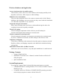
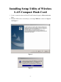
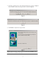
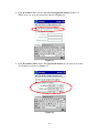
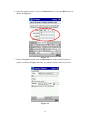
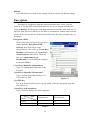
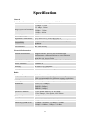
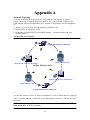
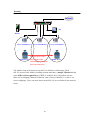
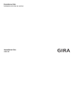
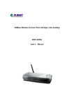
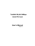
Wireless Compact Flash Card
Users Guide
Before operating the unit, please read this manual and retain it for future
1
Contents
Introduction ........................................................................................3
Features and Benefits ...................................................................3
Wireless Solutions and Application..............................................4
Package Contents .........................................................................4
System Requirements ...................................................................4
Ins talling Setup Utilit y of Wireless LAN Compact Flas h Card ..........5
Wireless LAN Setting..........................................................................9
Us ing the Wireless LAN Utility .........................................................12
Specification......................................................................................17
Appendix A .......................................................................................19
Network Topology ......................................................................19
Appendix B ....................................................................................... 22
2
In troduction
This product is an IEEE 802.11b Wireless Compact Flash Adapter that uses a
standard Type I CF adapter interface which integrated with wireless LAN technology.
It provides an easy and fast way to access the Internet via wireless network. This
Wireless Compact Flash adapter allows the users to install on PDAs (Personal Digital
Assistants), Pocket/Handheld PCs and other devices equipped with a Type I CF slot.
This Compact Flash Card is 802.11b compliant and the data rate of connection is up
to 11Mbps. With an 802.11b Compact Flash Card you can send and receive E- mail,
synchronize with your desktop computer, and surf the Internet while on the move.
Features and Benefits
11Mbps data transfer rate
IEEE 802.11b compliant
High-speed data transmission
Fully interoperable with IEEE802.11b compliant
products
Automatic data rate scaling at
11, 5.5, 2 and 1 Mbps
Optimized throughput, range and connectivity
Wired Equivalent Privacy
(WEP) encryption and
decryption support
Powerful data security at 64 and 128 bits
Supports a variety of popular computing devices
Compact Flash Type-I standard such as PDA, Pocket PC, Tablet PC, Webpad and
Handheld device
Supports both Pocket PC and
Flexible to work with both your PDA and your
Windows PC operating systems notebook PC
Wide coverage range up to 300
meters in open space
Wireless connectivity for all your computers
Advanced Power Management
and Suspend on WLAN
Very low power consumption delivers extended
battery life for client devices
Plug and Play Compact Flash
Type-I interface
Easy installation
Significantly improved indoor
multipath distortion
Seamless roaming
Higher link quality in indoor environment
Full mobility
Direct Sequence Spread Spectrum
Provides robust, interference-resistant, and secure
(DSSS) technology
wireless connection
3
Wireless Solutions and Application
Access existed networks for mobile workers
Allow doctors, nurses, sales access their database while keeping mobility in the
hospitals, retail stores, office campus or other buildings.
Difficult-to-wire environment
There are many situations where wires cannot or cannot easily be laid. Historic
buildings, older buildings, open areas and across busy streets make the installation
of LANs either impossible or very expensive.
Frequently changed environment
Show rooms, meeting rooms, retail stores, and manufactur ing sites where the
workplace located are frequently rearranged.
Wired LAN backup
Network managers implement wireless LANs to provide backup for
mission-critical applications running on wired networks.
Wireless extensions to wired networks
Network managers in dynamic environments can minimize the overhead caused
by moves, extensions to networks, and other changes with wireless LANs.
Temporary workgroup
Trade shows, exhibitions, and construction sites that require a temporary network.
Retailers, airlines, and shipping companies need additional workstations during
peak periods.
Small Office/ Home Office (SOHO) Networks
SOHO users need a cost-effective, easy and quick installation of a small network.
Package Contents
Ÿ
Ÿ
Ÿ
Compact Flash Card Unit
Installation CD (Include User’s Manual, Acrobat® Reader and Packet PC
Utility Program)
Quick Installation Guide
System Requirements
For using this Compact Flash Card, the following requirements are needed:
Ÿ A Handheld/Pocket PC running Windows CE 3.0 with an available Compact
Flash Type I slot.
Ÿ A computer which uses Windows 95/98/ME/2000/XP operating system has
an ActiveSync program to connect with the Pocket PC
4
In stalling Setup Utility of Wireless
LAN Compact Flash Ca rd
1. Create a connection between Hand PC and Desktop/Laptop by Microsoft Active
Sync.
2. Install the PDA’s driver and utility by executing CFDR.exe as shown in Figure1
and Figure 2.
Figure 1
Figure 2
5
3. After the Install Shield Wizard window appears, click Next to continue as shown
in Figure3.
Figure 3
4. In the Software License Agreement dialog window, click Yes to accept all the
terms of the License Agreement as shown in Figure4.
Figure 4
6
5. Click Yes to install the driver in the default install directory as shown in Figure 5,
then click OK to continue the setup procedure as shown in Figure 6.
Figure 5
Figure 6
6. Click Finish to complete the setup procedure.
Figure 7
NOTE: Insert the Wireless Compact Flash card to the PDAs AFTER the Setup
Utility and Driver ’s installation procedure.
7
7. Start the Microsoft ActiveSync to check the installation status of the PDAs. In the
Microsoft ActiveSync dialog window, click Tools and then choose Add/
Remove Programs to check out the drivers or programs that has been installed as
shown in Figure 8.
Figure 8
8
Wireless LAN Setting
1. Connect the wireless compact flash card to PDAs.
2. Select StartàSettings on the handheld. In the Settings dialog, click Connections
and then click Network icon as shown in Figure 9.
Figure 9
3. In the Adapter tab, choose 802.11b WLAN 11Mbps Wireless LAN PC to set up
the IP address as shown in Figure 10.
Figure 10
9
4. In the IP Address label, choose Use server-assigned IP address if there is a
DHCP server in your own network as shown in Figure 11.
Figure 11
5. In the IP Address label, choose Use specific IP address if you need to set up the
fix IP address as shown in Figure 12.
Figure 12
10
6. After the setting of Step 5, move to Name Servers to set up the DNS server as
shown in Figure 13.
Figure 13
7. Choose Use proxy server in the Connections tab of the Internet Explorer’s
options as shown in Figure 14 when you connect Internet via Proxy Server.
Figure 14
11
Using the Wireless LAN U tility
This Wireless Compact Flash Adapter is a “ready-to-use” device. The default
settings have finished for a typical Infrastructure Wireless LAN. After installing
the Setup Utility and the Driver into the handheld devices, simply install the Wireless
LAN Compact Flash Card onto your handheld devices and it is ready to use. In some
situations, however, you may want to adjust the configuration settings to manage
your wireless network. The Wireless LAN Utility of this Compact Flash Card
provides you to make the configuration changes by an easily interface. If you need to
adjust the settings, please following the instructions below.
Status
State
This item shows status information about the radio link as shown in Figure 15.
Ÿ Associated BSSID – means the wireless client is
connected to an access point. BSSID is shown
in the form of six hex digits which is the MAC
address of the access point.
Ÿ Scanning – means the wireless client is
searching for an available access point in
infrastructure mode.
Ÿ Disconnected – means there are no access
points or other wireless clients (if
communicating in Ad-hoc mode), or the PC
Card is unplugged in your computer.
Current Tx Rate (Mbits/s)
The data speed that wireless client is
transmitting.
Figure 15
Current Channel
The operation radio frequency channel that wireless client is using in
infrastructure mode. In infrastructure mode, wireless client will always go the
same channel as their Access Point.
Throughput (Bytes/sec)
Tx: shows the outgoing (sent) data speed.
Rx: shows the incoming (received) data speed.
12
Link Quality
In infrastructure mode, this bar displays the transmission quality between a
WLAN station (Access Point) and Wireless LAN PC Card. In Peer-to-Peer mode
(Ad-Hoc), this bar displays the link quality between two Wireless LAN PC Cards.
Signal Strength
This bar displays the signal strength level. The higher bar is, the more powerful
radio signal is received by the PC Card.
Disable/Enable Radio
This button is used like a switch that allows users to turn off the wireless radio by
clicking this button and turn it on again.
Rescan
The radio will rescan all available channels by pressing this button. You can push
this button to rescan the channels for better link quality when the link quality is
poor.
Configuration
Make configuration changes by specifying the proper configuration
parameters on this configuration tab as shown in Figure 16.
Profile
You can give a name for this field to a setting of
configuration parameters, such as Network
Name, Network Type, Transmit Rate,
Encryption (WEP Security), etc. It makes much
easier for users to change WLAN configuration
settings who need to switch working places
frequently. Suppose that a user has to work
between the two different offices where there
are different network settings. In this case, this
user just needs to setup two profiles for the two
offices and simply selects the proper profile
when the user switches to the different office.
Figure 16
Network Name
For infrastructure mode, you need to type in the SSID of the access point to which
your computer connects. For Ad-Hoc (peer-to-peer) mode, you need to type in the
virtual SSID of the Ad-Hoc network to which your computer attaches.
Network Type
There are two types of network modes in this drop-down list, Peer-to-Peer and
Access Point (Infrastructure).
13
Ÿ Peer to Peer: If two or more stations exchange data directly without an access
point, you need to select Peer-to-Peer mode. Each station in a Peer-to-Peer
(Ad-Hoc) network must specify the same network name (SSID) and
peer-to-peer channel.
Ÿ Access Point: If at least one access point involves in the communications in a
group of stations, you need to select Infrastructure mode. Each station needs to
specify the same network name (SSID) as the access point.
Peer-to-Peer Channel
This option is just for Peer-to-Peer (Ad-Hoc) mode. You need to specify a
channel on which the communications are established. Each station in a
Peer-to-Peer (Ad-Hoc) network must specify the same channel and network type
(SSID).
Power Save Mode
Power Save function as shown in Table 1 .This function can conserve more
battery energy and extend the battery life. This function has three options for
power save mode. Below is detailed description.
On:
Off:
Auto:
Enable Power Save function.
Disable Power Save function.
Utility will automatically detect what kind of
power supply a machine uses and then determine
to enable or disable Power Save function.
If device uses battery, Power Save Mode is set to
on.
If device uses AC Power, Power Save Mode is
set to off.
Table 1
Transmit Rate
The transmission rate on which the data packets are transmitted by the client can
be specified in this drop-down list as shown in Table 2. Below are the available
transmission rates.
Full Automatic
11 Mbps
5.5 Mbps
Auto 1 or 2 Mbp
PC Card chooses the highest
available transmission rate
allows only 11 Mbps operation
allows only 5.5 Mbps operation
allows only 1 or 2 Mbps operation
Table 2
14
Defaults
Once this button is pressed, all the settings will be set back to the default settings.
Encryption
Encryption is designed to make the data transmission more secure. you can
select 64 or 128-bit WEP (Wired Equivalent Privacy) key to encrypt data (Default
setting is Disable). WEP encrypts each frame transmitted from the radio using one of
the Keys from this panel. When you use WEP to communicate with the other wireless
clients, all the wireless devices in this network must have the same encryption key or
passphrase .
Encryption (WEP)
Choose one of the encryption key (64 bit or
128bit) from the Encryption (WEP
Security) drop-down list to create
encryption key. Click either on Create Keys
Manually radio button or on Create Keys
with Passphrase radio button. There are
two ways, Alphanumeric and
Hexadecimal, to set the different characters
as shown in Table 3.
Create Keys Manually: Alphanumeric
Type 5/13 alphanumeric characters in the
key field
Create Keys Manually: Hexadecimal
Type a 10/26 hexadecimal numbers (1-9;
A-F) in the key field
Figure 17
Use WEP Key
This drop-down list allows you to specify which of the four encryption keys that
you want to use.
Create Keys with Passphrase
Type a character string in the field Passphrase.
Data
Mode
64 bit
128 bit
Alphanumeric
Hexadecimal
5
13
10
26
Table 3
15
Disabled
Select Disabled item in the Encryption (WEP ) drop-down list allows you to
disable the encryption function.
Site Survey
Browse the available access points in your
network environment by clicking the Scan button
and make a connection to one of them by pushing
the Connect button in the Site Survey tab as
shown in Figure 18.
Figure 18
About
About tab shows the product/driver/utility/PC
Card firmware version as shown in Figure 19.
Users have to use this version number when
reporting their problems to technical support.
Figure 19
16
Specifica tion
General
Radio Data Rate
11, 5.5, 2 and 1 Mbps, Auto Fall- Back
11 Mbps –150m
5.5 Mbps –200m
Range (open environment)
2 Mbps – 300m
1 Mbps –400m
Operating Voltage
Regulation Certifications
3.3V
FCC Part 15/UL, ETSI 300/328/CE
Compatibility
Fully interoperable with IEEE802.11b compliant
products
LED Indicator
RF Link activity
Network Information
Network Architecture
Support ad-hoc, peer-to-peer networks and
infrastructure communications to wired Ethernet
networks via Access Point
Driver Software Support
Access Protocol
Windows XP/ME/2000/98/CE 3.0/PocketPC 2002
CSMA/CA
Roaming
IEEE802.11b compliant
Security
64/128-bit WEP data encryption
Radio
Frequency Range
U.S., Europe and Japan product covering 2.4 to 2.484
GHz, programmable for different country regulations
Radio Type
Modulation
Direct Sequence Spread Spectrum (DSSS)
CCK (11, 5.5Mbps)
DQPSK (2Mbps)
DBPSK (1Mbps)
Operation Channels
11 for North America, 14 for Japan,
13 for Europe, 2 for Spain, 4 for France
RF Output Power
13dBm
Antenna
Integrated, with built- in diversity
Sensitivity @FER=0.08
11 Mbps <-85dbm ; 5.5 Mbps <-87dbm
2 Mbps <-89dbm ; 1 Mbps <-91dbm
17
Environmental
Temperature Range
Humidity
-10°C to 50°C (14°F to 122°F)-operating
-30°C to 80°C (-22°F to 176°F)-storage
95% maximum non condensing
Physical Specifications
Form Factor
Dimensions
Fits Compact Flash Type-I Slots
55.4(L) mm x 42.8(W) mm x 3.3(H) mm
2.18(L) in x 1.69(W) in x 0.13(H) in
Weight
45.36 g/ 1.6oz
18
Appendix A
Network Topology
To better understand how the wireless LAN products work together to create a
wireless network, it might be helpful to depict a few of the possible wireless LAN
USB Adapter network configurations. The wireless LAN products can be configured
as:
1. Ad-hoc (or peer-to-peer) for departmental or SOHO LANs.
2. Infrastructure for enterprise LANs.
3. IP Sharing for 56K/ISDN TA/Cable/DSL Modem – Connect Internet and your
SOHO network.
Ad-Hoc Wireless Network
Laptop with Wireless LAN Card
PDA with CF Card
Desktop with Wireless USB Adapter
Ad-Hoc Wi reless LAN
Desktop with Wireless USB Adapter
PDA with CF Card
Laptop with Wireless LAN Card
1
An Ad-Hoc wireless LAN is a group of computers as well as PDAs that are equipped
with a wireless adapter, connected as an independent wireless LAN (Local Area
Network).
NOTE: Must configure all wireless devices in the same Radio Cha nnel, SSID and
Encryption Key (if WEP is enabled).
19
Infrastructure Wireless Network
Internet
PC
Server
Wireless Broadband Router/ AP
Desktop with Wireless USB Adapter
PDA with CF Card
Laptop with Wireless LAN Card
All of the Senao’s wireless devices provide access to a wired LAN through the
wireless extension of the local network. An integrated wireless and wired LAN by
using the Access Points is called an Infrastructure configuration.
Infrastructure configuration allowed users extend the accessibility of the wireless
and wired LAN. Multiple 802.11b Access Points will allow roaming and will increase
the effective transmission range.
20
Roaming
Internet
PC
Server
Access Point/Router
Access Point/Router
Access Point/Router
Wireless device roams
Mobile Device between APs while
maintaining uniterrupted
Mobile Device
network connectivity
The mobile client will connect to any 802.11b AP that is within range. Each
802.11b Access Point within a roaming network must have a unique Channel and the
same SSID and Encryption Keys (if WEP is enabled). 802.11b products can use
three non-overlapping Channels within the same vicinity (Channels 1, 6, and 11 are
non-overlapping). Users can move between the 802.11b Access Points in the network
freely.
21
Appendix B
Radio Frequency Interference Requirements
This device complies with Part 15 of FCC Rules and Canada RSS-210.
Operation is subject to the following conditions:
1. This device may not cause harmful interference.
2. This device must accept any interference received, including interference
that may cause undesired operation.
3. To comply with RF safety requirements, you must maintain a distance of 20
cm from the antenna when operating the device.
4. This transmitter must not be co-located or operating in conjunction with any
other antenna or transmitter.
Interference Statement
This equipment has been tested and found to comply with the limits for a Class B digital device,
pursuant to Part 15 of the FCC Rules, These limits are designed to provide reasonable
protection against harmful interference in a residential installation. This equipment generates,
uses and can radiate radio frequency energy and, if not installed and used in accordance with
the instructions, may cause harmful interference to radio communications. However, there is
no guarantee that interference will not occur in a particular installation. If this equipment does
cause harmful interference to radio or television reception, which can be determined by turning
the equipment off and on, the user is encouraged to try to correct the interference by one of the
following measures:
n
n
n
Reorient or relocate the receiving antenna.
Increase the separation between the equipment and receiver.
Connect the equipment into an outlet on a circuit different from that to which the
receiver is connected.
n Consult the dealer or an experienced radio/TV technician for help.
FCC Caution: To assure continued compliance, (example – use only shielded interface cables
when connecting to computer or peripheral devices). Any changes or modifications not
expressly approved by the party responsible for compliance could void the user’s authority to
operate this equipment.
22