1
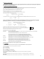
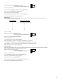
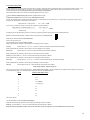
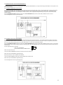
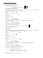
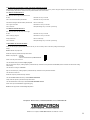
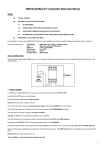
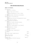
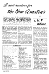
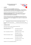
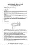
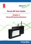
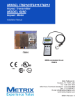
MINIFLOW2-MCU-D™ Flowmeter Driver User Manual
INDEX
1.0
INITIAL TESTING
2.0
SETTING UP FOR YOUR APPLICATION
3.0
2.1
SETTING UP THE FLOWMETER CHARACTERISTICS
2.2
ALARM MODES
2.3
SCALING APPLICATIONS
2.4
DISPENSE CONTROL APPLICATIONS (SMARTSERVE™)
2.5
COMPLETING YOUR APPLICATION INSTALLATION
2.6
ALTERNATIVE STATUS DISPLAYS FOR YOUR APPLICATION INSTALLATION
RETURNING TO FACTORY SETTINGS
It is advisable to connect up the MINIFLOW2-MCU-D to your installation and confirm operation before any reprogramming is carried out.
The unit is factory set to:
LED display
Input
Relay
Optocoupler
flow status (0 to 1000 flowmeter pulses per second)
NPN open collector flowmeter
low flow alarm output
1 second output pulse every 2000 flowmeter input pulses.
INITIAL CONNECTIONS
Connect the DC supply and the flow sensor +ve, 0V and open collector connections to the two 4 way screw terminal blocks as shown in the diagram below:
1.0 INITIAL TESTING
Set the sensor select link to PNP if a PNP open collector flowmeter is being used.
Ensure that there is no fluid flow through the flowmeter.
Set the flow alarm potentiometer fully clockwise.
Switch on the DC power supply to the unit.
The unit will power up with a 2 second start up delay and the green STATUS LED will illuminate.
The LED will then blink (on for 25ms) every 2 seconds to indicate no fluid flow detected.
The relay will also activate to signal a low alarm condition.
Slightly open the fluid flow through the flowmeter.
The LED blink rate will increase to every 0.8 seconds indicating 0 to 20% flow detected.
Increase the fluid flow through the flowmeter until the LED changes to flash (on for 400ms) every 2 seconds indicating 20 to 40% flow detected.
Note: The red OUTPUT2 LED will flash periodically as the factory set, scaling count is reached and the optocoupler output is activated.
Slowly turn the flow alarm potentiometer anticlockwise until the relay deactivates. The LOW FLOW alarm level is set to slightly less than present flow level.
Switch off the DC power supply to the unit.
The Installation is now tested and functioning correctly.
1
2.0 SETTING UP YOUR APPLICATION
The MINIFLOW2-MCU-D provides comprehensive flow alarm, scaling and batch dispensing features over a wide range of flow and can be easily configured for your
particular application. The green STATUS LED is provided for diagnostic purposes and can be set up to indicate flow, alarm or dispensing status. Simply follow the
step by step process below to set up your application:
2.1 SETTING UP THE FLOWMETER CHARACTERISTICS
Whatever your flow application, the first step is to set up the MINIFLOW2-MCU-D with the characteristics of the flowmeter being used.
These characteristics (marked on the flowmeter or flowmeter datasheet) are in the form of:
(a) Device maximum output frequency (Hz) at full flow (CALIBRATION FACTOR)
or
(b) Pulses per litre/gallon and device maximum flow litres/gallons per minute
Form (a) can be programmed directly into the unit whilst form (b) needs converting into form (a).
Use the following formula to convert form (b) into form (a):
Device Hz
=
litres(gallons) per minute x Pulses per litre(gallon)
--------------------------------------------------------------------60
e.g. Applying the formula to a flowmeter with characteristics of 4248 pulses per litre and 15 litres per minute maximum flow would convert to:
Device Hz =
15 x 4248
--------------60
= 1062
However, if your application maximum flow will never reach the maximum flow characteristics of the flowmeter you can choose to program a more convenient
calibration factor. For example, if the maximum flow for your application is 8 litres per minute then you can program in a calibration factor for a 10 litres per
minute absolute maximum flow. Use the following formula to calculate the Hz CALIBRATION FACTOR for your application:
Application Hz
e.g.
Application Hz
=
=
Application absolute maximum flow x Device Hz
------------------------------------------------------------------------Device maximum flow
10 x 1062
-----------------15
=
708 CALIBRATION FACTOR
Programming the CALIBRATION FACTOR into the unit is quick and easy using the programming plug.
Insert the programming plug facing right, centralised (MYTIME), onto the vertical left hand 6 pin SET UP header.
Rotate the flow alarm potentiometer fully anticlockwise and switch on the power.
The LED will blink slowly to indicate ready to program
Skip setting
Rotate the potentiometer fully clockwise, then on the first flash rotate the potentiometer fully anticlockwise to skip this setting.
This can be reprogrammed later, if required.
The LED will now fast blink to indicate ready to program CALIBRATION FACTOR.
Rotate the potentiometer fully clockwise to start counting in the first digit (2 in above example).
The LED will flash quite slowly for each count. Remember digital counting starts at zero not one.
First digit
Count the flashes 0, 1 then on 2 (in the example) rotate the potentiometer fully anticlockwise to store 2
Rotate potentiometer fully clockwise to start counting in second digit (6 in above example).
Second digit
Count the flashes 0, 1, 2, 3, 4, 5 then on 6 (in the example) rotate potentiometer fully anticlockwise to store 6.
Rotate potentiometer fully clockwise to start counting in third digit (0 in above example).
Third digit
Count the flashes then on 0 (in the example) rotate potentiometer fully anticlockwise to store 0.
Rotate potentiometer fully clockwise to start counting in third digit (1 in above example).
Fourth digit
Count the flashes 0 then on 1 (in the example) rotate potentiometer fully anticlockwise to store 1
Switch off the power and remove the programming plug.
Programming complete, 1062Hz stored, now time to program in your own calibration factor.
2.2
ALARM MODES
Skip this section if you intend to use the unit for single shot or autocycle (SMARTSERVE™) dispensing applications.
The unit can be set up to provide an alarm output whenever the actual flow is:
less than (LOW ALARM)
or
greater than (HIGH ALARM)
or
within a band (INBAND) of the ALARM setpoint
or
outside a band (OUTBAND) of the ALARM setpoint.
FIRSTLY REMOVE ALL FOUR SET UP JUMPER LINKS, then choose the alarm mode most suitable for your application:
LOW ALARM
In this mode the alarm output is active (on) when the actual flow is less than the 0 – 100 potentiometer setpoint%. Already factory set.
HIGH ALARM
In this mode the alarm output is active (on) when the actual flow is greater than the 0 – 100 potentiometer setpoint%. Set up as follows:
2
Insert the programming plug - facing right
- offset, upper (STARTMODE)
- onto the vertical left hand 6 pin SET UP header.
Switch on the power to the unit.
The STATUS LED will illuminate continuously to indicate High Alarm set.
Switch off the power and remove the programming plug.
Repeat the procedure to return to Low Alarm.
The STATUS LED will blink on continuously to indicate Low Alarm reset.
Switch off the power and remove the programming plug.
INBAND ALARM
In this mode the alarm output is active (on) when the actual flow is within a preset % band directly below the potentiometer setpoint%.
Choose your preset % band from the table below:
BANDSETNUMBER
PERCENTAGE FLOW BAND
0
Unit set to high/low alarm operation
1
10
2
20
3
30
4
40
5
50
And set up as follows:
Insert the programming plug - facing right
- centralised (MYTIME)
- onto the vertical left hand 6 pin SET UP header.
Rotate the alarm potentiometer fully anticlockwise.
Switch on the power to the unit.
The LED will blink slowly to indicate ready to program.
Rotate potentiometer fully clockwise to start counting in BandSetNumber (e.g. 3 for 30%).
The LED will flash quite slowly for each count. Remember digital counting starts at zero not one.
Count the flashes 0, 1, 2 then on 3 (in the example) rotate potentiometer fully anticlockwise to store 3.
Switch off the power and remove the programming plug.
OUTBAND ALARM
In this mode the alarm output is active (on) when the actual flow lies outside a preset % band directly below the potentiometer setpoint%.
Set up your preset % band as per the INBAND procedure above then:
Insert the programming plug - facing right
- offset, upper (STARTMODE)
- onto the vertical left hand 6 pin SET UP header.
Switch on the power to the unit.
The LED will illuminate continuously to indicate Outband Alarm set.
Switch off the power and remove the programming plug.
Repeat the procedure to return to Inband Alarm.
The LED will blink on continuously to indicate Inband Alarm has been reset.
Switch off the power and remove the programming plug.
3
2.3 SCALING APPLICATIONS
In these applications the unit also scales the flowmeter pulses to provide an output pulse after a predetermined number of input pulses (SCALING FACTOR). It can
be used to provide a per litre/per gallon etc. pulse train. The characteristics of the flowmeter, together with the output pulse train dimensions can be used to
calculate the SCALING FACTOR. Skip this section if you are not using the scaling feature.
These characteristics (marked on the flowmeter or flowmeter datasheet) are in the form of:
(a) Device maximum output frequency (Hz) at full flow (CALIBRATION FACTOR)
or
(b) Pulses per litre/gallon and device maximum flow litres/gallons per minute
Form (b) can be directly used to calculate the SCALING FACTOR e.g. The SCALING FACTOR required to give an output pulse every gallon (4.55 litres), using a
flowmeter with characteristics of 4248 pulses per litre would be:
Output pulse train x pulses per litre
=
4.55 x 4248 = 19328
For Form (a) e.g. 1062Hz max frequency at 15 litres the SCALING FACTOR calculation is:
Output pulse train x Maximum frequency x 60
-------------------------------------------------------------- =
Maximum flow
4.55 x 1062 x 60
----------------------- = 19328
15
Programming the five digit SCALING FACTOR is very similar to programming (lowest to highest) the flowmeter CALIBRATION factor:
Insert the red SCALING shorting plug, centralised onto the vertical left hand 6 pin SET UP header.
Rotate the flow alarm potentiometer fully anticlockwise.
Switch on the power to the unit.
The LED will blink slowly to indicate ready to program.
Rotate potentiometer fully clockwise to start counting in the first digit (8 in above example).
First digit
Count the flashes 0, 1, 2, 3, 4, 5, 6, 7 then on 8 rotate the potentiometer fully anticlockwise to store 8.
Rotate potentiometer fully clockwise to start counting in the second digit (2 in above example).
Second digit
Count the flashes 0, 1 then on 2 rotate potentiometer fully anticlockwise to store 2.
Rotate potentiometer fully clockwise to start counting in the third digit (3 in above example).
Third digit Count the flashes 0, 1, 2 then on 3 rotate potentiometer fully anticlockwise to store 3.
Rotate potentiometer fully clockwise to start counting in the fourth digit (9 in above example).
Fourth digit
Count the flashes 0, 1, 2, 3, 4, 5, 6, 7, 8 then on 9 rotate potentiometer fully anticlockwise to store 9.
Rotate potentiometer fully clockwise to start counting in the fifth digit (1 in above example).
Fifth digit
Count the flashes 0 then on 1 rotate potentiometer fully anticlockwise to store 1.
Programming complete, 19328 scaling stored.
The next step is to set up the scaling output pulse time. This is factory set to 1 second. If this time is suitable for your application switch off the power and remove
the SCALING shorting plug. If not, select the required output pulse time from the digit 6 table below:
DIGIT 6
OUTPUT PULSE TIME (seconds)
0
0.1
1
0.25
2
0.50
3
0.75 example
4
1.0 (factory set)
5
2.0
6
3.0
7
4.0
8
5.0
9
6.0
and set up as follows:
The LED will fast blink to indicate ready to program digit 6.
Rotate the potentiometer fully clockwise to start counting in the sixth digit (3 in above example).
Sixth digit Count the flashes 0, 1, 2 then on 3 rotate potentiometer fully anticlockwise to store 3.
Output pulse time programming complete, 0.75 seconds pulse time stored, now program in your own calibration factor and pulse time
4
2.4 DISPENSE CONTROL APPLICATIONS (SMARTSERVE™)
The MINIFLOW2-MCU-D contains two versatile dispense control applications (SMARTSERVE™), a single shot manually operated dispense control system, and an
autocycle control system.
2.4.1 SETTING UP SINGLE SHOT APPLICATIONS
In this mode the application controls the dispense valve and the DC power to the manual start switch circuitry. The manual start switch circuitry directly energises
the dispense valve to initiate flow. The controller then energises the dispense valve and de-energises the manual start switch circuitry. The dispense valve is
automatically de-energised when the required dispense volume is reached. After a programmed post dispense delay, the DC power to the manual start switch
circuitry is restored.
Set up the DISPENSE VOLUME (SCALING FACTOR) and the POST DISPENSE DELAY (OUTPUT PULSE TIME) as detailed in section 2.3 above.
The circuit diagram below shows a typical arrangement.
2.4.2 SETTING UP AUTOCYCLE APPLICATIONS
In this mode the application controls both the dispense valve and the liquid container transport mechanism. The controller energises the dispense valve until the
required dispense volume is reached. Then, after a 75ms delay, the controller energises the container shift mechanism circuitry for a programmed post dispense
time to move out the filled container and move in the next empty container. The cycle is then automatically repeated.
Set up the DISPENSE VOLUME (SCALING FACTOR) and the POST DISPENSE DELAY (OUTPUT PULSE TIME) as detailed in section 2.3 above. The container
shift mechanism circuitry should be arranged to initiate on the leading edge of the POST DISPENSE DELAY pulse and automatically terminate/complete before the
end of this pulse.
Insert the programming plug - facing right
- offset, upper (STARTMODE)
- onto the vertical left hand 6 pin SET UP header.
Switch on the power to the unit.
The STATUS LED will illuminate continuously to indicate AUTOCYCLE operation set.
Switch off the power and remove the programming plug.
Repeat the procedure to return to SINGLE SHOT operation.
The STATUS LED will blink on continuously to indicate SINGLE SHOT operation reset.
Switch off the power and remove the programming plug.
The circuit diagram below shows a typical arrangement.
5
2.5 COMPLETING YOUR APPLICATION INSTALLATION
The unit is now ready for final set up and installation testing:
1
Check your final calibration factor and alarm band set up.
Insert the programming plug - facing right
- centralised (MYTIME)
- onto the vertical left hand 6 pin SET UP header.
Rotate the flow alarm potentiometer fully clockwise.
Switch on the power to the unit and wait 3 seconds.
The unit will automatically count out each of the four stored digits (lowest first) on the LED with a delay of 3 seconds between each digit. Remember
digital counting starts at zero not one. So in the example (1062 stored):
First digit
Count the flashes 0, 1 & 2
Wait three seconds
Second digit
Count the flashes 0, 1, 2, 3, 4, 5 & 6
Wait three seconds
Third digit Count the flashes 0
Wait three seconds
Fourth digit
Count the flashes 0 & 1, done.
Now rotate the flow alarm potentiometer fully anticlockwise.
The unit will automatically count out the BandSetNumber on the LED. Remember digital counting starts at zero not one.
So in the above example (3 stored):
BandSet digit
Count the flashes 0, 1, 2 & 3, done.
Switch off the power to the unit and remove the programming plug.
2
Check your final scaling factor and output pulse time set up:
Insert the red SCALING shorting plug, centralised onto the vertical left hand 6 pin SET UP header.
Rotate the flow alarm potentiometer fully clockwise.
Switch on the power to the unit.
Wait three seconds
The unit will automatically count out each of the five stored digits (lowest first) on the LED with a delay of 3 seconds between each digit. Remember
digital counting starts at zero not one. So in the previous example (19328 stored):
First digit
Count the flashes 0, 1, 2, 3, 4, 5, 6, 7 & 8
Wait three seconds
Second digit
Count the flashes 0, 1 & 2
Wait three seconds
Third digit Count the flashes 0, 1, 2 & 3
Wait three seconds
Fourth digit
Count the flashes 0, 1, 2, 3, 4, 5, 6, 7, 8 & 9
Wait three seconds
Fifth digit
Count the flashes 0 & 1, done.
Now rotate the flow alarm potentiometer fully anticlockwise.
The unit will automatically count out the PulseTimeNumber on the LED. Remember digital counting starts at zero not one.
So in the above example (3 stored):
PulseTime digit
Count the flashes 0, 1, 2 & 3, done.
Switch off the power to the unit and remove the programming plug.
3
Set up the T range:
T1 Display flow - T2 jumper link in left, T3 jumper link in left.
4
Select sensor type:
NPN jumper link for NPN open collector sensor.
or
PNP jumper link for PNP open collector sensor.
5
Select alarm output:
OUTPUT jumper link in left (relay alarm, optocoupler scaling/dispense)
or
OUTPUT jumper link out right (optocoupler alarm, relay scaling/dispense).
6
DIN rail mount unit.
7
Install the flow sensor and the power, relay and optocoupler connections.
6
8
Set the setpoint% potentiometer to your application ALARM level (e.g. 75%).
(Note if a 30% flow band has been programmed the alarm band will be from 75 – 30 = 45 to 75%).
9
Switch on the unit and wait 5 seconds.
10
Check that the STATUS LED is blinking slowly (indicating no flow).
11
Check that the appropriate alarm output state is correct according to your set up:
- on, LOW ALARM
- off, HIGH ALARM
- off, INBAND ALARM
- on, OUTBAND ALARM.
12
Switch on the normal flow for the application (e.g. 50%).
13
Recheck that the status LED state is correct for the application:
0 to 20% flow
LED blinks on every 0.8 seconds
20 to 40% flow
LED flashes on every 2 seconds
e.g. 40 to 60% flow
LED flashes on every 0.8 seconds
60 to 80% flow
LED blinks off every 0.8 seconds
80 to 100% flow
LED on continuously
>100% flow
LED triple flashing every 4 seconds cycle warning.
14
Check that the alarm output state in this normal flow condition is correct according to your set up.
15
Finely adjust the setpoint% setting, if necessary, to achieve your application ALARM level.
16
If possible, adjust the flow (over the range of flow in your application), using the Status LED indication, to check each ALARM state.
17
And finally if you wish to protect your set up against unauthorised adjustment:
Switch off the power to the unit.
Temporarily remove all SET UP jumper links.
Insert the programming plug - facing right
- offset, lower (LOCKPOT)
- onto the vertical left hand 6 pin SET UP header.
Switch on the power to the unit.
The LED will illuminate continuously to indicate setpoint% setting is now locked.
Switch off the power and remove the programming plug.
Repeat the procedure, if required, to unlock the potentiometer.
The LED will flash every two seconds to indicate the potentiometer is now unlocked.
Switch off the power and remove the programming plug.
Replace all jumper links into their previous positions.
18
SMARTSERVE applications only:
Select control outputs - OUTPUT jumper link in left (relay dispense valve, optocoupler container shift controller)
or
- OUTPUT jumper link out right (optocoupler dispense valve, relay container shift controller).
Set T4 Display SMARTSERVE - T2 jumper link out right
- T3 jumper link out right
19
Ready to dispense
LED blinks on every 2 seconds
Dispensing
LED flashes on every 0.8 seconds
Dispensing complete
LED on continuously.
Record your final set up details on the configuration label on the side of the unit:
Installation is now complete.
7
2.6 ALTERNATIVE STATUS DISPLAYS FOR YOUR APPLICATION INSTALLATION
After you have completed and tested your application (unless set to T4 SMARTSERVE) you may wish to change the diagnostic status display indication. The factory
set status display T1 provides a continuous and very useful indication of the current flow%.
2.6.1 DISPLAY ALARM STATUS T2
Set - T2 jumper link out right, T3 jumper link in left.
No flow
LED blinks on every 2 seconds
Flow < lower band flow/alarm potentiometer
LED blinks on every 0.8 seconds
Flow within lower/higher band flow/alarm potentiometer
LED on continuously
Flow > higher band flow
LED flashes on every 0.8 seconds
Flow >100% flow
LED triple flashing every 4 seconds cycle warning.
2.6.2 DISPLAY SCALING STATUS T3
Set - T2 jumper link in left, T3 jumper link out right.
No flow
LED blinks on every 2 seconds
Pulse counting in progress
LED flashes on every 0.8 seconds
Output pulse active
LED on continuously
Flow >100% flow
LED triple flashing every 4 seconds cycle warning.
3.0 RETURNING TO FACTORY SETTINGS
When you start using the programmable features in the unit you can if necessary return to the factory settings and start again.
Simply:
Remove all SET UP jumper links.
Rotate the setpoint% potentiometer fully anticlockwise.
Insert a red jumper link - vertically
- centralised
- onto the vertical left hand 6 pin SET UP header.
Switch on the the power to the unit.
The LED will blink slowly to indicate ready to program.
Skip over the first five steps by rotating setpoint% potentiometer fully clockwise then fully anticlockwise five times (wait for first flash each time before rotating
anticlockwise).
The LED will now change to a fast blink.
Skip over the sixth step by rotating setpoint% potentiometer fully clockwise then fully anticlockwise once.
The LED will now switch off.
Rotate the setpoint% potentiometer fully clockwise.
The LED will flash on/off continuously to indicate RESET ACTIVATED.
Finally rotate the setpoint% potentiometer fully anticlockwise.
The LED will illuminate continuously to indicate FACTORY SETTINGS restored.
Switch off the power and remove the programming plug.
Restore all four jumper links to their factory set positions.
Tempatron: Eltime House, Hall Road, Maldon, Essex, CM9 4NF UK.
Tempatron Industrial Controls is a division of Eltime Ltd.
© Eltime Ltd. Tempatron MINIFLOW2-MCU-D User Manual 01/2014
8