1
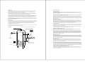
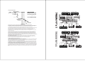
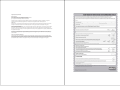
INTRODUCTION
The corrosion resistant AquaPod Unvented cylinder is made from Duplex Stainless Steel. It is highly insulated with
environmentally friendly foam enclosed in a rust resistant white steel case.
It is available in Direct, and Indirect versions in a family of 7 sizes from 90 – 300 litres in Twin Coil and Indirect. Direct Eco
units are available in 5 sizes from 150 - 300 litres . There is also a range of slimstyle units from 60 - 210 Litres again in Direct
and Indirect versions.
To help ensure compliance with the relevant Water and Building Regulations all AquaPod units are supplied complete with the
necessary safety and control devices needed to connect to the cold water mains. In order to ensure high flowrate performance
with minimum pressure drop even in lower pressure areas , pre-adjusted. High quality controls have been selected.
AquaPod is approved to demonstrate compliance with Water Regulations and Building Regulations G3 & Part L.
STORAGE PRIOR TO INSTALLATION
AquaPod should be stored upright in a dry area and kept in its original packaging until immediately prior to installation.
INSTALLATION PREREQUISITES
This Cylinder should only be installed by a competent installer holding their G3 unvented qualification. The installation of this
product is also notifiable under the national building regulations.
ONCE COMPLETED THIS INSTRUCTION MANUAL IN ITS ENTIRETY SHOULD BE LEFT WITH THE HOME OWNER.
WHAT IS BENCHMARK?
Benchmark places responsibilities on both manufacturers and installers. The purpose is to ensure that customers are
provided with the correct equipment for their needs, that it is installed, commissioned and serviced in accordance with the
manufacturer’s instructions by competent persons and that it meets the requirements of the appropriate Building Regulations.
The Benchmark Checklist can be used to demonstrate compliance with Building Regulations and should be provided to the
customer for future reference.
Installers are required to carry out installation, commissioning and servicing work in accordance with the Benchmark Code of
Practice which is available from the Heating and Hotwater Industry Council who manage and promote the scheme. Visit
www.centralheating.co.uk
Equipment Supplied With Cylinder
Cold Water Inlet Set
15 x 22mm Tundish
Temperature & Pressure Relief Valve
Expansion Vessel
Expansion Vessel Bracket
500mm Expansion Hose
Immersion Heater(s) - Dependant on size & configuration
Instructional Manual
Installation Manual
Issue 1
Benchmark Log Book - Found at the rear of this manual
a
WATER SUPPLY
AquaPod is capable of delivering over 50 litres per minute when connected to a suitable mains supply. The high quality
inlet control set with its 3 bar operating pressure has been designed to make the most of what is available however the
performance of any Unvented system is only as good as the water supply.
In unvented systems both hot and cold services are supplied simultaneously from the mains so the maximum possible
on-site water demand must be assessed and the water supply should be tested to ensure it can meet these requirements. If
necessary consult the local water supplier regarding the likely pressure and flow rate availability.
It is important that site pressure readings are taken under dynamic flow conditions, high pressures under zero flow conditions
are not necessarily indicative of satisfactory performance. A minimum of 1.5 bar at 20 l/m flow should be available. Where
mains inlet pressures are likely to exceed 16 bar then an additional upstream pressure reducing device should be fitted.
A minimum of 22mm supply pipe-work should ideally be provided and existing 1/2” (15mm) cold mains pipe-work may need
to be upgraded. Hard water treatment should be considered in areas where content it greater than 200ppm, if required adjust
cylinder temperature to below 60 degrees.
SITING THE UNIT
AquaPod can be positioned more or less anywhere in the dwelling but it should be remembered that for every 1 meter that an
outlet is above the AquaPod, the pressure will be reduced by 0.1 bar. If siting outside the heated envelope of the dwelling such
as in a garage or outbuilding then frost protection should be provided and exposed pipework should be insulated.
AquaPod must be supported on a flat base capable of supporting the weight of the cylinder when full. The minimum
recommended cupboard size is 650mm square.
GENERAL INSTALLATION
COLD MAINS PIPEWORK
Run the cold main through the building to the place where the AquaPod is to be installed. Take care not to run the cold
pipe near hot water or heating pipe work so that the heat pick up is minimized. Identify the cold water supply pipe and fit an
isolating valve (not supplied).
A 22mm BS1010 stopcock can typically be used but a 22mm quarter turn full bore valve would be better as it does not restrict
the flow as much. Do not use “screwdriver slot” or similar valves.
Make the connection to the cold feed of the cylinder and incorporate a drain valve. Position the inlet control just ABOVE the
Temperature & Pressure Relief Valve (TPRV) mounted on the side of the cylinder. This ensures that the cylinder does not
have to be drained down in order to service the inlet control set. Ensure that the arrow points in the direction of the water flow.
Select a suitable position for the expansion vessel. Mount it to the wall using the bracket provided. Use the hose to connect to
the inlet control group.
BALANCED COLD CONNECTION
If there are to be showers, bidets or monobloc taps in the installation then a balanced cold supply is necessary. There is a
22mm balanced connection on the inlet control set. An alternative method is to split the inlet control set on to two parts. Site
the pressure reducing valve immediately after the incomming cold mains stopcock (typically under the kitchen sink). All outlets
in the house will be at 3 bar and thus automatically balanced. The expansion relief valve section must still be mounted just
above the TPRV on the cylinder. A 3/4”F-22mm compression adaptor will be needed (not supplied).
It’s important that consideration is given to access for maintenance of the valves. The immersion heaters are 375 mm long and
access space should be provided for possible future replacement
HOT WATER PIPEWORK
Run the first part of the hot water distribution pipework in 22mm. This can be reduced to 15mm and 10mm as appropriate for
the type of tap etc. Your aim should be to reduce the volume of the hot draw off pipework to a practical minimum so that the
time taken for the hot water is as quick as possible.
SCHEMATIC
Do not use monobloc mixer tap or showers if the balanced cold connection is not provided. The unit will back pressurise the
unit and result in discharge. Ensure that the top of the vessel is accessible for servicing.
* Do not fit shut off valve between Cylinder and Expansion Valve
Hot Outlet
PRIMARY COIL CONNECTIONS (Indirect Only)
Compression connections are provided for the primary circuit which must be positively pumped. Primary flow and return
connections are interchangeable to suit site conditions without affecting reheat times.
Expansion Vessel
With Wall Bracket
Temperature
& Pressure
Relief Valve
Non Return
Valve
Pump
Sealed or vented primary circuits can be used, to comply with normal installation practice the primary pressure should not
exceed 3 bar although the coil in Stelfow is suitable for up to 7 bar if required. The boiler may be Gas, Electric, Oil etc but
must be under effective thermostatic control. Uncontrolled heat sources such as some AGA’s, back boilers, solid fuel stoves,
etc may not be suitable please contact us for guidance. The two port zone valve should be installed into the primary flow
pipework leading to the coil flow inlet. The direction of flow arrow should be towards the primary flow connection. On twin coil
cylinders an extra thermostat boss is provided.
Expansion Relief
Valve
*
Tundish
Non Return
Valve
Isolating
Valve
Cold
Main
Secondary Return
Pressure
Reducing
Valve
2 Port
Valve
Boiler Flow
Dual
Stat
Drain Via
Cold Inlet
Balanced Cold Connection
Boiler Return
SECONDARY CIRCULATION
Where secondary circulation is required a circulator suitable for potable water should be used in conjunction with a non return
valve to prevent backflow. it may be necessary to incorporate an extra expansion vessel into the circuit to accommodate the
increased system water volume in larger secondary circulation systems. Where off peak electrical tariffs are being used then
secondary circulation should be avoided. A secondary return boss is fitted as standard on 210, 250 & 300L. On smaller sizes
tee into the cold feed pipe above the drain.
IMMERSION HEATERS
As a requirement of Building regulations the AquaPod immersion heaters are fitted with thermal cut-out in addition to the
normal control thermostat. To help ensure correct replacement the immersion heaters have a special 13/4“ thread. They are
of a low noise Incoloy construction and rated at 3 kW at 240 V. Replacement immersion heaters should be purchased via
ourselves otherwise your guarantee may be affected.
The ‘O’ring on the head of the immersion heater should be correctly positioned and lubricated before fitting . Screw in handtight until almost then gently tighten as the ‘O’ rings will seal easily. The electrical supply to each immersion heaters must be
fused at 13A via a double pole isolating switch to BS 3456. The cable must be 2.5mm2 heat resistant (85°C HOFR) sheathed
flex complying to BS 6141:1981 Table 8. Do not operate the immersion heater/s until the unit is full of water. If any sterilisation
liquid is in the cylinder do not operate the immersion heater/s as this will cause premature failure. Electric to be supplied by a
fused supply compliant with local regulations, and fitted by a qualified Part P Electrician.
ENERGY CUT OUT AND CYLINDER THERMOSTAT (Indirect Only)
As a requirement of Building regulations the AquaPod units are fitted with a thermal cut-out in addition to the normal control
thermostat. This unit should be fitted to the dedicated boss on the cylinder and wired to the two port valve controlling the
primary flow.(see wiring diagram).
DISCHARGE ARRANGEMENT
Zone Valve - Heating
Room Stat
1
2
L
N
It is important that any discharge water does not collect in this pipe-work and can run freely to the tundish.
The Tundish should be mounted in a vertical and visible position located in the same space as the unvented hot water storage
system and be fitted as close as possible and within 500mm of the safety device e.g. the temperature relief valve. The
discharge pipe-work from the tundish must be routed in accordance with Part G3 of the Building Regulations.
L
N
E
E
HT
ON
DHW
ON
4
Cylinder Stat
E
6
7
8
SL
L
N
E
Room Stat
1
L
2
N
N
1
N
E
E
HT
ON
DHW
ON
N
E
Pump
2 Port Valve - DHW
Green/
Yellow
2
4
Green/
Yellow
Blue Grey Oran.
Brown
C
L
E
10
L
Energy Cut Out
3
Time Control
2
Boiler
Blue Grey Oran.
White
C
5
3 Port Valve
Y PLAN WIRING
Examples of acceptable discharge arrangements are:
1. Ideally below the fixed grating and above the water seal in a trapped gulley.
2. Downward discharges at a low level; i.e. up to 100mm above external surfaces such as car parks, hard standings, grassed
areas etc. are acceptable providing that where children play or otherwise come into contact with discharges, a wire cage or
similar guard is positioned to prevent contact whilst maintaining visibility.
3. Discharges at a high level; e.g. in to metal hopper and metal down pipe with the end of the discharge pipe clearly visible
(tundish visible or not) or onto a roof capable of withstanding high temperature discharges of water and 3m from any plastic
guttering systems that would collect such discharges (tundish available).
4. Where a single pipe serves a number of discharges, such as in blocks of flats, the number served should be limited to not
more than 6 systems so that any installation can be traced reasonably easily. The single common discharge pipe should be
at least one pipe size larger than the largest individual discharge pipe to be connected. If unvented hot water storage systems
are installed where discharges from safety devices may not be apparent i.e. in dwellings occupied by blind, infirm or disabled
people, consideration should be given to the installation of an electronically operated device to warn when discharge takes
place.
2
Time Control
The discharge pipe from the tundish should terminate in a safe place where there is no risk to persons in the vicinity of the
discharge, be of metal and:
a) Be at least one pipe size larger than the nominal outlet size of the safety device unless its total equivalent hydraulic
resistance exceeds that of a straight pipe 9m long i.e. discharge pipes between 9m and 18m equivalent resistance length
should be at least two sizes larger than the nominal outlet size of the safety device, between 18 and 27m at least 3 sizes
larger, and so on. Bends must be taken into account in calculating the flow resistance. An alternative approach for sizing
discharge pipes would be to follow BS6700 Specification for design installation, testing and maintenance of services supplying
water for domestic use within buildings and their curtilages.
b) Have a vertical section of pipe at least 300mm long, below the tundish before any elbows or bends in the pipework.
c) Be installed with a continuous fall.
d) It is preferable for the discharge to be visible at both the tundish and the final point of discharge but where this is not
possible or practically difficult there should be clear visibility at one or other of these locations.
C
Green/
Yellow
Blue Grey Oran.
Brown
Energy Cut Out
3
General guidance is provide by the above diagram extracted from the G3 Building Regulation Guidance.
This guidance is available as a free of charge download of the G3 Approved Document from www.planningportal.gov.uk.
The discharge from both the Temperature relief and expansion relief valves can be joined together via a 15mm end feed Tee.
Zone Valve - DHW
Green/
Yellow
Blue Grey Oran.
Brown
Cylinder Stat
E
C
5
6
7
8
SL
L
N
E
Boiler
2
N
1
E
10
L
N
Pump
E
COMMISSIONING SERVICING
FILLING
Check all connections for water tightness including any factory made connections such as the immersion heater and the
temperature and pressure relief valve. The pressure in the expansion vessel should be checked to ensure it is 3 bar (45PSI).
The valve is of the car tyre (Schrader) type.
The hot tap furthest away from the AquaPod should be opened before filling the system to let air out.
The system should be flushed before use. The remaining taps should be opened in turn to expel air.
DIRECT UNITS
The system must be fully filled and flushed before switching on the power to the immersion heaters and allowing the unit to
heat up. The immersion heater is supplied preset at 55°C. Turning fully to + sets to approx 65°C.
INDIRECT UNITS
Ensure the lever on the two port valve is set to the filling position and use the boiler manufacturers commissioning instructions
to fill the primary circuit. When full release the lever. Switch the programmer to Domestic Hot water (DHW) and allow the unit
to start to heat. Adjust the dial of the dual thermostat to between 55°C and 65°C as required.
STORAGE TEMPERATURE
A storage temperature of 60-65°C is normal for both direct and indirect AquaPods . In hard water areas consideration should
be given to reducing this to 55-60°C. In many healthcare applications the guidance on Legionella control and safe water
delivery temperatures will require storing the water at 60-65°C, distributing at 50-55°C and using thermostatic mixing valves to
control the final temperature. For details consult the NHS estates guidance on safe hot water temperatures.
SAFETY VALVE CHECKS
Any water coming from either the expansion relief valve or the temperature / pressure relief valve during heat up is indicative
of a problem which needs to be identified and rectified. The temperature relief and expansion relief valves should be fully
opened, one at a time then both together allowing as much water as possible to flow through the tundish. Check that your
discharge pipework is free from debris and is carrying the water away without spillage over the tundish and release the valves
and check that they reseat properly.
GENERAL
Servicing should only be carried out by competent installers and any spare parts used must be purchased from RM Cylinders.
NEVER bypass any safety devices or operate the unit without them fully operational.
DRAINING
Isolate from the electrical supply to prevent the immersion heaters burning out. Isolate the unit from the cold mains. Attach
a hose to the draining tap ensuring it reaches to a level below the unit (This will ensure an efficient syphon is set up and the
maximum amount of water is drained from the unit). Open the hot tap closest to the unit and open the draining tap.
GUARANTEE
The AquaPod stainless steel vessel carries a 25 year guarantee against faulty materials or manufacture provided that:
•
•
•
•
•
•
•
•
•
•
It has been correctly installed as per this document and all the relevant standards, regulations and codes of practice in
force at the time.
It has not been modified in any way, other than by RM Cylinders.
It has not been misused, tampered with or subjected to neglect.
It has only been used for the storage of potable water.
It has not been subjected to frost damage.
The unit has been serviced annually.
The benchmark service record has been filled in after each annual service.
The guarantee period starts from the date of purchase and no registration is required.
The extended guarantee is not transferable, and rests with the original householder.
The system is fed from a public water supply.
Please note that invoices for servicing may be requested to prove that the unit has been serviced annually. All the components
fitted to / or supplied with the AquaPod carry a 2 year guarantee.
EXCLUSIONS –THE GUARANTEE DOES NOT COVER
The effects of scale build up. Any labour charges associated with replacing the unit or its parts. Any consequential losses
caused by the failure or malfunction of the unit.
GUIDANCE IN THE EVENT OF A PROBLEM
If you have a problem in the first year contact the plumber who fitted the unit. Thereafter contact the plumber who carries
out the annual servicing for you. If your AquaPod develops a leak we will supply you with a new one. We ask for an up-front
payment to prevent fraud. We will require the original unit to be returned to us for inspection along with a copy of your service
record and commissioning checksheet. If it is confirmed that it has failed within the terms of the warranty your upfront payment
will be refunded. If a component part fails within the two year guarantee period we will send you a new one again with an
upfront charge. Credit card details may be taken to prevent fraud. We ask you to post the faulty part back to us within one
month by recorded delivery. Once the part has been tested and proven faulty a refund will be issued.
USER INSTRUCTIONS
Your stainless system is automatic in normal use and requires only annual servicing. You should employ an competent
installer to perform the annual servicing. Normally this is timed to coincide with the annual boiler service.
IF WATER IS FLOWING FROM THE SAFETY VALVES THROUGH THE TUNDISH THIS INDICATES A FAULT CONDITION
AND ACTION IS NEEDED.
If this water is hot turn the boiler and / or the immersion heater off. Do not turn off the water until the discharge runs cool. The
discharge may also stop.
CALL A COMPETENT PLUMBER OUT TO SERVICE THE UNIT.
WARNING: WATER DRAINED OFF MAY BE VERY HOT!
Tell them you have a fault on an unvented cylinder. We stock all the spare parts they may need.
ANNUAL SERVICING
A competent installer should carry out the following checks on an annual basis, ideally at the same time as the annual boiler
service.
1) The expansion relief valve on the inlet control set should be eased open allowing water to flow for 5 seconds. The valve
should then be closed making sure it resets correctly. Repeat this procedure with the pressure / temperature relief valve.
Always insure that the discharge pipework is allowing the water to drain away adequately. If not check for blockages etc. and
clear.
WARNING: THE WATER DISCHARGED MAY BE VERY HOT!
2) Ensure that any immersion heaters that are fitted are working correctly and that they are controlling the water at a
temperature of between 55°C and 65°C.
3) Make sure the pressure in the expansion vessel is charged to 3 bar. Turn off the water supply to the unit and open a hot
tap first. The valve on the expansion vessel is a Schrader (standard car tyre) type. Air or CO2 can be used to repressurise the
expansion vessel.
4) Remove the head on the inlet control set by unscrewing, and clean the mesh filter within.
5) The benchmark service record supplied within this manual should be updated at each service.
YOUR GUARANTEE MAY BE VOID WITHOUT PROOF OF ANNUAL SERVICING.
THE COMMISSIONING CERTIFICATE SUPPLIED AT THE REAR OF THIS MANUAL SHOULD ALSO BE COMPLETED.
AquaPod Unvented Indirect
Twin Coil Solar
Indirect twin coil units can be installed in two separate formats:
a) In a solar powered system with a fossil fuel boiler.
b) In a system with two independent fossil fuel boilers.
With either format it is essential the overall installation meets all current legislation including, in particular, the high limit
isolation requirements of Building Regulation G3. This document is designed to assist in achieving this aim.
Upper Coil
The upper coil is connected to the fossil fuel boiler as per the instructions for the AquaPod single coil model with the control
and high limit thermostat inserted into the middle stat pocket. The wiring requirements are as depicted in this guide.
Lower Coil: Solar Installation
In a solar powered system the lower coil is connected to the solar heat source. Either primary coil connection may be utilised
as the flow or return. The solar cylinder sensor, supplied as part of the solar controls, inserts into the lower stat pocket. It is
necessary to mount the solar pump in the return pipework with the two port valve (supplied with the cylinder) installed between
the cylinder and the pump.
This valve is of the powered open, sprung closed design and is wired through the high limit stat which inserts into the upper
stat pocket. Two wiring options for high limit isolation are provided in this guide. The control thermostat is not required in a
solar installation.
Lower Coil: Two Boiler Installation
Where the lower coil is to be used with a fossil fuel boiler, the pipework requirements are as per that of a Stainless Indirect
single coil cylinder described earlier in this book. However the electrical requirements mean the control thermostat inserts into
the lower tank stat pocket to control the boiler input and the limit stat into the upper tank stat pocket. The two port valve may
be installed into either the flow or return pipework. Wiring of the controls are as per the wiring diagram in this guide.
Essential Cylinder Information
Maximum water supply pressure - 16 Bar
Immersed electric element rating - 3kW
Operating pressure - 3 Bar
Expansion vessel charge pressure - 3 Bar
Expansion valve setting - 6 Bar
Set opening pressure of combined T&P valve - 7 Bar
Storage capacity - See cylinder info table
Mass of unit - See cylinder data table
Immersion heater length - 14”
Maximum primary pressure (indirects only) - 3 Bar
Cylinder Data Table
Capacity (Litres)
Weight (Kg)(Empty)
Direct
90
21
Indirect
88
23
Direct
120
26
Indirect
118
30
Direct
150
33
Indirect
148
38
Direct Solar
148
38
Solar Twin
147
40
Direct
180
38
Indirect
178
42
Direct Solar
178
42
Solar Twin
177
45
Direct
210
41
Indirect
208
45
Direct Solar
208
45
Solar Twin
207
48
Direct
250
46
Indirect
248
51
Direct Solar
248
51
Solar Twin
247
53
Direct
300
55
Indirect
298
60
Direct Solar
298
60
Solar Twin
297
63
AquaPod 90
AquaPod 120
AquaPod 150
AquaPod 180
AquaPod 210
AquaPod 250
AquaPod 300
Copper Industries
Toome Business Park, 21 Hillhead Road, Toome
Co. Antrim, BT41 3SF
Tel: 028 796 59736
Fax: 028 796 50000