1
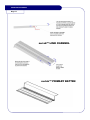
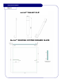
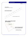
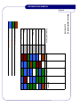
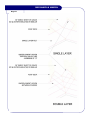
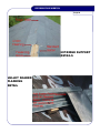
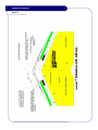
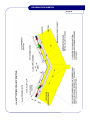
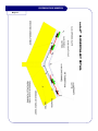
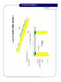
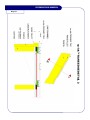
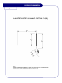
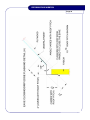
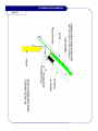
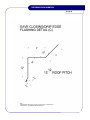
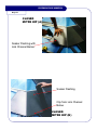
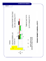
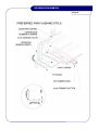
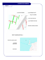
VERSION 3 — February 2004
INSTALLATION
MANUAL
Nu-lok™ USA LLC
711 South Carson Street Suite 4 Carson City Nevada 89701
Tel 1-800-94-68565 Fax 775-882-8926 Email [email protected]
www.nu-lokusa.com
INSTALLATION MANUAL
INTRODUCTION
NU-LOK™ THE ROOF
Nu-lok™ is a patented revolutionary roofing system. It
breaks the mould on traditional roof installation methods
by using a unique method of fastening slate and ceramic
slate materials.
The purpose of this manual is to assist the already skilled
operator by providing technical information necessary to
install the nu-lok™ roofing system.
The nu-lok™ fastening system, although unique in the
USA, requires only a few minutes of reading for an
already qualified roofing contractor to learn.
The basic nu-lok™ system does not vary in the method of
installation, however, some regional adjustments may be
necessary for local or regional authority approval. If you
have any questions on this or indeed on any part of the
nu-lok™ installation, please call 800-565-9244 for help or
email us with feedback on your personal suggestions to
improve the installation on [email protected].
INSTALLATION MANUAL
Page
Contents
COMPONENTS............................................................................................. Page 1
THE BASICS................................................................................................. Page 2
Roof slope, The deck weight, Underlayment, Site conditions ............. Page 2
Storage, Fasteners............................................................................ Page 3
Tools................................................................................................. Page 4
Flashings .......................................................................................... Page 4
PREPARING YOUR ROOF FOR INSTALLATION ......................................... Page 5
Inspect the surface of the plywood, Apply the underlayment .............. Page 5
INSTALLING NU-LOK™................................................................................ Page 6
Now you are ready for nu-lok™ battens............................................. Page 6
Setting out the primary batten ........................................................... Page 6
Ridge batten details .......................................................................... Page 7
Hip batten details .............................................................................. Page 8
Valley batten details - Open valley & Closed valley............................ Page 8
Fastening metal battens, Fascia batten ............................................. Page 9
LAYING SLATE............................................................................................. Page 10
Loading the roof, Link channels, Laying the roof slates...................... Page 10
Cutting in hips and valleys - Open Valley........................................... Page 11
Cutting in hips and valleys - Closed valley & Closed mitred hip.......... Page 12
Ridge top cuts................................................................................... Page 13
FLASHINGS.................................................................................................. Page 13
Flashings new construction, Rake Edge ............................................ Page 13
Drip edge/eave closing flashing, Flashing to vertical surfaces............ Page 14
Pan flashing, Vents/penetration flashing, .......................................... Page 14
Skylights and chimney flashing, Vents, Snow Guards........................ Page 15
General note..................................................................................... Page 15
NOTE TO THE INSTALLER .......................................................................... Page 16
DETAILED DIAGRAMS & PHOTOS .............................................................. Page 17
Link channel & Primary Batten .......................................................... Page 17
Fascia batten & Wire Clip.................................................................. Page 18
Valley clip & Ceramic slate................................................................ Page 19
Set-out rod & Single layer underlayment ........................................... Page 20
INSTALLATION MANUAL
Double layer underlayment class A ................................................... Page 21
Fascia batten/gutter detail ................................................................. Page 21
Metal compatibility chart.................................................................... Page 22
Single & double layer valley underlayment ........................................ Page 23
Primary batten set-out ....................................................................... Page 24
Standard batten layout detail B.......................................................... Page 24
Closed Valley.................................................................................... Page 25
Standard batten layout detail A.......................................................... Page 25
Hip/ridge support & Valley soaker flashing detail ............................... Page 26
Slate ridge detail ............................................................................... Page 27
Metal ridge detail............................................................................... Page 28
Clay ridge detail ................................................................................ Page 29
Open valley detail ............................................................................. Page 30
Closed valley detail ........................................................................... Page 31
Metal shears & roof loading photos ................................................... Page 32
Slate on link channel photo ............................................................... Page 33
Cut tile to valley detail ....................................................................... Page 33
Rake edge detail 1 ............................................................................ Page 34
Rake edge detail 2 ............................................................................ Page 35
Rake edge flashing detail 3A............................................................. Page 36
Rake edge flashing detail 3B............................................................. Page 37
Eave closing/drip edge flashing detail A ............................................ Page 38
Eave closing/drip edge flashing detail B ............................................ Page 39
Eave closing/drip edge flashing detail C ............................................ Page 40
Eave closing/drip edge flashing detail E ............................................ Page 41
Eave closing/drip edge flashing detail H ............................................ Page 42
Closed mitred hip A & B .................................................................... Page 43
Wall detail with pan flashing .............................................................. Page 44
Rake flashing detail........................................................................... Page 45
Preferred pan flashing style............................................................... Page 46
Valley detail & Vent flashing detail A ................................................. Page 47
Vent flashing detail B ........................................................................ Page 48
Chimney flashing ............................................................................. Page 49
INSTALLATION MANUAL
Page 1
COMPONENTS
Link Channel (Page 17)
Primary Batten (Page 17)
Fascia Batten (Page 18)
Wire Clip (Page 18)
Valley Clip (Page 19)
Ceramic Slate (Page 19)
nu-lok™ uses and recommends natural Vermont slate for
its quality and strength. Contact Greenstone Slate on Tel
1 800 619 4333 www.greenstoneslate.com
INSTALLATION MANUAL
Page 2
THE BASICS
ROOF SLOPE
nu-lok™ recommends a minimum roof slope of 4:12. It is possible to go lower,
however, please contact nu-lok™ technical support on 800-565-9244 to discuss prior to
installation.
THE DECK : WEIGHT
Nu-lok™ weights 5.6 lbs per sq ft with ceramic slate and between 5 — 6 lbs with natural
Vermont slate depending on the style selected. Other natural slates may weigh more.
This may vary slightly if a heavy underlayment is called for by local authorities. The
roof deck must be constructed to accept this kind of dead load. If in doubt consult an
engineer before commencing nu-lok™.
UNDERLAYMENT
Ensure the underlayment is a complete waterproof membrane capable of dispersing
any moisture at the eaves.
Wind driven rain, capillary and ice damming can cause water migration through the
joints in the slate so the integrity of the underlayment is essential and must be carefully
protected throughout the installation process.
Nu-lok™ does not specify a particular underlayment for use with the system, however,
some options are Grace Ice and Water Shield™, Tri-Flex® 30 by FlexiaCorp or
Titanium-UDL™ by InterWrap Inc. for all standard installations laid per manufacturer’s
instructions. Nu-lok™ recommends 2 layers of mineral cap sheet (40 lb D4601) laid
with a minimum 6” vertical lap and woven in valleys, with a minimum 4” turn up at all
vertical wall surfaces for all Class ‘A’ Fire Rated installations using ceramic slates.
Ensure all decks are in good condition and all damage, rot, loose or otherwise
imperfect sheets are repaired prior to commencement of nu-lok™.
SITE CONDITIONS
Do not start any work on the deck if wet of frozen conditions exist. Ensure the deck is
fully repaired and ready to accept a new roof covering.
INSTALLATION MANUAL
Page 3
STORAGE
Always store nu-lok™ slates and components in a dry clean environment. Ensure they
are not left exposed to the elements for long periods prior to their use.
Residual water trapped between the ceramic slates and left over a long period can
cause a whitening effect and is not readily removed.
The primary and fascia battens are delivered to site in bundles of 10 for ease of
handling and should be stored on an elevated surface preferably out of the weather.
The link channels and wire clips come in boxes and should be kept dry until ready for
use.
FASTENERS
Battens are best attached with a pneumatic nail gun. The length of the fastener may
vary depending on the thickness of the counter batten or shim used to elevate the nulok™ batten off the ply deck.
A minimum 2½” length 9 gauge double dipped galvanized ring shank nail driven
through the batten, shim and plywood and into the rafter below (meeting ASTM A-153
Standard) is recommended.
Ensure any fastener used is a non reactive metal with the nu-lok™ galvanized steel
batten. If you have any doubt consult the chart in this document. (See Page 22)
All underlayments must be attached per manufacturer’s requirements. Mineral cap; ¾”
corrosive resistant 12 gauge with 15/16” head roofing felt nails.
The link channels are attached by locking them into the lip of the standard/fascia batten
and as in standard application require no further fasteners. The link channel locks
under the primary batten and over the slate below holding the slate in place.
When using cedar lath as a counter batten ensure the laths are fastened above each
rafter fastening through the lath and plywood into the rafter below using a minimum 2”
galvanized nail.
Ceramic and natural slate; no nails required—stainless steel wire clips secure the nose
end of the slate.
Valley clips; galvanized ¼” pop rivet or similar non corrosive compatible metal.
INSTALLATION MANUAL
Page 4
TOOLS
The following tools are required for a nu-lok™ ceramic or natural slate installation.
•
•
•
•
•
•
•
•
•
•
•
•
•
•
•
•
All safety equipment required by OSHA and any other regulatory safety body.
Claw hammer
Tape
Pencil
Metal Shears
Caulking gun
Good quality floor tile cutter score and snap style sigma or similar quality
capable of accepting a tile up to 2’ square
Set out tool (Page 20)
Chalk Line
Felt Knife
Small Electric grinder
Extension Leads
Bevel
Screw Gun or Cordless Screwdriver
Nail Gun and Compressor
Natural Slate Cutter
FLASHINGS
All metal flashings used must be of a non reactive type with nu-lok™ galvanized metals.
If you are unsure consult the enclosed chart on Page 22.
All flashings should be installed in accordance with NRCA, WSRCA and the 1997 UBC
Chapter 15. nu-lok™ recommends a minimum 26 gauge G90 galvanized metal or
factory pre painted 26 gauge galvanized metal color matched to the slate being used.
Optional 16 oz copper may also be used.
Virtually any industry metal flashing is ok to use with nu-lok™ as long as the metal is
compatible with galvanized steel. (See Chart Page 22)
On a closed mitered hip or closed valley provide individual soaker flashings under each
row attached to the primary batten below. (See Photos Page 25 & 43)
When using cut slate as hip/ridge detail supply metal underflashing. To secure cut
pieces use a recommended metal to ceramic/stone 50 year adhesive such as ‘PL
Landscaping Block Adhesive’ and appropriate nails or screws.
INSTALLATION MANUAL
Page 5
PREPARING YOUR ROOF FOR INSTALLATION.
INSPECT THE SURFACE OF THE PLYWOOD.
Always check to ensure that no nails or other sharp objects protrude through the
surface of your plywood before applying the waterproof underlayment.
Any damage found such as: Rotting plywood, lifting/separating sheets, warping or any
other form of unsatisfactory surface, should be repaired at this time as it could lead to
an unsatisfactory final product.
Plywood is not a necessary base for nu-lok™. Primary battens may be applied directly
onto rafters at up to 3’ centers, for details contact a nu-lok™ representative.
APPLY THE UNDERLAYMENT.
Apply one layer of approved high quality underlayment to the complete deck surface,
ensuring a minimum 2” lap at all flat surface joints and 12” over hips and ridges (at the
shortest point if sheets are cut off square). Ensure at least 12” of underlayment folds
back under the horizontal surfaces from the valleys. This should go on prior to the
laying of the horizontal surfaces. It is recommended that a layer of “Grace Ice and
Water Shield™” is applied to all penetrations and valleys before any underlayment is
installed. “Grace Ice & Water Shield”, Tri-Flex 30® by FlexiaCorp or Titanium-UDL™ by
InterWrap Inc. can be used for all standard installations and for Class A fire rating;
apply two plies of 40 lb D4601 mineral cap sheet per manufacturer’s specifications.
(See Pages 20 & 21)
If local codes demand install standard drip edge at eaves. Drip edge details can
incorporate eave closing flashings (See Pages 38 — 42 inclusive).
Commence underlayment at eaves laying parallel to eaves working towards the ridge.
All underlayment should be installed per manufacturer’s requirements and relevant
codes. Interlace felt at valley sections crossing over for full coverage. (See Page 23)
Underlayment must extend a minimum 4” up all vertical wall surfaces. It is understood
the underlayment membrane shall fully waterproof the roof deck. It shall be a
weatherproof barrier capable of shedding any moisture to which it may be exposed
allowing it to escape at the eaves.
Care must be taken at all times to protect the integrity of the waterproof membrane.
INSTALLATION MANUAL
Page 6
INSTALLING NU-LOK
START WITH COUNTER BATTENS
Nu-lok uses horizontal steel battens. On a plywood application there is the danger that
any penetrating moisture could be trapped behind the horizontal battens. Therefore, to
avoid trapped moisture on a plywood deck always use a counter batten running
vertically up the roof. We recommend a cedar lath or a rubber shim. Always ensure
the lath or shim is placed above a rafter with the fasteners driven through he lath
through the plywood and into the rafter below. We recommend a min 2” galvanized
ring shank nail for best results..
SETTING OUT THE PRIMARY BATTEN
Measure 12⅜” up from the back of the fascia at one end and drive a 1½” nail into the
roof leaving ⅜th of an inch protruding. Then go to the other end and to the same thing.
(See Page 24.) Now string a chalk line between the two nails. Check the
measurements are similar in several places along the line, between the line and back
of the fascia. If the measurements are fairly consistent ping the chalk line. If there is a
large difference you may need to make adjustments to the line or the entire roof may
be out of square. If this is the case the fascia may need to be packed out or cut back.
It is important this front line is straight and square, the whole roof face is set out from
this line.
Note: The first batten measurement may vary depending on the desired overhang —
check overhang required and adjust 12⅜” measurement accordingly.
Do not leave the nails too far out as they will sit above the battens and clash with the
slates. You will only have to bang them in later. If they go unnoticed and you walk on
a slate with a nail too high below, it can cause slate breakages.
INSTALLATION MANUAL
Page 7
Now that the fascia line is straight, place the Setout Rod (See Page 20) over the first
nail. Put the nail through the first hole in the rod, (with the rod lying vertically up the
roof) and put a nail in every hole in the rod. Do this all the way to the ridge line. Then
repeat this process at the other end of the roof. Now use these nails to ping parallel
horizontal lines all the way to the ridge.
The last row of battens may or may not be a standard 12⅛” centre. It’s ok - the last
batten should be positioned to suit the type of ridge cap being applied. (See Page 24)
3” is good for metal ridge cap and cut slate, however, 2” is better suited for clay. nulok™ recommends a hip/ridge mockup is done to ensure alterations are not required
later. The last row of link channels to the ridge are simply cut to suit the required size.
Fasten a nu-lok™ primary batten to align with every chalk line (at 12⅛” centers)
ensuring the nails are driven through the packer batten and plywood and into the rafter
below, all the way to the ridge and out to the edge of the hip on each side. (See Pages
24 & 25) Repeat this procedure all the way around the roof until all battens are
complete.
Note: The nu-lok™ system works on 12⅛” centers batten to batten. It is critical that
care is taken to ensure battens are attached accordingly. (See Page 25)
RIDGE BATTEN DETAILS
Many different hip and ridge cap options are available. The skill and experience of the
installer are vital in pre-empting what grounds might be required to hold these in place.
See the hip/ridge drawing to understand requirements. (See Pages 27, 28 & 29)
Run a standard batten each side of the ridge. Batten will be placed 2”-3” off centre of
the plywood line each side. Positioned to suit the type of ridge. Ensure a counter
batten is placed under this exactly the same as the other horizontal battens. This
batten should be positioned after the horizontal battens are set out to standard 12⅛”
centers. This last batten may vary and not finish at 12⅛ centres. This is ok as the last
row of slate and link channels can be cut to accommodate. Before placing your last
row ensure you have allowed for any required fastening grounds for your ridge finishes.
(See Pages 26 & 27)
INSTALLATION MANUAL
Page 8
HIP BATTEN DETAILS
Different finishes are available on hips. Again care should be taken to place any
required fastening blocks (the grounds to fasten hip finishes to at a later stage) before
cutting up to the hip. Place a strip of wood thick enough to finish flush or higher with
the top of the laid slate. (See Page 26).
Only then lay the standard battens up to the timber running on the hip. No particular
care need be taken to make the ends a neat cut, provided the end of each batten is
supported near the hip.
Note: A variety of hip/ridge caps can be used from slate, nu-lok™ slate, metal, clay etc.
The installer should create a template to ensure and required grounds are fitted to the
hip before commencing the slate installation. (See Pages 26, 27, 28 & 29) for some
options. For further assistance contact nu-lok™ Roofing Systems on 800 565 9244.
VALLEY BATTEN DETAILS
OPEN VALLEY
Before placing battens for an open valley detail, a counter batten should be laid up the
valley to raise the valley flashing to the required height. (See Page 30)
nu-lok™ recommends the counter batten under the valley flashing be ¼” thicker than
the rubber shim or counter batten used. This closes the gap under the slate and helps
prevent blow back. (see detail). Ensure also that the counter batten under the valley
flashing is wider than the valley flashing by 1¾”, allowing the fascia batten to be
fastened through its flange.
Run a fascia batten up each side of the valley (open valley detail only) parallel to the
centre line, and set far enough back off centre to accommodate the size of flashing
being used. (See Page 30) The valley flashing should fit snugly between the two
parallel fascia battens. It is recommended that all valley battens and valley flashings
be installed prior to the primary battens.
CLOSED VALLEY
The closed valley is a simpler and more attractive method of installing a valley.
Place a valley flashing under the underlayment before cutting in the battens. Run the
battens all the way into the valley leaving a small gap between the ends. Ensure the
battens are supported fully near the end closest to the valley centre.
INSTALLATION MANUAL
Page 9
FASTENING METAL BATTENS
Battens are laid out against the set out lines and fastened with a nail gun (using an
appropriate length nail for the conditions) we recommend a minimum 2½” galvanized
ring shank nail gun nail (see earlier detail) driven through the battens and into the
rafters below.
Battens can be cut with a hand held metal shears. (See Page 32) nu-lok™
recommends not using an electric disc to cut the battens as this may cause small
pieces of metal to be deposited on the roof surface and on metal components causing
them to deteriorate over time and cutting through the underlayment.
Fasten the battens through the flange and through the counter batten or shim into the
rafters below. Place a fastener above every rafter — we recommend a maximum 24”
span between rafters. Ensure the battens align with the set out chalk lines at all times.
Keeping the battens straight and at equal centers. The last row of battens should be
placed to accommodate the ridge type being used. (See Pages 24, 27, 28 & 29)
Note: Avoid having all the batten joints in a straight row – all the way up the roof.
Note: Caution should be used over eaves and in exposed roof timber environments to
avoid the batten nails protruding and being visible below. Ensure each nail catches a
rafter below or is not too long as to protrude in exposed environments.
FASCIA BATTEN
When all battening is finished fit the fascia batten. (See Page 18) To do this use the
link channel as a spacer. Lock the fascia batten into the link channel and place the link
channel into the first row of battens. This will determine the location of the fascia
channel. Then simply nail the fascia channel through into the roof using the same
fasteners ensuring the counter batten/shim is in place. (See Page 21)
If no drip edge flashing is used you can paint the front edge of fascia batten (facing the
ground). This will act as a shadow line when viewed from the ground.
Complete all remaining battens.
INSTALLATION MANUAL
Page 10
LAYING SLATE
LOADING THE ROOF
Place an unopened pack of ceramic slate or 6-7 pieces of natural slate on every third
batten at around 16” apart all over the roof. (See Page 32).
Note: If rain is forecast to do not overload more than can be laid in one day.
Excessive rain can wet the ceramic slate packaging causing them to break allowing
slates to slide down the roof.
LINK CHANNELS
Place small boxes of assembled link channels (wire clip installed) at random locations
on the roof. This allows the installer to move the clips as necessary.
LAYING THE ROOF SLATES
Laying the roof slates typically starts left or right at the eave line working up the roof.
Laying can start at any point on the roof. However, if conditions permit it is usually best
to start laying around 3’3” in from the hip or rake on the first row at the fascia.
Start by locking in 2 link channels into the fascia batten and spacing them at 11¾”
centre to centre. Now place slate centered on the two link channels. (See Page 33)
Do this all the way across to the other side until one row of full slates is laid.
Align each slate so as to allow at least 1/16” between slates while ensuring slates align
across the roof forming a straight line – do not abut slates tightly.
Note: The above describes nu-lok™ ceramic 16” x 16” slate installation. If you are
using variable width natural slates – adjust your layouts accordingly.
Note: Don’t worry about cutting slates at this stage as it works best to have one person
to take care of all cuts later.
Note: It is recommended to install one extra link channel in the centre of each slate on
the first 3 rows and the first 3 rows on the rake edge.
The first row is the slowest as each link channel has to be spaced using a slate or tape
for a gauge.
INSTALLATION MANUAL
Page 11
Ceramic Slates are laid with the long center indent at the top. You will notice a small
⅜” notch at the bottom. The bottom notch is used to determine that rows are running
central and square and should align with the slate joint of the row below.
The top indent of the slate is now used to locate the next row of link channels.
The center of the link channel aligns with the top indent of the slate. This indicates that
your link channel is properly positioned for the next row of slates and minor
adjustments to the link channel should be all that is required while laying the slates
from here on.
Note: Different installers prefer different methods. At this stage one needs to decide
whether to install a whole row of link channels or a slate and then a link channel.
Proceed all the way up the roof in this manner until the whole roof is “roughed in”.
(Slates laid but cuts not done.)
CUTTING IN HIPS AND VALLEYS
Note: Cutting is done using a standard score and snap type of floor tile cutter available at any hardware or tile store. Cutting natural slate is done using traditional
methods.
It is safe to walk on the roof while cutting in and laying slates. This applies to ceramic
or natural Vermont slate. For practical reasons try and make all your cut slates as big
as possible.
To achieve this cut in your hip/valley slates first, keeping the pieces large. Then go
back and fill in the gaps between the end of the standard row and the hip/valley cut.
(See Pages 25, 33, 43 & 47)
Note: Always ensure a link channel is fitted below all slate joints, even small pieces.
Try and not have any of you “fill in” pieces small then 4” as it makes them hard to bond,
and remember each slate joint gets a link channel so a less than 4” slate will have link
channels too close together.
OPEN VALLEY
To start a valley, a valley slate template must be made. To do this use a full slate and,
whatever side the valley is on, measure down from the top 3½” and scribe a mark.
Then take the slate over to the valley and line the top of the slate with the top of one of
the metal roof battens, so it overlaps the metal valley battens by 3½”. (See Pages 30
& 33)
INSTALATION MANUAL
Page 12
Once the slate is square with the metal roof batten then mark at the bottom of the slate
where the valley batten protrudes. This should give you the angle or rake of the valley.
Cut the slate at this angle and then check it at several places up the valley, this is to
make sure that the angle is correct all the way up the valley. Adjust if necessary, if it
doesn’t need any adjusting then this is now the template to use to cut a slate for every
course up the valley. A flat metal template may also be used. Set the bench on your
slate (tile) cutter for all the valley cuts.
You will only use a link channel on the side of the slate furthest from the valley and on
the valley side of the slate you will use the 3½” valley clips, (See Pages 30 & 33) these
get placed about ¾ of the way up the valley cut. Hook the small flap on the end of the
valley clip over the fascia batten running up the valley. The other end of the valley clip
supports the cut edge of the slate in the valley and enables the slate to sit flat. Once all
the valley slates are laid then you can go back and install all the ‘fill in’ slates between
the valley slates and the full roof slates.
CLOSED VALLEYS
Make a template of the valley and cut a slate to suit. Place a link channel as far into
the valley as possible from both sides. The valley soaker flashing will need to be
placed with each row before the next row is placed. (See Page 25)
Place the pre-folded valley soaker into the valley on top of the battens and support it by
seating it against the clips on the link channel. Then place the valley slate on top of the
soaker and tightly in line with the centre of the valley.
Support the outside edge of the slate with another link channel.
Note: Fold the top edge of soaker flashing so it supports the valley side of the slate at
the same height as the field slates . (See Page 26)
Note: It is best to run in all the valley ahead of the field slates. When using natural
slate use the largest of your slates in the valley for cuts as it avoids link channels
clashing from being too close together.
CLOSED MITRED HIP
When the installation calls for a closed mitered hip the procedure is pretty straight
forward whether using natural slate or ceramic slate. Individual under flashings are
used on each row. With natural slate again use the bigger slates on the closed hip
which makes supporting the cut pieces simpler.
INSTALLATION MANUAL
Page 13
Place a link channel as close to the hip as possible on both sides. Using your desired
flashing material bend the material to the roof hip angle and cut to the length of the
slate. Place the flashing on both link channels and support the flashing on the wire
clips. Each row of slate gets its own soaker/under flashing hidden beneath the closed
hip. The slates can be glued to the under flashing with a 50 year silicone or adhesive.
The outside or non cut side of the slate is supported with another link channel in the
normal way. (See Page 43)
Again the closed hip can be worked all the way to the top of the roof without the need
for the field slates being installed.
RIDGE TOP CUTS
As mentioned the top row of slates may not be a full row. Cut all slates to suit stopping
the slate at the top of the metal batten. Cut the link channels to suit the required
length.
Note: If a metal ridge cap is being used it may be necessary to leave every third or
fourth slate short by 2” on hips and ridges to allow roof screws to be inserted through
the metal ridge cap past the slates below and into the plywood.
Note: When mortar bedded terracotta hip and ridge are used, it is vital to check on the
size of apex packer required - See Page 29. nu-lok™ recommends that a hip/ridge
template be constructed before finalizing hip/ridge details.
Note: Care needs to be taken to avoid staining of the slates with cement or mortar.
Remember that the use of harsh chemicals may void your warranty.
FLASHINGS
FLASHINGS NEW CONSTRUCTION
When working on a new construction raise the fascia board by approximately 13/16” 1¼” to allow the finished slate to sit directly on top of the fascia. This closes the gap
caused by the use of a batten/counter batten roof system. (See Page 35)
RAKE EDGE
Using nu-lok™ on a re-roof will require a special rake edge flashing. This can be folded
from 16 oz copper or any suitable approved flashing metal. Fold the metal at a suitable
height to close the gap created by the use of the nu-lok™ batten and counter batten
system. (See Pages 36 & 37)
INSTALLATION MANUAL
Page 14
DRIP EDGE/EAVE CLOSING FLASHING
Fold a flashing to incorporate closing the eave and acting as a standard drip edge.
(See Pages 38 - 42)
The folding of eave closing/drip edge flashings are site specific. Check site dimensions
before making the flashing. The angle of the flashing is determined by the position of
the fascia, the pitch of the roof and the desired overhang of the slate.
The drawings on pages 38 - 42 are for guide purposes only and should only be used as
such. Check all site dimensions before fabrication.
FLASHINGS TO VERTICAL SURFACES
Always ensure you turn all underlayment unbroken up 4” min on vertical surfaces.
A pan flashing is the preferred general method used against vertical surfaces. (See
Pages 44 - 46)
PAN FLASHING
Again waterproof membrane should extend 4” unbroken up all vertical surfaces. The
vertical side of the pan flashing should also extend 4” up the wall of vertical surface.
Be sure to overlap each individual piece by an amount to conform with regulations.
The vertical flashing is covered with an over-flashing or by the vertical wall cladding or
sheeting. Where a pan flashing is used nu-lok™ recommends a raised V type flashing
(See Pages 44 & 46). The V should be of similar height to the shim or counter batten
used. This allows the primary batten to be supported on the ends by the pan flashing.
This same system of support can be used at all vertical surfaces or fascia ends or on
raked surfaces. Where a pan flashing is used.
VENTS/PENETRATION FLASHING
Use standard pipe and vent flashing kits from your local roofing supplier for all pipe and
vent penetrations through the roof. Place a standard base flashing with one layer of ice
and water shield prior to the main underlayment. (See Pages 47 & 48)
INSTALLATION MANUAL
Page 15
If the penetration coincides with the middle of a slate a diamond blade grinder can be
used to cut the penetration through the slate. Then slide the flashing kit over the top of
the pipe and lower it until it meets the roof. Put a good quality roof grade silicone
sealant around the penetration under the flashing. Ensure the back of the flashing
goes under the row of the slates above the penetrations. (See Page 48)
If the penetration coincides with the front end of the slates it may only be necessary to
cut the corners off the front slates using the standard hand tile cutter.
SKYLIGHTS AND CHIMNEY FLASHING
When installing around skylights/chimneys or other similar penetrations, ensure the
framework of the penetration is in place before roughing in. For flashing details see
Page 49.
The top flashing can go in when the roof is being set out, there are various types of
flashing methods used and an experienced roofer should be knowledgeable in this
area. Detail page 49 is an example of top flashing that can be used in conjunction with
nu-lok.
Note: Front apron flashing goes under the side apron flashings which in turn go under
the top soaker flashing. All joints are sealed with a quality roof silicone (or similar)
sealant and riveted.
VENTS
Roof vents made to suit the nu-lok™ system are available from O’Hagins Inc.,
telephone 707 823 4762 www.ohaginvent.com .
SNOW GUARDS
Snow guards designed especially to attach to the nu-lok™ system are available from
Gough SnoGuard™ Products & Accessories, telephone 708 485 6272
www.SnoGuard.com.
GENERAL NOTE
Virtually any standard flashing detail used on slate installation can also be used with
nu-lok™ ceramic slates. The principles are the same. Make allowances for the fact
that battens and shims raise the height of the finished slate from the deck below.
Note: When doing a re-roof and reusing old flashings ensure the metals are
compatible.
INSTALLATION MANUAL
Page 16
NOTE TO THE INSTALLER
This installation manual is meant as a guide to the skilled operator.
nu-lok™ understands that the installer has a good grounding in the
installation of slate and “batten” type tile installations.
The drawings in this manual are to act as a guide only. The relevant local
authority and National Roofing Guidelines take precedence at all times.
The nu-lok™ Roofing System is guaranteed for 50 years against
deterioration of the system. The general installation is not guaranteed by
nu-lok™. The installation warranty must be supplied by the licensed
installer to the end user in compliance with local authority requirements.
Flashings and other components are not covered by the nu-lok™ warranty.
For technical assistance please contact nu-lok™ on 1 800 565 9244 or
email us at [email protected]
INSTALLATION MANUAL
Page 17
nu-lok™ LINK CHANNEL
nu-lok™ PRIMARY BATTEN
INSTALLATION MANUAL
Page 18
nu-lok™ Fascia Batten
nu-lok™ STAINLESS STEEL WIRE CLIP
NU-LOK™ STAINLESS
STEEL WIRE CLIP
INSTALLATION MANUAL
Page 19
nu-lok™ VALLEY CLIP
Nu-lok™ ROOFING SYSTEM CERAMIC SLATE
INSTALLATION MANUAL
Page 20
INSTALLATION MANUAL
Page 21
INSTALLATION MANUAL
Page 22
Metal Compatibility Chart
ELECTROLYSIS
Construction Materials
Copper
Aluminum
Stainless Steel
Galv. Steel
Zinc
Lead
Mortar
Woods with Acid
Galvanic action will occur
Galvanic action might occur
Galvanic action is insignificant
Aluminum Copper
Lead
Flashing Material
Galv. Steel
Stainless
Steel
INSTALLATION MANUAL
Page 23
INSTALLATION MANUAL
Page 24
nu-lok™ PRIMARY BATTEN
⅜” RUBBER SHIM OR CEDAR LATH RUNNING
VERTICALLY OVER EACH RAFTER
SET OUT OF FIRST
nu-lok™ PRIMARY BATTEN
nu-lok™ STANDARD BATTEN LAYOUT DETAIL “B”
⅜” RUBBER SHIM OR CEDAR LATH RUNNING
VERTICALLY OVER EACH RAFTER
INSTALLATION MANUAL
Page 25
CLOSED VALLEY
nu-lok™ STANDARD BATTEN LAYOUT
DETAIL “A”
⅜” RUBBER SHIM OR CEDAR LATH RUNNING
VERTICALLY OVER EACH RAFTER
INSTALLATION MANUAL
Page 26
HIP/RIDGE SUPPORT
DETAILS
VALLEY SOAKER
FLASHING
DETAIL
nu-lok™ RIDGE SLATE DETAIL
OR CEDAR LATH RUNNING
VERTICALLY ABOVE EACH
RAFTER
INSTALLATION MANUAL
Page 27
INSTALLATION MANUAL
nu-lok™
Page 28
INSTALLATION MANUAL
Page 29
nu-lok™ CLAY RIDGE DETAIL
INSTALLATION MANUAL
Page 30
INSTALLATION MANUAL
Page 31
nu-lok™ CLOSED VALLEY DETAIL
INSTALLATION DOCUMENT
Page 32
Cut battens with
metal shears for best
results.
Stack boxes
every third row.
INSTALLATION MANUAL
Page 33
Ceramic slate located on
nu-lok™ link channel.
Detail showing cut tile
between valley cut and
first full tile.
Detail showing valley clip
ends on valley flashing
see also Pages 30 & 31.
INSTALLATION MANUAL
nu-lok™ RAKE EDGE DETAIL 1
Page 34
INSTALLATION MANUAL
Page 35
nu-lok™ RAKE EDGE DETAIL 2
INSTALLATION MANUAL
Page 36
INSTALLATION MANUAL
Page 37
INSTALLATION MANUAL
Page 38
INSTALLATION MANUAL
Page 39
INSTALLATION MANUAL
Page 40
INSTALLATION MANUAL
Page 41
INSTALLATION MANUAL
Page 42
INSTALLATION MANUAL
Page 43
CLOSED
MITRE HIP (A)
Soaker Flashing with
Link Channel Below
Soaker Flashing
Clip from Link Channel
Below
CLOSED
MITRE HIP (B)
nu-lok™
WALL DETAIL WITH PAN FLASHING
INSTALLATION MANUAL
Page 44
INSTALLATION MANUAL
Page 45
nu-lok™ RAKE FLASHING DETAIL
INSTALLATION MANUAL
Page 46
INSTALLATION MANUAL
Page 47
INSTALLATION MANUAL
Page 48
INSTALLATION MANUAL
Page 49
nu-lok™
INSTALLATION MANUAL


![Corel Office Document [PFP#241512617]](http://vs1.manualzilla.com/store/data/005699212_1-655f6a875c479857ca50d39f97eeaf8f-150x150.png)