1
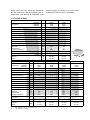
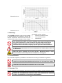
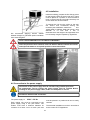
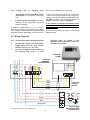
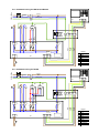
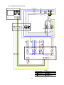
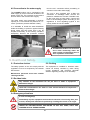
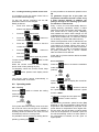
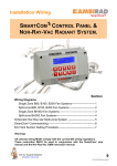
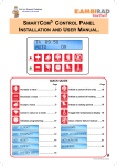
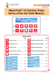
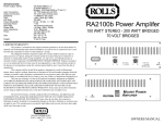
Instruction Manual
ASSEMBLY, INSTALLATION & SERVICING MANUAL
WA & RA EVAPORATIVE COOLERS
INDEX
Section
Introduction and Document Index
Technical Information ----------------------------------------------------- 1
Dimensions ------------------------------------------------------------------ 2
Packaging, Handling and Transportation ---------------------------- 3
Installation -------------------------------------------------------------------- 4
Health and Safety ---------------------------------------------------------- 5
User and Operating Instructions --------------------------------------- 6
Maintenance ----------------------------------------------------------------- 7
Dismantling ------------------------------------------------------------------ 8
WARNINGS
AmbiRad equipment must be installed and maintained in accordance with any relevant
obligations arising from the Health and Safety at Work Act 1974 or relevant codes of
practice. In addition the installation must be carried out in accordance with the current IEE
wiring regulations (BS 7671) and any other relevant British Standards and Codes of
Practice by a qualified installer.
All external wiring MUST comply with the current IEE wiring regulations.
Part No. 703500
Document Index.
GENERAL INFORMATION ............................................................................................................................... 4
User Information ............................................................................................................................................. 4
SECTION 1 – TECHNICAL INFORMATION ..................................................................................................... 4
1.1 Machine identification data ....................................................................................................................... 4
1.2 Introduction ............................................................................................................................................... 4
1.3 Technical information ............................................................................................................................... 5
1.4 Warnings .................................................................................................................................................. 6
1.5 Control Panels .......................................................................................................................................... 6
1.6 Improper use ............................................................................................................................................ 6
SECTION 2 – DIMENSIONS ............................................................................................................................. 7
2.1 RA100 ....................................................................................................................................................... 7
2.2 RA200 ....................................................................................................................................................... 7
2.3 RC100 ...................................................................................................................................................... 8
2.4 RC200 ...................................................................................................................................................... 8
2.5 WA100/150 ............................................................................................................................................... 9
SECTION 3 – PACKAGING, HANDLING AND TRANSPORTATION ............................................................. 9
3.1 Delivery of the unit .................................................................................................................................... 9
3.2 Handling and transportation ..................................................................................................................... 9
3.3 Lifting ...................................................................................................................................................... 10
3.3.1 Lifting with fork lift ........................................................................................................................... 12
3.3.2 Lifting with cables............................................................................................................................ 12
3.4 Unpacking the equipment ....................................................................................................................... 10
3.5 Storage ................................................................................................................................................... 10
SECTION 4 – INSTALLATION ........................................................................................................................ 11
4.1 General Warnings WA evaporative cooling units ................................................................................... 11
4.2 Positioning and Installation of the WA evaporative cooling units ........................................................... 11
4.2.1 Wall installation ............................................................................................................................... 11
4.2.2 Window installation ......................................................................................................................... 11
4.3 General Warnings RA/RC evaporative cooling units ............................................................................. 12
4.4 Positioning and Installation of the RA/RC evaporative cooling units ..................................................... 12
4.4.1 RA roof installation .......................................................................................................................... 12
4.4.2 RC roof installation.......................................................................................................................... 14
4.4.3 RC wall window installation ............................................................................................................ 15
4.4.4 RA wall window installation............................................................................................................. 15
4.5 Installation .............................................................................................................................................. 16
4.6 Connection to the power supply ............................................................................................................. 16
4.7 Wiring diagrams...................................................................................................................................... 17
4.7.1 Control panel with Temperature probe ........................................................................................... 17
4.7.2 Schematic wiring RA150 ................................................................................................................. 18
4.7.3 Schematic wiring RA200 ................................................................................................................. 18
4.7.4 Schematic wiring RC100 ................................................................................................................ 19
4.7.5 Schematic wiring RC200 ................................................................................................................ 20
4.7.6 Multiple coolers ............................................................................................................................... 21
4.7.7 Multiple coolers via Router ............................................................................................................. 22
4.7.8 Multiple coolers via two Routers ..................................................................................................... 23
4.8 Connection to the water supply .............................................................................................................. 24
SECTION 5 – HEALTH AND SAFETY ........................................................................................................... 24
5.1 Protection devices .................................................................................................................................. 24
5.2 Clothing .................................................................................................................................................. 24
5.3 Residual risks ......................................................................................................................................... 24
5.4 Emergency situations ............................................................................................................................. 24
2
SECTION 6 – USER INSTRUCTIONS ............................................................................................................ 25
6.1 General ................................................................................................................................................... 25
6.2 First start-up ........................................................................................................................................... 25
6.3 Remote Command Unit .......................................................................................................................... 26
6.3.1 Command and signal descriptions.................................................................................................. 26
6.3.1.1 Command descriptions ......................................................................................................... 26
6.3.1.2 Signal descriptions ................................................................................................................ 27
6.4 Switching on ........................................................................................................................................... 27
6.5 Switching off ........................................................................................................................................... 27
6.6 Starting mode ......................................................................................................................................... 27
6.6.1 Manual start up ............................................................................................................................... 27
6.6.2 Automatic start up ........................................................................................................................... 27
6.7 Settings ................................................................................................................................................... 27
6.7.1 Setting current time ......................................................................................................................... 27
6.7.2 Setting ON / OFF periods ............................................................................................................... 28
6.7.3 Reading a restored program ........................................................................................................... 28
6.7.4 Modifying a programme .................................................................................................................. 28
6.7.5 Deleting a stored programme ......................................................................................................... 28
6.7.6 Changing the Temperature and Humidity values ........................................................................... 28
6.7.7 Locking/unlocking remote control unit ............................................................................................ 29
6.8 Operating Mode ...................................................................................................................................... 29
6.8.1 Cooling ............................................................................................................................................ 29
6.8.2 Ventilation ....................................................................................................................................... 29
6.9 Operating Faults ..................................................................................................................................... 30
6.10 Bus system ........................................................................................................................................... 30
SECTION 7 – MAINTENANCE ....................................................................................................................... 30
7.1 End-of-Season Maintenance .................................................................................................................. 30
7.2 Pre-Season Maintenance ....................................................................................................................... 30
7.3 Maintenance Safety Regulations............................................................................................................ 31
7.3.1 Clothing ........................................................................................................................................... 31
7.3.2 Unit warnings .................................................................................................................................. 32
7.3.3 Residual risks.................................................................................................................................. 32
7.3.4 Unit warnings .................................................................................................................................. 32
7.4 Technical assistance requests ............................................................................................................... 32
SECTION 8 – DISMANTLING ......................................................................................................................... 32
8.1 Disposal .................................................................................................................................................. 32
3
General Information
User Information
The contents of this document are for
information purposes only and are subject to
modifications without notice;
This manual is to be considered an integral
part of the machine and must be filed in an
accessible place for the workers that use
and maintain the machine.
This manual must be kept in the project file
until final machine dismantling and if the
machine is sold, it must be passed to the
new owner.
The workers using and maintaining the machine
must be fully aware of its contents before the
machine is placed in service.
If the manual is misplaced or damaged,
immediately request a copy by contacting
Technical Assistance Service at AmbiRad
Limited, indicating the identification data of the
plant shown on the machine identification plate
and on the cover of this manual.
If a fault occurs causing machine stoppage,
AmbiRad Limited is not liable in any way for any
damages caused by the stoppage and in no way
is the warranty period extended.
The machine is conforming to the following
European Community Directives:
2006/42/EEC Machinery Directive
2006/95/EEC Low Voltage Directive
2004/108/EEC EMC Directive
UNDER NO CIRCUMSTANCES MAKE MODIFICATIONS TO THE MACHINE AND
ITS INTENDED USE.
AmbiRad Limited declines all responsibility for any damages which may be,
directly or indirectly, caused to exposed persons or property, due to improper
use or use of the machine for different purposes other than the design purposes,
incorrect installation, inappropriate power supply, different or changes to the
installation environment from the one declared during order confirmation, grave
deficiency of maintenance, unauthorized alterations and modifications, use of
non-original spare parts, removal of the protection guards, ignoring the
instructions for use, negligence, etc.
1. Technical Information.
1.1 Machine identification data
1.2 Introduction
area with frequent changes of fresh, filtered and
possibly cool air. For large areas such as
industrial buildings, an air conditioning plant is
not practicable due to the large volume of air to
be cooled and the thermal loads of processes to
be neutralized, requiring very high energy load,
plus the cooling effect is reduced by the exhaust
air extraction plant and frequent opening of
doors during normal activity.
During the summer to improve the internal
environment within a production unit, warehouse
or other area, it is necessary to ventilate the
Evaporative cooling plants that cool the air using
a natural principle represent an optimal solution:
air passes through special wet water filters,
Machine identification data is shown on the
warranty sheet supplied to the customer and is
enclosed in the documentation and on the
machine identification plate.
4
losing part of its heat during the evaporation
process of the water and hence lowering the air
temperature. The absence of refrigeration plant
reduces energy consumption to a minimum and
enables large volumes of air to be treated.
1.3 Technical Data
WA 100
WA 150
kW
10000
7500
5000
15
13000
9700
6500
19
V
230V – 50Hz
230V – 50Hz
Unit
Maximum
Average
Minimum
Air Capacity
3
m /h
Cooling Capacity (1)
Power Voltage
Current
amps
3.7
4.8
Power Consumption
kW
0.9
1.2
Water Consumption (average)*
l/h
34
39
Water Inlet Ø
in
3/8
3/8
Water Outlet Ø
mm
60
60
Air Duct Size
mm
600 x 600
600 x 600
m
5+1 bend
5+1 bend
Maximum Duct Length
Humidification Panel:
Thickness
Surface Area
Saturation Efficiency
Dimensions : L x W X H
mm
m²
%
mm
Weight (empty - full)
Noise Data
Outdoor (2)
Indoor
Air Capacity
Maximum
Average
Minimum
Cooling Capacity (1)
100
100
2
2
88%
88%
1300 x 670 x 1300 1300 x 670 x 1300
kg
dB
A
60 - 75
Min/Max speed
49 / 65
49 / 66
63 - 78
Min/Max speed
50 / 66
50 / 67
H
L
Unit
RC 100
RA 150
RA 200
RC 200
3
10000
7500
5000
13000
9700
6500
20000
15000
10000
25000
18750
12500
m /h
kW
15
19
30
36
V
400V - 50Hz (3pha)
230V - 50Hz
230V - 50Hz
400V - 50Hz (3pha)
amps
3.5
4.8
7.0
7.0
Power Consumption
kW
1.6
1.2
1.8
3.2
Water Consumption (avg)*
l/h
34
43
64
64
Water Inlet Ø
in
3/8
3/8
3/8
3/8
Power Voltage
Current
Water Outlet Ø
mm
60
60
60
60
Air Duct Size
mm
600 x 600
600 x 600
600 x 1150
850 x 470
Static Pressure
pa
80
n/a
n/a
80
Maximum Duct Length
m
See graph page 5
5+1 bend
5+1 bend
See graph page 5
Humidification Panel:
Thickness
Surface Area
Saturation Efficiency
mm
m²
%
100
2.7
88%
100
2.7
88%
100
3.4
88%
100
3.4
88%
Dimensions :
LxWXH
Weight (empty - full)
Noise Data
Outdoor (2)
Indoor
(1)
(2)
mm 1150 x 1150x 1050 1150 x 1150x 1050 1650 x 1150x 1050 1650 x 1150x 1050
kg
dBA
87 - 108
67 - 88
120 - 146
160 - 186
Min/Max speed
55 / 61
56 / 62
Min/Max speed
50 / 66
50 / 67
Min/Max speed
53 / 68
53 / 70
Min/Max speed
58 / 65
60 / 66
test conditions: E. Temp. = 33°C-R. Hum 60%
open field test, 4m distance
5
W
RC100 Fan Curve
RC200 Fan Curve
1.4 Warnings
and possibly cool air, such as:
•
Factories, production areas
•
Commercial premises
•
Warehouses
The ColdAIR evaporative cooler can be installed
in all areas where it is necessary to improve the
internal environment where the area must be
ventilated with frequent changes of fresh, filtered
The equipment must NOT be used for anything other than its designed use for
any reason whatsoever or used in a different way than stated in this manual.
DO NOT install the machine in closed areas; the machine must be installed
outside the area to be treated, except by specific approval of the manufacturer.
Do NOT start-up the machine if it is not connected to the relative plant ( duct ) of
air distribution.
When the plant is operating, do not touch the fan – Mechanical danger. Under
NO circumstance should any work be undertaken on moving parts.
1.5 Control Panels
Any Controllers supplied by AmbiRad are manufactured according to EN 60204/1 regulations.
UNDER NO CIRCUMSTANCE MAKE MODIFICATIONS TO THE CONTROL PANEL.
UNDER NO CIRCUMSTANCE USE WATER TO PUT OUT FIRES
1.6 Improper Use
The unit cannot be used for purposes other than those stated in paragraph 1.4 of this instruction manual.
UNDER NO CIRCUMSTANCE INSTALL COLD AIR EVAPORATIVE COOLING
PLANTS IN POTENTIALLY EXPLOSIVE ENVIRONMENTS.
6
2. Dimensions.
2.1 RA150
Section C - C
A: Water Inlet
B: Water Outlet (drain)
C: Wiring Connections
2.2 RA200
Section A - A
7
A: Water Inlet
B: Water Outlet (drain)
C: Wiring Connections
2.3 RC100
Section A - A
A: Water Inlet
B: Water Outlet (drain)
C: Wiring Connections
2.4 RC200
Section A - A
8
A: Water Inlet
B: Water Outlet (drain)
C: Wiring Connections
2.5 WA100/150
A: Water Inlet
B: Water Outlet (drain)
C: Wiring Connections
3. Packaging, Handling and Transportation.
3.1 Delivery of the unit
When the unit is delivered, the customer MUST
check the condition of the goods
Check the packaging and its contents, if damage
due to transportation is found, record the
damage on the shipping documents to be signed
by the shipping agent and send a copy by fax to
AmbiRad Limited
3.2 Handling and transportation
Take care when handling Evaporative Cooling units. During off loading, handle
and position to avoid damage to the equipment. Avoid contact with elements,
which may damage the equipment.
AmbiRad Limited declines any responsibility for damage caused during
transportation, loading and off loading of the evaporative cooling units.
9
3.3 Lifting
3.3.1 Lifting with fork lift
damaging the bottom of the machine.
Widen the forks as much as possible to balance
the load. Dip the ends of the forks to avoid
3.3.2 Lifting with cables
We suggest to attach the cables as shown,
inserting spacers of an adequate length to
prevent the cables from damaging the casing
when tightened.
Because of the heavy weight, RC models, when
unpacked, are provided with punched brackets
to allow to lift them by using appropriate metal
tubes.
Place goods down with care. Avoiding dropping and sudden movements.
UNDER NO CIRCUMSTANCE remain under suspended loads and inside the
movement area of the lifting equipment.
Make sure that the capacity of the lifting equipment is adequate for the weight of
the machine.
Lifting must only be carried out by qualified personnel.
3.4 Unpacking the equipment
Leave the equipment on its transportation
packaging base with any protection guards
mounted, so that the lower part is raised
from the floor to avoid damage, until the unit
is installed.
Free all the components from the packaging
material and collect the packaging to avoid
potential danger of fire and suffocation of
persons or animals.
Disposal of packaging materials must conform to the regulations in force in the
country of destination where the evaporative cooling unit is installed
3.5 Storage
During transportation and storage, make sure
that the environmental temperature is between
10 and 50 °C.
If the ColdAIR evaporative cooling unit must be
stored, make sure that the relative humidity in
the warehouse is between 5% and 90%.
10
4. Installation WA Units.
4.1 General Warnings about installing
WA units.
wall until it makes contact with the rear
mountings of the bracket
Before proceeding to install, make sure that
each evaporative cooling unit has been
unpacked and checked for damage.
Fix the cooling unit using the appropriate side
brackets and the self tapping screws provided.
Positioning and installation of the evaporative
cooling units must be carried out by qualified
personnel and by observing the laws in force in
the country of destination.
4.2.2 Window installation
Fix the window bridge to the window after the
hole for the air duct has been made. Refer to
dimensional sketch below.
4.2 Positioning and Installation of
WA Series evaporative cooling units.
Fix the supplied support bracket at the prepared
frame.
4.2.1 Wall installation
On the rear side of the cooling unit (fan side),
prepare the first section of air duct (box section
600 x 600mm)
Fix the support bracket to the wall after the hole
for the air duct has been made. Refer to
dimensional sketch below.
On the rear side of the cooling unit (fan side),
prepare the first section of air duct (box section
600 x 600mm)
Position the cooling unit onto the support
bracket, pushing the cooling unit towards the wall
until it makes contact with the rear mountings of
the bracket
Position the cooling unit onto the support
bracket, pushing the cooling unit towards the
Fix the cooling unit using the appropriate side
brackets and the self tapping screws provided.
11
WALL INSTALLATION
WINDOW INSTALLATION
WINDOW INSTALLATION. SUPPORT
BRACKET NOT SUPPLIED WITH THE UNIT
TO BE MADE BY THE CUSTOMER
WALL INSTALLATION. SUPPORT BRACKET
SUPPLIED WITH UNIT
Installation RA/RC Units.
4.3 General Warnings about installing
RA/RC units
Before proceeding to install, make sure that
each evaporative cooling unit has been
unpacked and checked for damage.
Positioning and installation of the evaporative
cooling units must be carried out by qualified
personnel and by observing the laws in force in
the country of destination.
4.4 Positioning and Installation of RA/
RC series evaporative cooling units.
It is recommended to apply silicone sealant
between the two flanges to guarantee a perfect
water tight seal.
4.4.1 Roof mounted RA Evaporative
coolers.
Prepare and secure the air inlet duct onto the
roof structure. (The unit is equipped with a
mating duct flange for direct attachment).
DUCT DIMENSIONS:
RA 150
= 600 X 600mm
RA 200
= 600 X 1150mm
Position the base of the cooling unit onto the
duct flange using fixings provided.
12
Ensure all strips are seated correctly in their
grooves.
Check that the clamp holding the flexible hose to
the pump is tight.
Position and secure the four posts to each
corner of the cooling unit base using the screws
provided.
Insert the water distributor into the grooves of
the humidification panels ensuring the supports
of the water distributor are in a uniform manner
on the strips.
Noting the position of the water pump in the unit,
make a hole through the panel for the hose end
fitting.
Position and secure the humidification panels by
sliding them between the guides of each side
post.
Ensure the groove, on one side of the panel, is
uppermost.
Secure the fitting with a hose clamp and
complete the water connections to the pump.
Insert the grilles onto the sides of the panels
using clips provided
Insert the water distribution strips into the
grooves on each panel.
13
Once all four protection grilles have been
secured, locate and fix the top of the unit using
the screws provided.
Note: DO NOT ASSEMBLE THE GRILLE AT
THE
FRONT
OF
THE
MACHINE
(CONNECTIONS / COMPONENTS SIDE). The
grille can be inserted later without clips to aid
maintenance.
Insert the clips downwards to their first positive
stop.
Once all the clips are in position, push fully
home until they are level with the top of the
panels.
4.4.2 Roof mounted RC Evaporative
coolers
Prepare and fix an air inlet flanged duct and a
frame to hold up the unit. The flange has to be
of the same dimension of the unit’s trunk duct
flange.
The unit is equipped with a section of flanged
duct that will be fixed to the flange of the inlet
duct already prepared and with two side bars
that will be fixed to the prepared frame.
Verify that the frame is designed to support the
weight of the machine, doesn’t cause vibrations
and is perfectly horizontal. It may be necessary
to insert anti-vibration dampers between frame
and the bars, this needs to be planned before
manufacturing the frame and consider fitting
flexible couplings in the water connections.
14
Position the evaporative cooler on the inlet duct.
Position the evaporative cooler on the inlet duct.
Fix the two flanges (base duct flange-inlet duct
flange) together and the bars at the frame by
using provided bolts.
Fix the two flanges (base duct flange-inlet duct
flange) together and the bars at the frame by
using provided bolts.
We recommend fitting an outlet flexible
connection between the two flanges to avoid
vibrations transmitted through the ducts.
We would suggest to insert an outlet flexible
connection between the two flanges to avoid
vibrations transmitted through the ducts.
We recommend applying silicone sealant
between flanges to guarantee perfect insulation
from external agents.
4.4.4 Wall/Window
evaporative coolers
4.4.3 Wall/Window
evaporative coolers
Prepare and fix an air inlet flanged duct and a
frame to hold up the unit.
mounted
RC
mounted
RA
Prepare and fix an air inlet flanged duct and a
frame to hold up the unit.
The flange has to be of the same dimension of
the unit’s trunk duct flange.
The flange has to be of the same dimension of
the unit’s trunk duct flange.
The unit is equipped with a trunk of flanged duct
that will be fixed to the flange of the inlet duct
already prepared and with two side bars that will
be fixed on the frame.
The unit is equipped with a trunk of flanged duct
that will be fixed to the flange of the inlet duct
already prepared and with two side bars that will
be fixed on the frame.
Verify that the frame is designed to support the
weight of the machine, doesn’t cause vibrations
and is perfectly horizontal.
Verify that the frame is designed to support the
weight of the machine, doesn’t cause vibrations
and is perfectly horizontal. It may be necessary
to insert anti-vibration dampers between frame
and bars, this needs to be planned before
manufacturing the frame and consider fitting
flexible couplings in the water connections.
Position the evaporative cooler to the inlet duct.
Fix the two flanges (base duct flange-inlet duct
flange) together by using bolts provided.
15
4.5 Installation
Inside the building, prepare the first fixings points
for the support chains of the air inlet duct. These
must be placed in a position to avoid excessive
force on the air inlet duct and make sure they are
on the same axis as the machine.
To support the unit from the ceiling or the wall,
use chains and accessories having the
necessary test certificates, made from
zinc
-plated steel or stainless steel and having a wire
diameter of no less than 3 mm or
dimensioned for the weight to be supported, bear
in mind safety margins imposed by regulations.
We recommend applying silicone sealant
between flanges to guarantee perfect insulation
from external agents.
DO NOT USE ALUMINIUM ALLOY OR SIMILAR COMPONENTS
Once the plant has been installed, rotate the diffuser blades towards the exterior
and adjust the blades to an optimal position to direct the airflow.
4.6 Connection to the power supply
Connection to the power supply must be carried out by qualified personnel.
All components used to connect the power supply must be certified. Before
working on the power supply cables, make sure that power is cut-off.
Provide an efficient earth connection .
The power supply is:
230 V ~ 50 Hz
must be placed in a position that can be easily
reached.
Each cooling unit must be connected to the
power supply using a two pole switch. The
isolator must have a distance between its
contacts of at least 3 mm for each pole and
The electrical installation must be in accordance
to the current I.E.E. Regulations.
16
The
cooling
unit
is
supplied
•
An Electrical board and Main power
inlet switch for connection, near to the
unit.
•
A Control panel with display for remote
command of the equipment, positioned
inside the building.
be covered. (*WA/RA units **RC units)
with:
A multi-core cable with 5 cores, for connection
of the remote control panel to the cooling unit.
Make the connection using shielded cable type
20 AWG - 5 core with a minimum section of
0.5mm² - Maximum length of 25 meters.
It is essential to maintain the polarity of the
electrical phases and the numbers on the
wires/terminals.
A multi-core cable made of 2* or 4** core +
earth, for connection to the power supply: Make
the necessary cable extensions using cables of
adequate sections depending on the distance to
Connections are made as shown on the wiring
diagram below.
4.7 Wiring Diagrams
4.7.1 Control Panel with Temperature Probe
•
screened cable as shown in the
diagram below, connect the ’screen’ of
the cable to the earth.
Connect the cooling unit to the power
supply using the 2*/4** pole isolator
switch. (*WA/RA units **RC units)
Connect the Remote Control Panel to
the Cooling Unit using a 5 core
•
CONTROL
PANEL
brown
white
green
yellow
grey
yel/grn
brown
brown
brown
blue
COOLER
TERMINAL
CONNECTIONS
m
/s
grey
yellow
Screened
cable 5 x
0.5mm²
green
white
brown
brown
brown
L3
L2
brown
1
blue
yellow/green
Note: grey cable used for optional BMS control.
17
Power supply
WA/RA 230V~50Hz
RC 400V~50Hz
230V~50Hz
4.7.2 Schematic wiring for WA100 and RA150
FUSE
brown
blue
yellow/green
L
N
A3
V- L2 L1 V+
M1
M
M
Y1
S1
M4
I
II III
m V- L2 L1 V+
s
/
red
blue
black
white
A1
6 5 4 3
2 1
FUSE
1314
grey
yellow
green
white
brown
10 9 8 7
blue
brown
1211
A1
A2
A3
M1
M4
S1
S2
Y1
V+ L1 L2 V- ms
/
A2
S2
Legend
Main Switch
PCB
Control Panel
Fan
Pump
Drain
Float switch
Inlet Valve
230V~50Hz
4.7.3 Schematic wiring for RA200
FUSE
brown
blue
yellow/green
L
N
A3
M1
M4
M2
M
M
Y1
V- L2 L1 V+
M
S1
I
II III
I
II III
m V- L2 L1 V+
s
/
red
blue
black
white
A1
6 5 4 3
2 1
FUSE
1314
A2
S2
V+ L1 L2 V- ms
/
18
grey
yellow
green
white
brown
10 9 8 7
blue
brown
1211
A1
A2
A3
M1
M2
M4
S1
S2
Y1
Legend
Main Switch
PCB
Control Panel
Fan 1
Fan 2
Pump
Drain
Float switch
Inlet Valve
yellow/green
blue
brown
grey
black
N
L3
L2
L1
FUSE
FUSE
FUSE
M1
V- L2 L1 V+
A3
415V/3P~50Hz
4.7.4 Schematic wiring for RC100
M
6 5 4
L1 L2 L3
3 2 1
L1 L2 L3
m V- L2 L1 V+
s
/
KM1
A1
KM2
T1 T2 T3
T1 T2 T3
M
Y1
S1 KM1 KM2
M4
I
10 9 8 7
2 1
6 5 4 3
grey
yellow
green
white
brown
blue
brown
1211
II III
FUSE
1314
V+ L1 L2 V- ms
/
A2
S2
A1
A2
A3
KM1
KM2
19
Legend
Main Switch
M1
PCB
M4
Control Panel
S1
1st Speed contactor S2
2nd Speed contactor Y1
Fan 1
Pump
Drain
Float switch
Inlet Valve
yellow/green
blue
brown
grey
black
FUSE
FUSE
FUSE
M2
V- L2 L1 V+
A3
N
L3
L2
L1
415V/3P~50Hz
4.7.5 Schematic wiring for RC200
M1
M
6 5 4
L1 L2 L3
M
3 2 1
L1 L2 L3
6 5 4
L1 L2 L3
3 2 1
L1 L2 L3
m V- L2 L1 V+
s
/
KM1
A1
KM2
T1 T2 T3
T1 T2 T3
M
Y1
S1 KM1 KM2
M4
I
10 9 8 7
2 1
6 5 4 3
grey
yellow
green
white
brown
blue
brown
1211
II III
FUSE
1314
V+ L1 L2 V- ms
/
A2
S2
A1
A2
A3
KM1
KM2
20
Legend
Main Switch
M1
PCB
M2
Control Panel
M4
1st Speed contactor S1
2nd Speed contactor S2
Y1
Fan 1
Fan 2
Pump
Drain
Float switch
Inlet Valve
The system comprises of:
•
1 Control panel display unit.
•
1 ColdAIR evaporative cooler acting as a
master.
•
Up to a max of 3 routers each having a
max of 4 ColdAIR evaporative coolers as
slaves.
4.7.6 Multiple Coolers
Multiple ColdAIR evaporative coolers can be
connected into one system via a single control
panel and one or more router modules.
When designing the system, the siting of the
evaporative coolers and control panel must be
carefully considered, as the sensor is built into
the controller. Max distance between router and
the coolers is 200m.
System examples shown below.
1 Router
(max 5 coolers)
2 Routers
(max 9 coolers)
3 Routers
(max 13 coolers)
21
230V ~ 50Hz
L
N
22
MASTER COOLER
TERMINAL CONNECTIONS
m V- L2 L1 V+
/s
L1 L2 L1 L2
max.200m
V- L2 L1 V+
DISPLAY MODULE
L1 L2 L1 L2
ROUTER
L1 L2 L1 L2
max.200m
1 2
V- V+
SLAVE COOLER
TERMINAL CONNECTIONS
m V- L2 L1 V+
/s
m V- L2 L1 V+
/s
SLAVE COOLER
TERMINAL CONNECTIONS
max.200m
SLAVE COOLER
TERMINAL CONNECTIONS
m V- L2 L1 V+
/s
m V- L2 L1 V+
/s
SLAVE COOLER
TERMINAL CONNECTIONS
All coolers and routers must be connected to 230V mains supply.
*Interconnecting between Display Module and Router must be used using screened cable.
SLAVE COOLER(S):
Connect terminals L1 and L2 to the router outlet terminals L1 and L2.
Add a jumper cable between terminals M/S and V-.
Maximum cable run between router and cooler(s) is 200m.
MASTER COOLER:
Connect terminals L1 and L2 to the router input terminals L1 and L2.
Do not use V+ and V-.
Maximum cable run between router and cooler is 200m.
DISPLAY MODULE:
Connect terminals L1, L2, V+ and V- to router input terminals L1, L2, V+ and V- using 4 x 0.5mm²
screened cable.
Maximum cable run between display module and router is 200m.
NOTES
4.7.7 Multiple coolers via Single Router
Diagram for use with Display Module model ref SCP015V110 only.
Please consult supplier for display module ref SCRE10A/SCRE50D
230V ~ 50Hz
L
N
23
L1 L2 L1 L2
MASTER COOLER
TERMINAL CONNECTIONS
/
m V- L2 L1 V+
s
L1 L2 L1 L2
ROUTER
L1 L2 L1 L2
1 2
V- V+
L1 L2 L1 L2
max.200m
V- L2 L1 V+
DISPLAY MODULE
L1 L2 L1 L2
ROUTER
L1 L2 L1 L2
max.200m
1 2
V- V+
SLAVE COOLER
TERMINAL CONNECTIONS
/
m V- L2 L1 V+
s
SLAVE COOLER
TERMINAL CONNECTIONS
/
m V- L2 L1 V+
s
/
m V- L2 L1 V+
s
/
m V- L2 L1 V+
s
SLAVE COOLER
TERMINAL CONNECTIONS
max.200m
SLAVE COOLER
TERMINAL CONNECTIONS
max.200m
SLAVE COOLER
TERMINAL CONNECTIONS
/
m V- L2 L1 V+
s
SLAVE COOLER
TERMINAL CONNECTIONS
/
m V- L2 L1 V+
s
/
m V- L2 L1 V+
s
SLAVE COOLER
TERMINAL CONNECTIONS
/
m V- L2 L1 V+
s
SLAVE COOLER
TERMINAL CONNECTIONS
All coolers and routers must be connected to 230V mains supply.
*Interconnecting between Display Module and Router must be used using screened cable.
SLAVE COOLER(S):
Connect terminals L1 and L2 to the router outlet terminals L1 and L2.
Add a jumper cable between terminals M/S and V-.
Maximum cable run between router and cooler(s) is 200m.
MASTER COOLER:
Connect terminals L1 and L2 to the router input terminals L1 and L2.
Do not use V+ and V-.
Maximum cable run between router and cooler is 200m.
DISPLAY MODULE:
Connect terminals L1, L2, V+ and V- to router input terminals L1, L2, V+ and V- using 4 x 0.5mm²
screened cable.
Maximum cable run between display module and router is 200m.
NOTES
4.7.8 Multiple coolers via two Routers
Diagram for use with Display Module model ref SCP015V110 only.
Please consult supplier for display module ref SCRE10A/SCRE50D
from the 3/8” connection before proceeding to
connect it to the main water supply.
4.8 Connection to the water supply
The ColdAIR cooling unit is connected to the
water supply by a 3/8” connection located on the
bottom of the unit. The customer must provide a
shut off valve to the machine inlet supply.
The unit is also equipped with a Ø63 mm
connection to discharge water, remove the
protection material and connect a flexible hose,
fix the hose using a hose clamp. Connect the
hose to the discharge system according to the
regulations in force regarding hygiene in the
country where the unit is installed.
The water supply must guarantee a minimum
capacity of 5 -10 Lt/minute at a pressure of 1.5 3 bars. (maximum pressure allowed: 6 bars ).
It is advisable to install the water distribution
inside the building, to protect it against freezing
during winter and also make sure it can be
emptied if necessary; on the contrary, insulate it
adequately. Remove the protection material
ATTENTION: DO NOT use excessive
force when connecting either the
water supply and discharge hose to
their respective connections.
5. Health and Safety.
5.1 Protection devices
5.2 Clothing
The safety systems on the unit comply with the
regulations in force as required by the relevant
EU Directive.
The equipment is installed in locations which
cannot be directly reached by users during
normal operations and therefore particular
attention regarding clothing is not necessary.
Maintenance personnel must wear suitable
clothing and PPE
5.3 Residual risks
Pay attention to fan movement. Do not put arms or limbs in equipment. –
Mechanical danger
Under NO circumstances use water to clean electro-mechanical components –
Electrocution danger
5.4 Emergency situations
In case of emergency:
Immediately stop the equipment and isolate the electrical circuit using the 2 pole
isolator, identify and eliminate the problem by checking the causes of its origin.
UNDER NO CIRCUMSTANCES USE WATER TO PUT OUT FIRES, ONLY USE
POWDER OR CO2 EXTINGUISHERS
24
6. User and Operating Instructions.
6.1 General
6.2 First Start-up
The operation of the evaporative cooler is based
on an important principle. It introduces large
quantities of fresh air into the building and
removes hot unpleasant air through the doors,
windows and other openings. If the system is
not able to expel the volume of air being
introduced, the efficiency of the system will be
compromised.
6.2.1 All models
ATTENTION:For
correct
and
optimal
operation and use of the plant/machine it is
essential that during the first “start-up”
operation (in cooling mode), the fan is
operated at minimum speed and maintained
at this speed for at least one complete day.
If this procedure is not observed, during the
first day of use only, malfunctioning of the
evaporative panels may occur resulting in
water drops coming out of the ducts.
INLET FRESH AIR = OUTLET HOT AIR. A very
simple principle.
If the system is able to expel all the air
introduced, the system will operate at its
maximum efficiency level.
During the first start-up of the cooling system, an
unusual odour may be detected which may be
present for several hours. This odour is a
characteristic of the treated cellulose material
but it is not harmful.
The ideal condition is to position the air diffusers
away from the openings (windows, doors, etc.)
in the building. By opening a window far away
from the diffusers, the air will pass through the
building and cool it down. Maximum efficiency
can be reached by adjusting the dimensions of
the window and door openings Never close the
openings: if they are closed, no changes of air
will occur, consequently reducing the cooling
effect and increasing the relative humidity level
inside the building.
6.2.2 RC models only
During first start-up, ensure correct rotation of
the fan (as indicated on fan body):
1. Remove cover by unscrewing the 4 corners
screws.
2. Enable ventilation mode
3. Check direction of motor.
4. If the fan rotates in the wrong direction,
exchange the L1 and L2 connections at the
main power supply switch.
5. Re-check direction of motor.
6. Replace cover.
To optimize efficiency, take into account the
following openings for air expulsion: Guarantee
about 1m² area of extraction for every 1000m³ of
treated air (refer to the project data).
Check the tightness of the belt.
A good rule for all evaporative coolers is that the
more “dry” the external air is, the greater the
temperature difference or the cooling capacity
that can be reached. An air cooler will not
operate at maximum efficiency on very humid
days but it will still reach an efficient cooling
level.
To avoid any undue noises and ensuring long
life, the drive belt will require adjusting after the
first few hours of operation.
To check the belt, proceed as follows:
Place a perfectly straight bar on the two pulleys.
Apply a light force on the middle of the belt and
measure the distance of the flex of the belt. The
distance should be between 10 and 15mm. Re
-adjust where necessary. Do not over tighten as
this will reduce the life of the belt and may cause
the fan shaft to deform and overload the
bearings.
In areas with high relative humidity, the air
cooler must be oversized to guarantee more air
changes, or in other words, it must have a
higher capacity to compensate the smaller
temperature difference. In these areas, the
maximum cooling effect will be reached by
making sure that there are more air evacuation
points than those normally used and that the
units are already operating early in the morning
to avoid the build-up of latent heat inside the
space to be cooled. The design of the system
will take into account local climatic conditions.
Check the operating current of the motor against
the rating plate. If the value is higher, this is
normally the result of overestimating the
pressure drop in the system, and must be
corrected by adjusting any dampers and/or the
transmission ratio by changing one of the two
pulleys.
On days when the relative humidity level is near
to or more than 70%-75%, it is advisable to
operate the system in ventilation only mode.
25
6.3 Remote Command Unit
ColdAIR cooling units are equipped with a
remote control panel, which enables the user to
control: SWITCHING - ON / OFF , COOLING /
VENTILATION , VENTILATION FAN SPEED
ADJUSTMENT,
TEMPERATURE
AND
RELATIVE
HUMIDITY
DISPLAY
/
ADJUSTMENT.
The panel contains logic which enables several
functions necessary for good operation of the
cooling unit. Periodic panel washing and end-of
cycle rinsing. These functions are essential to
maintain optimum working conditions of the
cooling unit.
6.3.1 Command and signal descriptions
enables the user to set the day, hour
and minute values.
6.3.1.1 Command descriptions
If time is displayed, sets the current
hour.
Pressed once during On/Off periods
setting, changes hours.
Pressed once during modifying default
parameters, increases the value.
Pressed once after pressing FAN
command, increases fan speed and/or
disables automatic fan speed.
Pressed for more than 2 seconds
together with M command, changes
the default parameters.
Pressed for more than 1 second,
switches the cooling unit on or off.
Pressed once during setting On/off
periods, exits the menu.
Pressed once during modifying default
parameters, exits the menu.
Pressed for more than 3 seconds,
when the control unit is locked,
temporary unlocks.
In the OFF position, the Display
shows:” 0FF ”.
(the panel is always powered-on)
If time is displayed, sets the current
minutes.
Pressed once during On/Off periods
setting, changes minutes.
Pressed once during modifying default
parameters, decreases the value.
Pressed once after pressing FAN
command, decreases fan speed and/
or disables automatic fan speed.
Pressed for more than 2 seconds
together with H command, changes
default parameters.
Pressed once, selects fan speed (F1,
F2, F3…). or automatic operation (FA)
Pressed once, selects programming
mode to display or set operating
periods / automatic shutdown.
Pressed for more than 1 second
selects operating mode: Cooling ON
(manual), Cooling AUTO (automatic),
Ventilation ON (manual), Ventilation
AUTO (automatic).
Pressed during programming, selects
automatic operating conditions ( ON /
OFF ) for the period
Pressed once, shows the temperature
detected.
Pressed once, shows the humidity
detected.
If time is displaying, sets the current
day.
Pressed once during programming
operations, selects the days of the
programme being set.
Pressed till display
displays current time.
Pressing the
shows
In both cases, pressed for more than 5
seconds until “SET“ is displayed,
allows the user to set the relative
humidity.
‘time’
Use the
buttons to increase
or decrease the value.
buttons
26
6.3.1.2
Signal Descriptions
6.4 Switching ON
The led indicates if the timer
(Automatic programme) is in On or Off
Press the
button for more than 2 seconds,
until the time is displayed.
The led indicates that the unit is
working in manual cooling mode.
6.5 Switching OFF
The led indicates that the unit is
working in automatic cooling mode
(depending on the programme set)
The led indicates that the unit is
working in manual ventilation mode.
The led indicates that the unit is
working in automatic vent mode
(depending on the programme set)
When the led is on, the day of the
week is shown: 1= Monday …..
Blinks during modifying values or
parameters.
oFF
FAn
P-00
Unit off. Attention: the panel is
always powered-on.
button for more than 2 seconds,
until the display shows “oFF”.
6.6 Starting mode
6.6.1 Manual start mode
With the unit switched on, press the
.
button several times until the led goes on the
corresponding operation mode required:
6.6.2 Automatic start mode
With the unit switched on, press the
.
button several times until the led goes on the
corresponding operation mode required:
Ventilation mode only.
STARTING COOLING - Waits for the
drain valve to close and turns the
water pump on.
Cooling
6.7
P-01
COOLING.
P-02
DRAIN
Cln
SELF CLEANING
StOP
Press the
Ventilation
Settings
6.7.1 Setting current time
Press the
button for more than 2 seconds
until display shows “timE”.
End of program - oFF period
Release the key, display shows the current time
Loc
Control unit locked
for approx 5 seconds or until the
- -:- -
Free space in memory
--
Temperature and
disconnected
humidity
pressed.
probe
En
Communication doesn’t work properly.
Check wiring connections.
EE
Eeprom failure. Try to power off and
on again.
EA
TIME OUT filling or draining tank
failure. Try to power off and on again.
If error reoccurs, maintenance maybe
required.
Etc
button is
Clock error. The time on the remote
controller is not set. Set current time. 27
At any time the time menu is activated, the
symbol is displayed.
Use the
.
button to set the day of the week.
ie 1 = Monday, 2 = Tuesday , 7 = Sunday.
Use the
button to set the current hour.
Use the
button to set the current minute.
Press the
seconds.
button to return or wait five
6.7.2 Setting On/Off periods
Press the
To save changes press the
button several times until
To exit the program settings, press the
Button or wait 30 seconds.
display shows “PR9”.
Release the key, display shows the first
program position “--:--” and the
button.
6.7.5 Deleting a stored program.
symbol is
Press the
displayed.
and the display shows the first
programmed position along with the
Use the
.
symbol
button to set the day or multiple
Press the
days required.
button to select the program to
be deleted.
Use the
and
buttons to set the
To delete a selected program, press and hold
ON and oFF times required.
Press the
the
button to set the mode:
button until the display changes to
“--:--”
To delete all stored programmes, press and hold
Led
on = Cooling
Led
the
“EALL”
on = Ventilation
Led
To exit the program settings, press the
Button or wait 30 seconds.
on = unit ON
Led
off = unit oFF
6.7.6 Changing
Humidity values
To save the program and advance to the next
program, press the
button. If you want to
exit without saving, press the
. button until the display changes to
the
Temperature
.
and
Factory setting: Temperature : 26 °C
Relative humidity: 75%
button or
wait 30 seconds.
To exit the program settings, press the
Button or wait 30 seconds.
Press and hold the
.
displayed (then release the key). The display
shows the set point along with the
6.7.3 Reading a stored program.
Press the
and the display shows the first
programmed position along with the
Further presses of the
button until “SP“ is
Use the
symbol
buttons to increase or
decrease the value.
button will display
To save changes press the
10 seconds.
other programmes stored.
To exit the program settings, press the
Button or wait 30 seconds.
&
.
Press and hold the
button or wait
button until “SP“ is
displayed (then release the key). The display
6.7.4 Modifying a program.
shows the set point along with the
Press the
Use the
and the display shows the first
programmed position along with the
Press the
symbol.
&
symbol.
buttons to increase or
decrease the value.
symbol
To save changes press the
10 seconds.
button to select the program to
be altered. Refer to section 6.7.2 settings.
28
button or wait
6.7.7 Locking/unlocking remote control unit.
It’s also possible to set automatic speed function
FA
It is possible to lock the remote control unit to
avoid unauthorised tampering
To guarantee longer life of the pads, the
evaporative refreshes the tank’s water every
4 hours (factory default). In addition, the
pads go through a self cleaning cycle when
the machine is switched off.
To lock the remote command unit the HL
parameter value must be changed.
Modify as follows:
•
Press and hold the
&
.
Every 4 hours, the unit automatically alters to
cooling stand-by (ventilation mode). It drains
water from its tank and re-fills it with fresh water,
then reverts back to cooling mode. (Elapsing
time between the tank’s water change can be
modified depending on environmental conditions
and/or kind of water inlet. To make this change
it’s necessary to call the after-sales service).
buttons until display shows PA.
•
Press the
•
Press the
button twice.
or
buttons to
locate the HL parameter.
•
alter the set value.
When the evaporative cooler is switched off, the
unit automatically starts a pads self clearing
cycle lasting 10 minutes. During which time, it
drains water from its tank and re-fills it with fresh
water, performs a water re-circulation through
the pads (ventilation off) to remove residual
salts and other kind of dirtiness.
Press the
At the end of cycle the machine drains the water
from the tank.
Press the
button to view the
current set value.
•
•
Press the
or
buttons to
button again to go back.
To save changes press the
30 seconds.
button or wait
6.8.2 Ventilation
When the remote control is locked, display
shows “Loc” when pressing any key.
Press the
button to choose the ventilation
mode required:
To temporary unlock the remote control, keep
(manual)
the
button pressed until display shows
“oFF”
(automatic)
The remote control returns automatically to
locked status after 15 seconds.
6.8
Press the
speed.
Operating mode
button to display the current fan
Press the
6.8.1 Cooling
or
buttons to set the
fan speed desired or the automatic speed
Press the
button to choose the cooling
function “AUtO”
mode required:
To save the changes and exit press the
(manual)
or
(automatic)
buttons or wait 1 second.
Air flow during automatic speed function (FA)
depends on the set temperature value and the
temperature value detected by the probe. If the
probe detects a temperature value higher than
the set value, the fan will start on higher speed
until the set temperature is reached. Upon the
fan will automatically revert to a lower speed. If
the temperature increases, the fan goes on
higher speed.
If the probe detects a humidity value more than
5% of the set value, the unit goes in ventilation
mode (cooling stand-by) If the probe detects a
humidity value less than the set value, the unit
automatically reverts to cooling mode.
It’s possible to set the air flow by altering the fan
speed by pressing the
.
button
29
•
•
•
6.9 Operating faults
If during normal operation of the unit, the “EA”
code appears on the control panel, it could be
that either foreign bodies (e.g.: leaves, etc.)
have accumulated around the discharge valve
blocking the evacuation of the water, or that the
level switch is faulty.
Cut-off electrical power;
Close the water tap;
Get in touch with the installer or a
qualified technician.
6.10 Bus system
Certain models have an on-board printed circuit
that allows to have a BUS System connection
called CBS or a single command control system
called CABS. The CBS system can be
controlled by a P.C. and can control up to 58
units. The CABS System can control groups of 5
unit controlled by a single remote command. It is
possible to have these systems implemented
even after the cooling system is installed.
In order to reset the error, remove power from
the unit. If the error code reappears on returning
power to the unit, contact the installer or the
after sales service.
If water drips continuously through overflow
holes during normal operation, it is probably due
to a faulty level switch. Contact the installer or
after sales service.
For further information, please contact AmbiRad
Ltd.
In both cases it would be best to:
•
Shutdown the plant:
7. Maintenance.
7.1 End-of-Season Maintenance
At the end of each season, it is recommended
that the following precautions be taken to make
sure the system operates efficiently at the start
of the following season.
•
• Cut-off power to the unit using the main
•
•
•
•
•
isolator-switch.
Close off the water supply.
Drain the water supply pipe work to avoid
bursts due to icing.
Remove the machine cover.
Check that the water channels are clean
•
and that there are no obstructions in the
water supply and distributor in the upper
part of the unit. Clean any debris in the
water riser.
Delicately and fully clean the base of the
unit. Use a mild detergent, not a solvent
as it may react with plastic materials.
Remount the cover and make sure it is
fixed securely using the bolts supplied.
Apply the protection cover over the unit
making sure that it has no holes or
damage, if damage is detected, repair
the cover or replace.
It is very important that the protection cover is applied to the evaporative cooler
at the end of the season, this avoids the machine from being damaged by
climatic factors during the set-aside period; smog, acid rain , ice, etc.
7.2 Pre-Season Maintenance
•
•
We recommend annual service to the system to
maintain it in perfect operating conditions.
•
•
•
•
Cut-off power to the unit using the main
isolator switch.
Remove the protection cover and check for
any damage that may have occurred. Clean
the cover with mild detergent and put into
storage.
Remove the unit cover
•
30
If necessary clean the base.
TC models: check the tightness of the belt
(*) – (see sect 6.2.2). When damaged it
must be changed.
Check the evaporative pads and clean them
thoroughly using water. Replace where
necessary.
Check that waterways are clean and that
there are no obstructions in the water
supply and distributor in the upper part of
the unit. Clean any debris in the water
pump.
•
•
•
•
Turn the machine on by the main isolator
switch.
Turn on the water supply. Start the system
in COOLING mode and check that the
discharge valve is closed and that the tank
fills up with water until the inlet valve stops.
Check that the water is distributed evenly
on all evaporative pads.
Check that the discharge valve is working
•
•
•
properly; make sure that it opens within 5
minutes after having pressed the OFF key.
Check for any water leaks.
Check cables conditions.
Replace and fix well the machine top using
the bolts supplied.
(*) During working season, it is advisable to check it
monthly.
Before carrying out any maintenance operations, carefully read this section of
the manual. For any necessity, contact Technical Assistance Service.
The manufactures are not responsible for any damage or malfunctions due to
lack of maintenance as described in this section.
7.3 Maintenance Safety Regulations
Before machine start-up the equipment should
be checked to make sure it is working correctly,
so that any maintenance or repairs necessary
can be carried out before the operating period.
7.3.1 Clothing
Maintenance personnel must wear suitable
clothing and PPE.
The manufacturer does not assume any responsibility or is liable for any
guarantee; due to damage caused by not abiding to instructions, any non
compliant installations and inappropriate use of the equipment by the end user.
date, time, type of service undertaken and the
name of the person.
During maintenance operations, barrier off the
working area in compliance with H & S
regulations.
If any cleaning solvents are used, make sure to
avoid damage to electrical cables.
Record and log all maintenance carried out on
an appropriate register, making sure to state the
Personnel that use any solvents must be equipped with individual protection
(safety glasses, filter masks, gloves) suitable for contact with the solvent used.
When using solvents under no circumstance smoke or use open flames. After
use, ventilate the building to extract any residual vapours.
Under no circumstance:
Leave any flammable materials near to electrical panels.
Work on the electrical equipment without isolating the equipment from
the power supply lines.
Work on any part of the unit before the plant has come to a stop.
Operate the equipment with the safety systems deactivated or removed.
Deactivate or evade the alarm signals.
Ignore the warning signals and signs fixed to the machine
Operate the unit with the metallic protections removed.
31
7.3.2 Unit Warnings
DANGER: Risk of electric shock
MOVING MACHINERY
7.3.4 Residual risks
When the plant is operating, do not touch the fan – Mechanical danger. Under
NO circumstance should any work be undertaken on moving parts.
Electrocution danger - It is forbidden to use water to clean electro-mechanical
components
UNDER NO CIRCUMSTANCE USE WATER TO PUT OUT FIRES
Telephone 01384 489700
Facsimile 01384 489707
Email [email protected]
Website www.ambirad.co.uk
7.4 Technical Assistance
For any technical assistance required, contact
the installer or if necessary contact:
Or check out our technical website at:
AmbiRad Ltd Technical Assistance on...
Technical Support www.s-i-d.co.uk
8. Dismantling.
8.1 Disposal
Dismantling of the plant must be carried out by specialized personnel, equipped
with suitable equipment and personal individual protection.
Do not smoke and do not use open flames.
Technical Support:
Tel: 01384 489 250
Fax: 01384 489 707
[email protected]
www.ambirad.co.uk
32
Registered in England No. 1390934. Registered office: 10 Norwich Street, London. EC4 1BD
AmbiRad UK is a registered trademark of AmbiRad Limited. Because of continuous product innovation, AmbiRad reserves the right to change product specification without due notice.
Document reference number GB/CAIR/178/0115
Replaces GB/CAIR/178/1014
and sent to the appropriate collection and
disposal centres of companies specialized in the
disposal sector.
In the case of dismantling and disposal of the
plant, all material of the plant must be collected