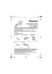
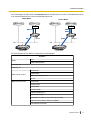
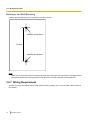
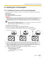
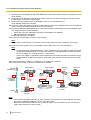
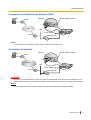
1
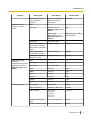
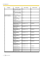
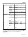
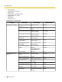
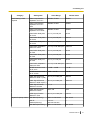
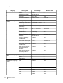
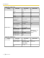
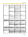
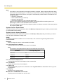
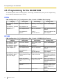
Installation Manual
E1 Trunk Adaptor/PRI Adaptor
Model No.
KX-NS8188
KX-NS8290
Thank you for purchasing this Panasonic product.
Please read this manual carefully before using this product and save this manual for future use.
Compatible PBX:
KX-NS1000 PCMPR Software File Version 002.00000 or later
Introduction
Introduction
This Installation Manual is designed to serve as an overall technical reference for the KX-NS8188 E1 Trunk
Adaptor/KX-NS8290 PRI Adaptor (Trunk Adaptor) for KX-NS1000. A Trunk Adaptor provides an E1/PRI trunk
interface to the KX-NS1000 and enables flexible trunk configuration. This manual provides instructions for
installing the hardware, and programming the Trunk Adaptor using Web Maintenance Console.
About the software version of your PBX
The contents of this manual apply to PBXs with a certain software version, as indicated on the cover of this
manual. Please confirm the software version of your PBX.
You can connect the Trunk Adaptor to the PBX without any activation keys.
Trademarks
• Microsoft, Internet Explorer, Windows and Windows Vista are either registered trademarks or trademarks
•
•
2
of Microsoft Corporation in the United States and/or other countries.
Mozilla and Firefox are registered trademarks of the Mozilla Foundation.
All other trademarks identified herein are the property of their respective owners.
Installation Manual
Table of Contents
Table of Contents
1 Safety Precautions ...................................................................................5
1.1
1.2
1.3
1.4
1.5
For Your Safety .................................................................................................................6
Important Safety Instructions ........................................................................................12
Precautions ......................................................................................................................13
Data Security ...................................................................................................................15
Additional Information ....................................................................................................16
2 System Outline .......................................................................................17
2.1
Basic System Construction ...........................................................................................18
2.1.1
Model Line-up .................................................................................................................18
2.1.2
Optional Equipment ........................................................................................................18
2.1.3
System Connection Diagram ..........................................................................................18
2.1.4
Service Feature ..............................................................................................................20
2.1.4.1
E1 Gateway .................................................................................................................20
2.1.4.2
PRI Gateway ...............................................................................................................20
2.2
Specifications ..................................................................................................................22
2.2.1
General Description ........................................................................................................22
2.2.2
System Capacity ............................................................................................................22
3 Installation ..............................................................................................23
3.1
3.2
3.2.1
3.2.2
3.2.3
3.2.4
3.2.5
3.2.6
3.2.7
3.3
3.3.1
Before Installation ...........................................................................................................24
Installation of the Trunk Adaptor ...................................................................................25
Unpacking ......................................................................................................................25
Names and Locations .....................................................................................................25
LED Indications ..............................................................................................................26
Types of Connectors ......................................................................................................27
Placing the Trunk Adaptor on a Desktop ........................................................................27
Wall Mounting .................................................................................................................28
Wiring Requirement ........................................................................................................30
Starting the Trunk Adaptor ............................................................................................31
Installation Procedure and Connection Diagrams ..........................................................31
4 Programming with Web Maintenance Console ...................................33
4.1
4.2
4.3
4.4
4.4.1
4.4.2
4.5
Overview of Web Maintenance Console .......................................................................34
PC Connection ................................................................................................................36
Starting Web Maintenance Console ..............................................................................38
Programming the Trunk Adaptor ...................................................................................39
Easy Setup Wizard .........................................................................................................39
Setting List ......................................................................................................................40
Programming for the KX-NS1000 ..................................................................................58
5 Troubleshooting .....................................................................................61
5.1
5.2
Installation .......................................................................................................................62
Error Messages ...............................................................................................................62
Index..............................................................................................................63
Installation Manual
3
Table of Contents
4
Installation Manual
Section 1
Safety Precautions
This section provides important information intended to
prevent personal injury and property damage.
Installation Manual
5
1.1 For Your Safety
1.1 For Your Safety
To prevent personal injury and/or damage to property, be sure to observe the following safety precautions.
The following symbols classify and describe the level of hazard and injury caused when this unit is
operated or handled improperly.
WARNING
This notice means that misuse could result in death
or serious injury.
CAUTION
This notice means that misuse could result in injury
or damage to property.
The following types of symbols are used to classify and describe the type of instructions to be
observed.
This symbol is used to alert users to a specific operating procedure that must not be performed.
This symbol is used to alert users to a specific operating procedure that must be followed in
order to operate the unit safely.
6
Installation Manual
1.1 For Your Safety
WARNING
•
•
•
•
•
•
•
•
•
•
•
•
•
•
•
•
•
•
Do not install the system in the following locations:
– Areas where shocks or vibrations are frequent or strong. Such activity may lead to the product falling
over and causing injury, or may impair the product’s performance.
– Areas with high amounts of dust. High amounts of dust can lead to fire or electric shock, and impair
the performance of the product.
Do not connect or disconnect the AC plug with wet hands.
Do not touch the Trunk Adaptor, AC adaptor or AC adaptor cord during a lightning storm.
Do not allow anything to rest on the AC adaptor cord or LAN cable. Do not locate the Trunk Adaptor where
the AC adaptor cord or LAN cable may be stepped on or tripped on.
When installing the Trunk Adaptor with an external AC adaptor, the AC adaptor should be plugged into a
wall outlet or floor-mounted AC outlet. Do not connect the AC adaptor to a ceiling-mounted AC outlet, as
the weight of the adaptor may cause it to become disconnected.
Make sure that you do not short the cables.
Never attempt to insert wires, pins, etc. into the vents or other holes of the Trunk Adaptor.
Do not splash water on the AC adaptor or the AC adaptor cord, nor get them wet. Doing so can result in
fire, electric shock, or injury. If they do get wet, immediately disconnect the AC adaptor, and contact an
authorised service centre.
Do not touch the AC adaptor for extended periods of time. Doing so can lead to low-degree burns.
Do not make power connections that exceed the ratings for the AC outlet or power equipment. If the power
rating is exceeded, it can cause a fire due to heat buildup.
Care should be taken so that objects do not fall onto, and liquids are not spilled into, the Trunk Adaptor.
Do not subject the Trunk Adaptor to excessive smoke, dust, moisture, mechanical vibration, shock, or direct
sunlight.
Do not place heavy objects on top of the Trunk Adaptor.
Do not mount the Trunk Adaptor in a manner other than that described in this manual.
The Trunk Adaptor must only be installed and serviced by qualified service personnel. The Trunk Adaptor
should be used as-is from the time of purchase; it should not be disassembled or modified. Disassembly
or modification can cause a fire, electric shock, or damage to the Trunk Adaptor.
Make sure that the wall that the Trunk Adaptor will be attached to is strong enough to support the Trunk
Adaptor (approx. 500 g). If not, it is necessary for the wall to be reinforced.
Only use the wall-mounting equipment (screws, washers) included with the Trunk Adaptor.
Be careful not to drop any components. Dropping components may damage them or cause an injury.
Disconnect the Trunk Adaptor from the AC outlet, disconnect the LAN cable, and contact the dealer if:
– The AC adaptor cord or AC plug becomes damaged or frayed.
– The Trunk Adaptor is exposed to rain, water, or any other liquid.
– The Trunk Adaptor is dropped or damaged.
– Internal components are exposed due to damage.
– The Trunk Adaptor does not operate properly.
– Performance deteriorates.
Installation Manual
7
1.1 For Your Safety
•
•
•
•
•
•
•
•
•
8
Disconnect the Trunk Adaptor from the AC outlet and disconnect the LAN cable if the Trunk Adaptor emits
smoke, an abnormal smell, or makes unusual noise. These conditions can cause fire or electric shock.
Confirm that smoke has stopped and contact an authorised service centre.
Clean the AC plug periodically with a soft, dry cloth to remove dust and other debris.
If using an AC adaptor, use only the optional AC adaptor KX-A239AL (PQLV206AL), KX-A239BX
(PQLV206CE), KX-A239CE (PQLV206CE), KX-A239EJ (PQLV206E), KX-A239UK (PQLV206E),
KX-A239X (PQLV206), or KX-A420BR (PSLP1662). Since the AC adaptors that can be used vary
depending on the country/area, contact an authorised service centre for details.
If damage to the Trunk Adaptor exposes any internal parts, immediately disconnect the cable or cord. If
the power is supplied from the network to the Trunk Adaptor (Power-over-Ethernet), disconnect the
Ethernet cables. Otherwise, disconnect the AC adaptor cord. Then return the Trunk Adaptor to a service
centre.
The Trunk Adaptor should only be connected to a power supply of the type shown on the label on the Trunk
Adaptor.
Completely insert the AC adaptor/power plug into the AC outlet. Failure to do so may cause electric shock
and/or excessive heat resulting in a fire.
When installing or testing a Trunk Adaptor with an external AC adaptor, the AC adaptor should be plugged
into a wall outlet or floor-mounted AC outlet. Do not connect the AC adaptor to a ceiling-mounted AC outlet,
as the weight of the adaptor may cause it to become disconnected.
The DC jack cover poses a choking hazard. Keep the DC jack cover out of reach of children.
When the Trunk Adaptor is no longer in use, make sure to detach it from the wall.
Installation Manual
1.1 For Your Safety
CAUTION
•
•
•
•
•
•
•
•
•
•
•
•
•
•
•
•
•
Do not install the system in the following locations:
– In direct sunlight and hot, cold, or humid places. (Temperature range: 0 °C to 40 °C)
– Areas where sulphuric gases may be present, such as near thermal springs.
– Near devices that generate high frequencies, such as sewing machines or electric welders.
– Locations where other objects will obstruct the area around the Trunk Adaptor. Be especially careful
to leave at least 5 cm to the sides of the Trunk Adaptor for ventilation.
Do not stretch or bend the cables. Also, do not allow anything to rest on the cables.
Do not bundle cables that are connected to the Trunk Adaptor with the AC power cords of machines located
nearby.
To prevent malfunction, deformity, overheating, rust, and discolouration, do not install or place equipment
in the following types of locations:
– Locations where air ventilation is poor.
– Locations that may be exposed to sulphurous gas, such as near hot springs.
– Near devices that emit heat, such as heaters.
– Near devices that emit electromagnetic noise, such as radios or televisions.
– Near devices that emit high-frequency noise, such as sewing machines or welders.
The Trunk Adaptor and the cables should never be placed near or over a radiator or other heat source.
The Trunk Adaptor should not be placed outdoors (use indoors).
The Trunk Adaptor should not be placed near high-voltage equipment.
The Trunk Adaptor should be kept free of dust, moisture, high temperature (more than 40 °C), low
temperature (less than 0 °C), and vibration, and should not be exposed to direct sunlight.
Before touching the product, discharge static electricity by touching ground or wearing an earthing strap.
Failure to do so may cause the Trunk Adaptor to malfunction due to static electricity.
When relocating the equipment, first disconnect the telecom connection before disconnecting the power
connection. When the unit is installed in the new location, reconnect the power first, and then reconnect
the telecom connection.
Make sure that the surface behind the Trunk Adaptor is not made of wood.
When driving the screws into the wall, be careful to avoid touching any metal laths, wire laths or metal
plates in the wall.
When mounting the Trunk Adaptor on a wall, be sure to run the cables down the side of the Trunk Adaptor.
Do not run the cables down the front of it.
When the Trunk Adaptor is placed on a desktop, make sure that the Trunk Adaptor is placed as indicated
in "3.2.5 Placing the Trunk Adaptor on a Desktop". Do not place it on its side or upside down.
When placing the Trunk Adaptor on a desktop, be sure to run the cables on the side of the Trunk Adaptor.
Do not run the cables on top or under it.
It is strongly recommended to use SSL encrypted communication when the PC is accessing the Trunk
Adaptor via the Internet. To use SSL encryption, routers must have a port set up for https communication.
Avoid using the same AC outlet for computers and other office equipment, as noise generated by such
equipment may hamper system performance or interrupt the system.
Installation Manual
9
1.1 For Your Safety
•
•
•
•
•
•
•
•
•
•
10
Unplug the system from its power source when wiring, and plug the system back in only after all wiring is
completed.
Use cables that are fire-resistant or fireproof.
Make sure the cables are securely fastened to the wall.
The AC adaptor is used as the main disconnect device. Ensure that the AC adaptor is located near the
Trunk Adaptor and is easily accessible.
Disconnect the AC adaptor cord and all cables from the Trunk Adaptor before cleaning. Clean the Trunk
Adaptor with a soft, dry cloth. Do not use liquid, aerosol cleaners, abrasive powders, or chemical agents
to clean the Trunk Adaptor.
When left unused for a long period of time, disconnect the Trunk Adaptor from the AC outlet. When the
Trunk Adaptor receives power from a PoE power supply, disconnect the LAN cable.
To ensure the security of private conversations, only connect the Trunk Adaptor to a secure network.
To prevent unauthorised access, only connect the Trunk Adaptor to a network that is properly managed.
Make sure all personal computers that are connected to the Trunk Adaptor employ up-to-date security
measures.
To avoid unauthorised access and possible abuse of your phone system, we strongly recommend:
– Keeping the password secret.
– Changing your password regularly.
– Selecting a complex, random password that cannot be easily guessed.
– Changing the installer password after logging in to Web Maintenance Console for the first time.
Installation Manual
1.1 For Your Safety
Notice
SAFETY REQUIREMENTS
• Before connecting the Trunk Adaptor, confirm that the Trunk Adaptor supports the intended operating
environment.
• If the Trunk Adaptor does not operate properly, disconnect the AC adaptor cord and LAN cable, then
connect again.
• The Trunk Adaptor may not operate in the event of a power failure.
• Do not move the Trunk Adaptor while it is in use.
• If you cannot make or receive calls, refer to the troubleshooting for this Trunk Adaptor or the PBX. If
the problem is not resolved, consult your dealer.
SECURITY REQUIREMENTS
• Keep a copy of all important data (such as your network information) before sending the machine for
repair.
• The Trunk Adaptor can store your private/confidential information. To protect your privacy/
confidentiality, we recommend that you initialise the Trunk Adaptor to erase all user data and restore
the factory default settings before you dispose, transfer or return the Trunk Adaptor.
Note
In this manual, the suffix of each model number (e.g., KX-NS8290CE) is omitted unless necessary.
Installation Manual
11
1.2 Important Safety Instructions
1.2 Important Safety Instructions
When using your telephone equipment, basic safety precautions should always be followed to reduce the risk
of fire, electric shock and injury to persons, including the following:
• Do not use the product near water, for example, near a bathtub, wash bowl, kitchen sink, or laundry tub,
in a wet basement, or near a swimming pool.
• Avoid using wired telephones during an electrical storm. There is a remote risk of electric shock from
lightning.
• Do not use a telephone in the vicinity of a gas leak to report the leak.
• Rack Mount Instructions—The following or similar rack-mount instructions are included with the installation
instructions:
Elevated Operating Ambient—If installed in a closed or multi-unit rack assembly, the operating ambient
temperature of the rack environment may be greater than room ambient. Therefore, consideration should
be given to installing the equipment in an environment compatible with the maximum ambient temperature
(Tma) specified by the manufacturer.
SAVE THESE INSTRUCTIONS
12
Installation Manual
1.3 Precautions
1.3 Precautions
For users in the European Union only
Information for Users on Collection and Disposal of Old Equipment and used Batteries
These symbols on the products, packaging, and/or accompanying documents mean that
used electrical and electronic products and batteries should not be mixed with general
household waste.
For proper treatment, recovery and recycling of old products and used batteries, please take
them to applicable collection points, in accordance with your national legislation and the
Directives 2002/96/EC and 2006/66/EC.
By disposing of these products and batteries correctly, you will help to save valuable
resources and prevent any potential negative effects on human health and the environment
which could otherwise arise from inappropriate waste handling.
For more information about collection and recycling of old products and batteries, please
contact your local municipality, your waste disposal service or the point of sale where you
purchased the items.
Penalties may be applicable for incorrect disposal of this waste, in accordance with national
legislation.
For business users in the European Union
If you wish to discard electrical and electronic equipment, please contact your dealer or
supplier for further information.
Information on Disposal in other Countries outside the European Union
These symbols are only valid in the European Union. If you wish to discard these items,
please contact your local authorities or dealer and ask for the correct method of disposal.
Note for the battery symbol (bottom two symbol examples):
This symbol might be used in combination with a chemical symbol. In this case it complies
with the requirement set by the Directive for the chemical involved.
For users in Germany only
• Machine Noise Information Ordinance, 3rd GPSGV: The highest sound pressure level is 70 dB (A) or less
•
according to EN ISO 7779.
This equipment is not for use at video display work stations according to BildscharbV.
For users in New Zealand only
• This equipment shall not be set to make automatic calls to the Telecom ‘111’ Emergency Service.
• The grant of a Telepermit for any item of terminal equipment indicates only that Telecom has accepted
•
•
that the item complies with minimum conditions for connection to its network. It indicates no endorsement
of the product by Telecom, nor does it provide any sort of warranty. Above all, it provides no assurance
that any item will work correctly in all respects with another item of Telepermitted equipment of a different
make or model, nor does it imply that any product is compatible with all of Telecom’s network services.
This equipment is not capable, under all operating conditions, of correct operation at the higher speeds for
which it is designed. Telecom will accept no responsibility should difficulties arise in such circumstances.
Using the toll services of a company other than Telecom:
If the PBX is set up to use the toll services of a company other than Telecom, the telephone numbers
dialled from the Caller Display listings within the PBX will be directed through the toll services of the other
Installation Manual
13
1.3 Precautions
•
•
14
company because the telephone numbers include the toll access digit and area code digit. A toll charge
may be incurred. Please check with the toll carrier concerned.
APPLICABLE ONLY TO TELECOM CUSTOMERS WHO HAVE AUTOMATIC ACCESS TO OTHER
CARRIERS FOR TOLL CALLS
When calling back a number from the Caller ID list, all numbers prefixed with "0 + AREA CODE" will be
automatically forwarded to your toll carrier. This includes numbers in your local calling area. The zero +
area code should either be removed when calling back local numbers, or check with your toll carrier that
a charge will not be levied.
All persons using this device for recording telephone conversations shall comply with New Zealand law.
This requires that at least one party to the conversation is to be aware that it is being recorded. In addition,
the principles enumerated in the Privacy Act 1993 shall be complied with in respect to the nature of the
personal information collected, the purpose for its collection, how it is used, and what is disclosed to any
other party.
Installation Manual
1.4 Data Security
1.4 Data Security
In order to use the Trunk Adaptor safely and correctly, the Security Requirements below must be observed.
Failure to do so may result in loss, leakage, falsification or theft of user information.
What is User Information?
User Information is defined as system data and error data information stored on the Trunk Adaptor.
Requirements
1. To prevent illegal access from the Internet, activate a Firewall.
2. To avoid unauthorised access and possible abuse of the Trunk Adaptor, we strongly recommend:
a. Keeping the password secret.
b. Selecting a complex, random password that cannot be easily guessed.
c. Changing your password regularly.
3. When user information is sent from the Trunk Adaptor to a PC, the confidentiality of that information
becomes the responsibility of the customer. Before disposing of the PC, ensure that data cannot be
retrieved from it by formatting the hard disk and/or rendering it physically unusable.
Installation Manual
15
1.5 Additional Information
1.5 Additional Information
For Users in Canada Only
This product meets the applicable Industry Canada technical specifications.
This Class A digital apparatus complies with Canadian ICES-003.
Notice
Attachment of non-IC certified/registered equipment is illegal in some areas of Canada. Please consult
your Telephone Company.
CAUTION
Users should not attempt to make such connections themselves, but should contact the appropriate electric
inspection authority, or electrician, as appropriate.
16
Installation Manual
Section 2
System Outline
This section provides general information on the Trunk
Adaptor, including the system capacity and
specifications.
Installation Manual
17
2.1.3 System Connection Diagram
2.1 Basic System Construction
2.1.1 Model Line-up
The following table shows the different types of Trunk Adaptor.
Type
Model No.
KX-NS8188X
E1 Trunk Adaptor
KX-NS8290CE
PRI Adaptor (30 ch)
KX-NS8290X
PRI Adaptor (23 ch)
2.1.2 Optional Equipment
AC Adaptor
•
•
•
•
•
•
•
KX-A239AL (PQLV206AL)
KX-A239BX (PQLV206CE)
KX-A239CE (PQLV206CE)
KX-A239EJ (PQLV206E)
KX-A239UK (PQLV206E)
KX-A239X (PQLV206)
KX-A420BR (PSLP1662)
Note
To order an optional AC adaptor, please order using the "KX-A239xx/KX-A420BR" model number (not
"PQLV206xx/PSLP1662"). For users in Argentina, power can only be supplied by PoE.
2.1.3 System Connection Diagram
The following diagram shows the connection configuration image of a system containing a KX-NS8188/
KX-NS8290. Multiple Trunk Adaptors can be connected to one KX-NS1000.
18
Installation Manual
2.1.3 System Connection Diagram
Note
You can connect the Trunk Adaptor to the PBX without the need for activation keys.
LAN
E1 Trunk Adaptor (KX-NS8188)/
PRI Adaptor (KX-NS8290)
Pure IP-PBX
(KX-NS1000)
E1/PRI
(23 ch/30 ch)
DSU*1
SIP Phone
(KX-UT series)
Telephone
Company
IP-PT
(KX-NT series)
PC (Web
Maintenance Console)
*1
DSU: Digital Service Unit
Installation Manual
19
2.1.4 Service Feature
2.1.4 Service Feature
2.1.4.1 E1 Gateway
The Trunk Adaptor for E1 trunks allows a KX-NS1000 to connect to an E1 line as it converts data between the
SIP and E1 protocols.
PSTN
IP Network
DSU
E1 Line
E1 Trunk
Adaptor
SIP
LAN
KX-NS1000
The following table shows features supported by the E1 Trunk Adaptor.
Note that the private network feature is not available.
Features
Signalling
Dial type
DR2
MFC-R2
DTMF
Incoming call
Outgoing call
Caller Number Notification (ANI)
Deny collect call for Brazil
Outgoing call auto disconnect
2.1.4.2 PRI Gateway
The Trunk Adaptor for PRI Trunks—Public Mode allows a KX-NS1000 to connect to a PRI line as it converts
data between the SIP and ISDN protocols.
20
Installation Manual
2.1.4 Service Feature
The Trunk Adaptor for PRI Trunks—Private Mode allows a KX-NS1000 to connect to a PRI QSIG network as
it converts data between the H.323 and ISDN QSIG protocols.
Public Mode
Private Mode
IP Network
IP Network
PSTN
Private Network
DSU
DSU
ISDN
QSIG
PRI Line
PRI
Adaptor
SIP
LAN
H.323
PRI
Adaptor
LAN
KX-NS1000
KX-NS1000
The following table shows features supported by the PRI Adaptor.
Features
Mode
CO
QSIG-Master/Slave
Incoming call
Outgoing call
CLIP/CLIR
ISDN carrier service
CNIP/CNIR
Advice of Charge (AOC)
E-911
QSIG private service
CLIP/CLIR
COLP/COLR
CNIP/CNIR
CONP/CONR
Call Forwarding (CF)
Call Transfer (CT)
Completion of Calls to Busy Subscriber (CCBS)
Network Direct Station Selection (NDSS)
Centralised Voice Mail
Installation Manual
21
2.2.2 System Capacity
2.2 Specifications
2.2.1 General Description
CPU
ARM11 450 MHz
Network port
1 port (RJ45 connector)
IEEE802.3 10/100BASE-TX
Auto Negotiation, Auto MDI/MDI-X
Status LED: LINK, 100
Line interface
1 port (RJ45 connector)
Framer
E1/T1 framer
NT/TE mode
E1/PRI Public mode: TE
QSIG Master: TE
QSIG Slave: NT
Loop back mode
Local loop back, Remote loop back
System Initialise switch
Push switch (non-latching)
Power consumption
PoE: Maximum 6.4 W
AC adaptor: Maximum 6.75 W
Power over Ethernet
IEEE 802.3af Class 2
Dimension
210 mm (W) ´ 44 mm (H) ´ 150 mm (D)
Weight
500 g
Temperature
0 °C to 40 °C
Humidity
10 % – 90 % RH
2.2.2 System Capacity
Maximum Channel Number
Model No.
PBX Connection
Trunk Connection
KX-NS8188X
30 ch
30 ch
KX-NS8290CE
30 ch
30 ch
KX-NS8290X
23 ch
23 ch
22
Installation Manual
Section 3
Installation
This section describes the procedures to connect the
Trunk Adaptor to the PBX.
Installation Manual
23
3.1 Before Installation
3.1 Before Installation
Please read the following notes concerning installation and connection before installing the Trunk Adaptor. Be
sure to comply with all applicable laws, regulations, and guidelines.
Notice
Panasonic assumes no responsibility for injuries or property damage resulting from failures arising out of
improper installation or operation inconsistent with this documentation.
Installation Precautions
The Trunk Adaptor can be mounted on a wall or placed on a desktop, and should be installed in a location
where it is accessible for inspections and maintenance.
To prevent malfunction, noise, or discolouration, follow the instructions below:
WARNING
Do not install the system in the following locations:
• Areas where shocks or vibrations are frequent or strong. Such activity may lead to the product
falling over and causing injury, or may impair the product’s performance.
• Areas with high amounts of dust. High amounts of dust can lead to fire or electric shock, and
impair the performance of the product.
CAUTION
Do not install the system in the following locations:
• In direct sunlight and hot, cold, or humid places. (Temperature range: 0 °C to 40 °C)
• Areas where sulphuric gases may be present, such as near thermal springs.
• Near devices that generate high frequencies, such as sewing machines or electric welders.
• Locations where other objects will obstruct the area around the Trunk Adaptor. Be especially careful
to leave at least 5 cm to the sides of the Trunk Adaptor for ventilation.
Notice
Do not install the system in the following locations:
• On or near computers, or other office equipment, as well as microwave ovens or air conditioners. (It is
preferable not to install the system in the same room as the above equipment.)
• Within 1.8 m of radios and televisions. (Both the Trunk Adaptor and the PBX should be at least 1.8 m
away from such devices.)
Wiring Precautions
Be sure to follow these instructions when wiring the unit:
CAUTION
•
•
24
Avoid using the same AC outlet for computers and other office equipment, as noise generated by such
equipment may hamper system performance or interrupt the system.
Unplug the system from its power source when wiring, and plug the system back in only after all wiring
is completed.
Installation Manual
3.2.2 Names and Locations
3.2 Installation of the Trunk Adaptor
3.2.1 Unpacking
Unpack the box and check the items below:
Main Unit ´ 1
Screw ´ 2
Washer ´ 2
Notice
After unpacking the product, dispose of the packing materials appropriately.
3.2.2 Names and Locations
Front Side
Front Side when Wall Mounted
AB
Back Side
C DE
FG H
No.
Name
Description
A
SYSTEM LED
System operating status indication
B
LINE LED
Alarm, synchronisation, and data link status indication
C
DC Jack (9V)
DC input terminal
D
LAN Port
Ethernet interface
E
LAN LED (LINK)
Ethernet link status indication
Installation Manual
25
3.2.3 LED Indications
No.
Name
Description
F
LAN LED (100)
Ethernet data transmission speed indication
G
LINE Port
E1 line interface (KX-NS8188X)
PRI23 line interface (KX-NS8290X)
PRI30 line interface (KX-NS8290CE)
H
INITIALIZE
System Initialise switch
3.2.3 LED Indications
Status
Indication
SYSTEM
Power off
Off
Awaiting system initialisation
Quick Amber Flashing (5 s)
Pushing the System Initialise switch
Off (2 s) ® Amber On
Starting up
Before starting Linux
Amber On
After starting Linux*1
Slow Amber Flashing
Awaiting Easy Setup
Slow Green Flashing
Running (In Service)
Green On
System initialisation
failed
Quick Red Flashing
Starting up
completed
LINE
LAN
LINK
100
*1
*2
Malfunction occurring (Fault)*2
Red On
Halting operation (Out of Service)
Amber On
Shutting down
Slow Amber Flashing ® Amber On
Not Running (Out of Service/Fault)
Off
Running (In Service)—all ports are idle
Green On
Running (In Service)—a port is in use
Slow Green Flashing
Off-line
Off
Linked normally
Green On
Communicating
Green Flashing
Data transmission speed: 10 Mbps
Off
Data transmission speed: 100 Mbps
Yellow On
The LED flashes amber for about one minute.
Faults can be caused by the following:
•
•
•
26
Colour
There is a problem with the Trunk Adaptor.
There is a problem with the PRI/E1 line, such as a disconnected cable.
An E1 port with DR2 set as the Channel Type does not exist. (See "4.4.2 Setting List—Configuration—Trunk Interface".)
Installation Manual
3.2.5 Placing the Trunk Adaptor on a Desktop
Note
•
•
LED flashing patterns are as follows:
– Slow Flashing: 60 times per minute
– Quick Flashing: 240 times per minute
For information about LED indications when performing a program update, see "4.4.2 Setting List—
System Control—Program Update".
3.2.4 Types of Connectors
Please refer to "Types of Connectors" in the Installation Manual of the KX-NS1000 PBX. The connector type
for the Trunk Adaptor is RJ45.
3.2.5 Placing the Trunk Adaptor on a Desktop
When placing the Trunk Adaptor on a desktop, make sure to follow these instructions.
WARNING
Be careful not to drop any components. Dropping components may damage them or cause an
injury.
CAUTION
•
When the Trunk Adaptor is placed on a desktop, make sure that it is placed as indicated in the diagram
below. Do not place it on its side or upside down.
Desk or Table
•
When placing the Trunk Adaptor on a desktop, be sure to run the cables on the side of the Trunk
Adaptor. Do not run the cables on top or under it. The following illustrations are bad examples of cable
wiring.
Installation Manual
27
3.2.6 Wall Mounting
3.2.6 Wall Mounting
The Trunk Adaptor can be mounted on a concrete wall using the wall-mounting equipment (screws, washers).
WARNING
•
•
•
•
Make sure that the wall that the Trunk Adaptor will be attached to is strong enough to support
the Trunk Adaptor (approx. 500 g). If not, it is necessary for the wall to be reinforced.
Only use the wall-mounting equipment (screws, washers) included with the Trunk Adaptor.
Be careful not to drop any components. Dropping components may damage them or cause an
injury.
When the Trunk Adaptor is no longer in use, make sure to detach it from the wall.
CAUTION
•
•
•
•
•
•
•
•
Make sure that the surface behind the Trunk Adaptor is not made of wood.
When driving the screws into the wall, be careful to avoid touching any metal laths, wire laths or plates
in the wall.
Do not stretch or bend the cables. Also, do not allow anything to rest on the cables.
Use cables that are fire-resistant or fireproof.
The Trunk Adaptor and the cables should never be placed near or over a radiator or other heat source.
Do not bundle cables that are connected to the Trunk Adaptor with the AC power cords of machines
located nearby.
Make sure the cables are securely fastened to the wall.
When mounting the Trunk Adaptor on a wall, be sure to run the cables down the side of the Trunk
Adaptor. Do not run the cables down the front of it. The following illustration is a bad example of cable
wiring.
Note
For details about the dimensions and weight of the Trunk Adaptor, see "2.2.1 General Description".
Necessary Items (included)
Screw ´ 2
Washer ´ 2
28
Installation Manual
3.2.6 Wall Mounting
Wall Mounting Procedure
1. Place the reference for wall mounting on the wall to mark the 2 screw positions.
2. Install the 2 screws and washers (included) into the wall.
Note
•
•
Make sure that the screw heads are at the same distance from the wall.
Install the screws perpendicular to the wall.
3. Hook the Trunk Adaptor on the screw heads in any of the following 4 directions.
A
Hook this part onto
both screws.
Washer
Drive the screw
to this point.
B
C
D
Installation Manual
29
3.2.7 Wiring Requirement
Reference for Wall Mounting
Please copy this page and use as a reference for wall mounting.
Install a screw here.
83 mm
Install a screw here.
Note
Make sure to set the print size to correspond with the size of this page. If the dimension of the paper output
still deviates slightly from the measurement indicated here, use the measurement indicated here.
3.2.7 Wiring Requirement
Be sure to run the LAN cables of the E1/PRI network inside a building. Do not run the LAN cables outside of
the building.
30
Installation Manual
3.3.1 Installation Procedure and Connection Diagrams
3.3 Starting the Trunk Adaptor
3.3.1 Installation Procedure and Connection Diagrams
This section describes the installation procedure for connecting the Trunk Adaptor and KX-NS1000 PBX.
Requirements
Power supply: AC adaptor
Trunk Adaptor IP address: Static IP address
WARNING
When installing or testing a Trunk Adaptor with an external AC adaptor, the AC adaptor should be
plugged into a wall outlet or floor-mounted AC outlet. Do not connect the AC adaptor to a
ceiling-mounted AC outlet, as the weight of the adaptor may cause it to become disconnected.
Note
•
•
Use only the optional AC adaptor KX-A239 for the Trunk Adaptor. For details about the optional AC
adaptor, refer to "2.1.2 Optional Equipment".
When receiving power using PoE, the AC adaptor is not necessary.
The installation process is as follows:
1. Obtain the Trunk adaptor’s IP address from the network manager.
2. Connect a PC to the Trunk Adaptor with a LAN cable. (See "4.2 PC Connection".)
3. Connect an AC adaptor to the Trunk Adaptor ensuring that it is hooked as shown below.
DC Jack Cover
To AC Adaptor
4. Press and hold the System Initialise switch for more than one second before the SYSTEM LED stops
flashing. The system settings of the Trunk Adaptor will be returned to factory default settings.
5. When the SYSTEM LED flashes green slowly, set the PC to static IP address mode, enter the Trunk
Adaptor’s IP address (default: 192.168.0.151) into the PC’s Web browser, and then login to the Trunk
Adaptor’s Web Maintenance Console. (See "4.4.1 Easy Setup Wizard".)
6. Configure the Trunk Adaptor’s settings to specify the following. (See "4.4.2 Setting List".)
• Static IP address for the Trunk Adaptor
• SIP/H.323 connection parameters
– SIP: ID & Password
– H.323: Static IP address for KX-NS1000
• PRI/E1 parameters
Installation Manual
31
3.3.1 Installation Procedure and Connection Diagrams
7. Shutdown the Trunk Adaptor through Web Maintenance Console and disconnect the AC adaptor from the
Trunk Adaptor.
8. Change the Trunk Adaptor’s LAN cable connection from the PC to the switching hub, and then connect
the AC adaptor to the Trunk Adaptor again.
9. Confirm the running status of the Trunk Adaptor. (See "3.2.3 LED Indications".)
Trunk Adaptor settings are complete.
10. Connect the PC to the switching hub with a LAN cable and obtain the IP address of the PC from the DHCP
server, or set the IP address manually and connect to the PC.
11. Log in to KX-NS1000’s Web Maintenance Console and configure the following for the Trunk Adaptor. (See
"4.5 Programming for the KX-NS1000".)
• SIP/H.323 connection parameters (including Trunk Adaptor’s IP address)
• DDI call distribution settings etc.
KX-NS1000 settings are complete.
12. Connect the Trunk Adaptor to the E1 or PRI network.
Note
The cable connecting the Trunk Adaptor to the network should be CAT 5 (Category 5) or higher.
13. Confirm the running status of the Trunk Adaptor (LINE LED). (See "3.2.3 LED Indications".)
Note
•
•
If connecting to the KX-NS1000 via SIP, confirm that the SIP trunk port status is "INS" through the
KX-NS1000’s Web Maintenance Console. SIP connection and registration is possible only when
the Trunk Adaptor is connected to the E1 or PRI network.
If the Trunk Adaptor is restarted or disconnected from the network and then reconnected, even if
the SYSTEM and LINE LEDs are green, it may take some minutes until all channels are in "INS"
status.
14. Confirm that making a call from an extension to an outside line is possible.
15. Confirm that receiving a call from an outside line is possible.
Trunk Adaptor
Network
Administrator
1
Trunk Adaptor
8
4
To AC
Adaptor
Obtain Trunk
Adaptor’s
IP Address
3
To AC
Adaptor
12 - 13
2
SIP Phone
14 - 15
9
10 - 11
DSU
E1/PRI
Network
5-7
Installer
Switching
Hub
Web Maintenance
Console
KX-NS1000
Web Maintenance
Console
Note
•
•
32
Use an Ethernet straight cable with an RJ45 connector for connection to a switching hub. The cable
should be a 10BASE-T/100BASE-TX CAT 5 or higher cable.
Make sure that all cables used are CAT 5 cables or higher, and LAN cables are 100 m or less and
LINE cables are 200 m or less in length.
Installation Manual
Section 4
Programming with Web Maintenance Console
This section describes the installation procedure,
structure, and functions of Web Maintenance Console
for programming the Trunk Adaptor.
Installation Manual
33
4.1 Overview of Web Maintenance Console
4.1 Overview of Web Maintenance Console
Web Maintenance Console of the Trunk Adaptor is designed to serve as an overall system programming
reference for the Trunk Adaptor. You can programme and control the Trunk Adaptor over an IP network using
Web Maintenance Console.
This section describes programming basic items using Web Maintenance Console.
The screen below shows the home screen of Web Maintenance Console for the Trunk Adaptor.
Note
•
•
The contents and design of the software are subject to change without notice.
It is also possible to access Web Maintenance Console for the Trunk Adaptor using the KX-NS1000
Web Maintenance Console. For details about the KX-NS1000 Web Maintenance Console, refer to
"Overview of Web Maintenance Console" in the Installation Manual of the KX-NS1000 PBX.
The settings on the screen are as follows:
Setting Item
34
Description
Value Range
SYSTEM
Displays the status of the system.
INS (In Service)
OUS (Out of Service)
Fault
LINE
Displays the status of the E1 line or PRI line.
INS
OUS
Adaptor Name
Displays the name set in Easy Setup—Adaptor
Setting. You can change the name here, and then
click [OK], if required.
Max. 32 characters
LINE Status
Displays error messages related to the line. (See
"5.2 Error Messages".)
INS, Error message
IP Address
Displays the Trunk Adaptor’s IP address.
1.0.0.0–223.255.255.255
MAC Address
Displays the Trunk Adaptor’s MAC address.
00:00:00:00:00:00–
FF:FF:FF:FF:FF:FF
Installation Manual
4.1 Overview of Web Maintenance Console
Setting Item
Software Version
Description
Displays the Trunk Adaptor’s software version.
Value Range
000.000.00–999.999.99
Installation Manual
35
4.2 PC Connection
4.2 PC Connection
You can connect a PC to the Trunk Adaptor either directly or over a LAN using the appropriate method for the
port being used.
Direct Connection
LAN Port
System Initialise Switch
To LAN Port
To AC Adaptor
Notice
When connecting a PC to the Trunk Adaptor, a fixed IP address must be assigned to the PC. For information
about fixed IP addresses, ask your network administrator.
Note
•
•
Use an Ethernet cable with an RJ45 connector to connect a PC to the Trunk Adaptor.
The pin assignments and maximum cabling distance are the same as when connecting a PC to the
MNT port of the KX-NS1000. Please refer to "Connection of Peripherals" in the Installation Manual of
the KX-NS1000 PBX.
Connection via LAN
LAN Port
LAN
PC
36
Installation Manual
Switching Hub
To AC Adaptor
System Initialise Switch
4.2 PC Connection
Connection via Virtual Private Network (VPN)
PC
LAN Port
System Initialise Switch
Router
VPN
LAN
To AC Adaptor
Router
Switching Hub
Notice
To access the Trunk Adaptor via VPN, the PC must be in the same VPN.
Connection via Internet
PC
LAN Port
System Initialise Switch
Router
Internet
LAN
To AC Adaptor
Router
Switching Hub
CAUTION
It is strongly recommended to use SSL encrypted communication when the PC is accessing the Trunk
Adaptor via the Internet. To use SSL encryption, routers must have a port set up for https communication.
Notice
To access the PBX via the internet, routers must have static NAT/NAPT settings enabled.
Installation Manual
37
4.3 Starting Web Maintenance Console
4.3 Starting Web Maintenance Console
System Requirements
Required Operating System
• Microsoft® Windows® XP, Windows Vista® Business, or Windows 7 Professional operating system
Recommended Display Settings
• Screen resolution: XGA (1024 ´ 768)
• DPI setting: Normal size (96 DPI)
Supported Browsers for use with Web Maintenance Console
• Windows Internet Explorer® 8
• Windows Internet Explorer 9
• Mozilla® Firefox® version 6 or later
Note
Always be sure to apply the latest updates to your Web browser software. For details, refer to your Web
browser’s documentation. Only the browsers and browser versions listed above are supported for use with
Web Maintenance Console.
Copyright for MD5
This software uses the Source Code of RSA Data Security, Inc. described in the RFC1321 (MD5
Message-Digest Algorithm).
Copyright (C) 1991-2, RSA Data Security, Inc. Created 1991. All rights reserved.
Licence to copy and use this software is granted provided that it is identified as the "RSA Data Security, Inc.
MD5 Message-Digest Algorithm" in all material mentioning or referencing this software or this function.
Licence is also granted to make and use derivative works provided that such works are identified as "derived
from the RSA Data Security, Inc. MD5 Message-Digest Algorithm" in all material mentioning or referencing the
derived work.
RSA Data Security, Inc. makes no representations concerning either the merchantability of this software or
the suitability of this software for any particular purpose. It is provided "as is" without express or implied warranty
of any kind.
These notices must be retained in any copies of any part of this documentation and/or software.
Password Security
Please refer to "Starting Web Maintenance Console" in the Installation Manual of the KX-NS1000 PBX.
38
Installation Manual
4.4.1 Easy Setup Wizard
4.4 Programming the Trunk Adaptor
4.4.1 Easy Setup Wizard
In the Easy Setup Wizard, you will set up the mandatory settings required for the Trunk Adaptor.
When you log in to Web Maintenance Console for a Trunk Adaptor that is in its initialised, factory default state,
the Easy Setup Wizard will launch automatically. Log in using the following account name and password.
– The account name is "INSTALLER".
– The default account password is "1234".
1. After Easy Setup Wizard launches, select a language, and then click Install.
2. In Location and Configuration Setting:
a. Select the Suffix Code of KX-NS1000 from the drop-down list for the PBX you are connecting to.
Note
If Suffix Code of KX-NS1000 is changed from its default value, a notice about restarting the Trunk
Adaptor is displayed. Click OK to restart the Trunk Adaptor. After the Trunk Adaptor restarts, start
Web Maintenance Console again (refer to "Starting Web Maintenance Console" in the Installation
Manual of the KX-NS1000 PBX). When you start the Easy Setup Wizard again, you will start from
step 3, below.
b. Select the Area of KX-NS1000 from the drop-down list for the PBX you are connecting to.
c. [KX-NS8290 only]
Select a Network Type from the drop-down list (Public or Private).
d. Specify SIP Authentication ID Plan, which is the header digits of the SIP authentication ID for
connecting to a KX-NS1000 SIP trunk.
For example, if "4" (default) is set, numbers 401–430 are registered as the SIP authentication ID for
SIP ports 1–30.
Note
When Private is selected for the Network Type, this setting is skipped.
3. In Adaptor Setting:
a. Specify an Adaptor Name.
b. Select a Time Zone from the drop-down list.
c. Click Next.
4. In LAN Setting, the IP addresses for the Trunk Adaptor and DNS server can be assigned automatically
through a DHCP server or entered manually.
When using a DHCP server:
a. Select Obtain an IP address automatically.
b. Select Obtain DNS server address automatically.
Notice
The boxes will turn grey and the IP address information will be assigned automatically.
Write down the address information assigned to the Trunk Adaptor for future reference.
c. Click Next.
When not using a DHCP server:
a. Select Use the following IP address.
b. Enter an IP address*1, Subnet Mask*2, and Default Gateway*1. (The default gateway may not need to
be specified depending on your network configuration.)
c. Select Use the following DNS server address.
Installation Manual
39
4.4.2 Setting List
d. Enter the preferred and alternative DNS IP addresses*1.
e. Click Next.
*1
*2
Valid IP address range: "1.0.0.0" to "223.255.255.255"
Valid subnet mask address range: "0–255.0–255.0–255.0–255" (except "0.0.0.0" and "255.255.255.255")
5. In SNTP / Daylight Saving, enter information for Automatic Time Adjustment and Daylight Saving, and
then click Next.
6. In Maintenance Setting, enter a password in Installer password, confirm your input in Re-enter, and
then click Finish.
If LAN settings have been changed from their default values in step 4, you will be prompted to restart the
Trunk Adaptor. Click OK to restart the Trunk Adaptor.
7. After the Trunk Adaptor restarts, log in using the password entered during Easy Setup Wizard.
The home screen is displayed. You may now begin programming the Trunk Adaptor.
4.4.2 Setting List
The following tables show the settings (items, value ranges, and defaults etc.) that you can configure using
Web Maintenance Console for the Trunk Adaptor.
Configuration—Trunk Interface
Setting Item
Category
PRI23/PRI30 Card
Property
40
Installation Manual
Value Range
Default Value
T200
0–600
10
T202
0–600
20
T203
0–600
100
T301
0–18000
0
T302
0–600
150
T303
0–600
40
T304
0–3000
300
T305
0–3000
300
T308
0–600
40
T309
0–3000
120
T310
0–3000
1100
T313
0–600
40
T316
0–3000
0
T318
0–600
0
T319
0–600
0
T322
0–600
40
T3D3
0–3000
100
T3D9
0–3000
200
Network CODEC
G.711A, G.711Mu
KX-NS8290X: G.711Mu
KX-NS8290CE: G.711A
4.4.2 Setting List
Category
PRI23/PRI30 Port
Property—Main
PRI23/PRI30 Port
Property—CO Setting
Setting Item
Value Range
Default Value
Incoming Call Inter-digit
Timer - DDI/DID
0–30 s
5s
Incoming Call Inter-digit
Timer - TIE
3–30 s
5s
Port
1
–
Port Type
CO (fixed when
Network Type is set to
Public)
CO
QSIG-Slave,
QSIG-Master (when
Network Type is set to
Private)
Set during "4.4.1 Easy
Setup Wizard"
Connection
INS, OUS, Fault
–
Status Message
No Transmission, When
error detection
(Mandatory), When
error detection (Option /
Mandatory)
No Transmission
Status Receive
Ignore, Disconnect
Ignore
CRC4 Mode
Disable, Enable
Enable
Line Coding
B8ZS, AMI
B8ZS
Frame Sequence
Extended Multi frame
(ESF), 4-Frame Multi
frame (F4), 12-Frame
Multi frame (F12)
Extended Multi frame
(ESF)
Port
1
–
Port Type
CO (fixed when
Network Type is set to
Public)
CO
QSIG-Slave,
QSIG-Master (when
Network Type is set to
Private)
Set during "4.4.1 Easy
Setup Wizard"
Connection
INS, OUS, Fault
–
Ringback Tone to
Outside Caller
Disable, Enable
Disable
ISDN Outgoing Call
Type
En-bloc, Overlap
Overlap
Networking Data
Transfer
Off, On
On
Installation Manual
41
4.4.2 Setting List
Category
PRI23/PRI30 Port
Property—Network
Configuration
PRI23/PRI30 Port
Property—Network
Numbering Plan
42
Installation Manual
Setting Item
Value Range
Default Value
Port
1
–
Port Type
CO (fixed when
Network Type is set to
Public)
CO
QSIG-Slave,
QSIG-Master (when
Network Type is set to
Private)
Set during "4.4.1 Easy
Setup Wizard"
Connection
INS, OUS, Fault
–
Network Type
0–56
–
Port
1
–
Port Type
CO (fixed when
Network Type is set to
Public)
CO
QSIG-Slave,
QSIG-Master (when
Network Type is set to
Private)
Set during "4.4.1 Easy
Setup Wizard"
Connection
INS, OUS, Fault
–
Calling Party Number—
Numbering Plan ID
(Public)
Unknown,
ISDN-Telephony,
National Standard,
Private
Unknown
Calling Party Number—
Numbering Plan ID
(Private)
Unknown,
ISDN-Telephony,
National Standard,
Private
Private
Calling Party Number—
Type of Number (Public)
Unknown, International,
National, Network,
Subscriber
Subscriber
Calling Party Number—
Type of Number
(Private)
Unknown, International,
National, Network,
Subscriber
Unknown
Called Party Number—
Numbering Plan ID
(Public)
Unknown,
ISDN-Telephony,
National Standard,
Private
Unknown
Called Party Number—
Numbering Plan ID
(Private)
Unknown,
ISDN-Telephony,
National Standard,
Private
Private
Called Party Number—
Type of Number (Public)
Unknown, International,
National, Network,
Subscriber
Unknown
4.4.2 Setting List
Category
PRI23/PRI30 Port
Property—System
Option
PRI23/PRI30 Port
Property—
Supplementary Service
(Displayed only when
Network Type is set to
Public.)
E1 Card Property
Setting Item
Value Range
Default Value
Called Party Number—
Type of Number
(Private)
Unknown, International,
National, Network,
Subscriber
Unknown
Port
1
–
Port Type
CO (fixed when
Network Type is set to
Public)
CO
QSIG-Slave,
QSIG-Master (when
Network Type is set to
Private)
Set during "4.4.1 Easy
Setup Wizard"
Connection
INS, OUS, Fault
–
ISDN Voice Path
Connection—Connect
when "Alert" is sent from
ISDN
Enable, Disable
Disable
Calling Party Name
Presentation to PRI23
Enable, Disable
Disable
Calling Party Name
Sending Format
Display, Facility
Display
Port
1
–
Port Type
CO (fixed)
CO
Connection
INS, OUS, Fault
–
CLIR
Yes, No
Yes
CNIP
Yes, No
Yes
CNIR
Yes, No
Yes
AOC-D
Yes, No
Yes
AOC-E
Yes, No
Yes
E911
Yes, No
Yes
Line Coding
HDB3, AMI
HDB3
Frame Sequence
PCM30, PCM30-CRC
PCM30
Frame Option
C=A, D=B
C=0, D=0
C=0, D=1
C=1, D=0
C=1, D=1
C=0, D=1
First Dial Timer (DDI /
DID)
32 × n (n=1–255) ms
64 ms
Answer Detection Timer
32 × n (n=1–255) ms
32 ms
Installation Manual
43
4.4.2 Setting List
Category
E1 Card Property—Line
Signal Setting
44
Installation Manual
Setting Item
Value Range
Default Value
Seizure ACK Wait Timer
0.5 × n (n=1–20) s
2.5 s
LIU Send Option
Mode-1 – Mode-8
Mode-8
LIU Receive Option
Automatic, 6 dB, 12 dB,
18 dB, 24 dB
Automatic
RAI Signal Detection
Mode
Type1, Type2
Type1
DTMF Tone—DTMF
Inter-digit Pause
16 × n (n=4–15) ms
112 ms
Collect Call Reject (for
Brazil)—Mode
Enable, Disable
Disable
Collect Call Reject (for
Brazil)—Wait Time
500 ms, 1000 ms,
1500 ms, 2000 ms
1000 ms
Collect Call Reject (for
Brazil)—Flashing Time
1000 ms, 1500 ms,
2000 ms, 2500 ms
2000 ms
Network CODEC
G.711A, G.711Mu
G.711A
Incoming Call Inter-digit
Timer - DDI/DID
0–30 s
5s
DR2 Setting Type
Normal, Option-1,
Option-3
Normal
Inter-digit Timer
3–15 s
4s
Bit Position for Dial
Flash
A-bit, B-bit
A-bit
Bit Position for Clear
Back
A-bit, B-bit, A&B-bit
A-bit
Forced Release
Disable, Enable
Enable
Forced Release Pattern
A=0/B=0
A=0/B=1
A=1/B=0
A=1/B=1
A=1/B=0
DSP Gain Adjustment—
DTMF Transmit
3 – -12 dB
-3 dB
DSP Gain Adjustment—
DTMF Receive
(-42 – 0 dB) – (-11 –
0 dB)
-26 – 0 dB
DSP Gain Adjustment—
MFC-R2 Transmit
0 – -31 dB
-16 dB
DSP Gain Adjustment—
MFC-R2 Receive
(-38 – 0 dB) – (-23 –
0 dB)
-30 – 0 dB
Frame Error Detection—
Error Detection
No, Yes
No
Frame Error Detection—
Error Rate
No limit, 16 × n (n=1–7)
errors/s
No limit
4.4.2 Setting List
Category
E1 Card Property—
MFC-R2 Setting 1
Setting Item
Value Range
Default Value
ANI Service—Mode
None, Incoming call
only, Outgoing call only,
Both calls
None
ANI Service—ANI Max.
digits
None, 1–16
None
MFC-R2 Timer—
Forward
1–30 s
15 s
MFC-R2 Timer—
Backward
1–30 s
15 s
MFC-R2 Timer—
Disappearance
1–30 s
24 s
Group-I Code
Assignment—ANI Start
Undefined, 1–15
Undefined
Group-I Code
Assignment—ANI
Complete (1)
1–15
15
Group-I Code
Assignment—ANI
Complete (2)
Undefined, 1–15
Undefined
Group-I Code
Assignment—ANI
Complete (3)
Undefined, 1–15
Undefined
Group-I Code
Assignment—ANI
Complete (4)
Undefined, 1–15
Undefined
Group-I Code
Assignment—ANI
Reject
1–15
12
Group-I Code
Assignment—End of
Digit
Undefined, 1–15
Undefined
Group-I Code
Assignment—End of
Digit Timer
1–15
5
Group-II Code
Assignment—G-II Code
Outgoing Call
1–15
2
Group-II Code
Assignment—G-II Code
Incoming Call [1]–[15]
Undefined, Subscriber,
Operator, Collect Call
G-II Code Incoming Call
[1], [3]–[15]: Undefined
G-II Code Incoming Call
[2]: Subscriber
Group-II Code
Assignment—Group-II
ANI
1–15
2
Installation Manual
45
4.4.2 Setting List
Category
E1 Card Property—
MFC-R2 Setting 2
46
Installation Manual
Setting Item
Value Range
Default Value
MFC-R2 Group-1[*][#]—
E1 MFC-R2 Group1[*]
code
11–15
11
MFC-R2 Group-1[*][#]—
E1 MFC-R2 Group1[#]
code
11–15
12
Group-A Code
Assignment—Address
Complete
1–15
3
Group-A Code
Assignment—ANI
Request
1–15
5
Group-A Code
Assignment—ANI (N+1)
1–15
5
Group-A Code
Assignment—ANI (N+1)
Additional Code
Undefined, 1–15
Undefined
Group-A Code
Assignment—Set up
Speech Path
Undefined, 1–15
6
Group-A Code
Assignment—(First)
Request
Undefined, 1–15
Undefined
Group-A Code
Assignment—(N)
Request
Undefined, 1–15
Undefined
Group-A Code
Assignment—(N-1)
Request
Undefined, 1–15
Undefined
Group-A Code
Assignment—(N-2)
Request
Undefined, 1–15
Undefined
Group-A Code
Assignment—(N-3)
Request
Undefined, 1–15
Undefined
Group-B Code
Assignment—Idle (1)
Undefined, 1–15
1
Group-B Code
Assignment—Idle (2)
Undefined, 1–15
Undefined
Group-B Code
Assignment—Idle (3)
Undefined, 1–15
Undefined
Group-B Code
Assignment—Busy
Undefined, 1–15
2
4.4.2 Setting List
Category
E1 Port Property
Setting Item
Value Range
Default Value
Group-B Code
Assignment—
Unallocated
Undefined, 1–15
3
Group-B Code
Assignment—
Congestion
Undefined, 1–15
4
Group-B Code
Assignment—
Out-of-Service
Undefined, 1–15
4
Group-B Code
Assignment—No Billing
Undefined, 1–15
Undefined
Group-B Code
Assignment—Collect
Call Reject
Undefined, 1–15
Undefined
CH
1–30
–
Connection
INS, OUS, Fault
–
Channel Type
Undefined, DR2
Undefined
CO Dial Mode
DTMF, MFC-R2
DTMF
E1 Receiver Type
DTMF, MFC-R2,
Undefined
Undefined
Receive Digits
0–15
3
CPC Detection
Time-Out
None, 80 × n (n=2–
75) ms
160 ms
CPC Detection Time-In
None, 80 × n (n=2–
75) ms
160 ms
DTMF Width
80 ms, 160 ms
80 ms
Ringback Tone to
Outside Caller
Disable, Enable
Enable
Answer Wait Timer
(*60s)
None, 1–4
None
Pause Time
1.5 s, 2.5 s, 3.5 s, 4.5 s
1.5 s
Flash Time
None, 16 × n (n=1–
255) ms
608 ms
Disconnect Time
0.5 s, 1.5 s, 2.0 s, 4.0 s,
12.0 s
1.5 s
E1 Port Property Copy
You can copy one or all of the following setting values from one port to other ports by clicking the
on the E1 Port Property screen and configuring the E1 Port Property Copy screen.
• Channel Type
• CO Dial Mode
• E1 Receiver Type
button
Installation Manual
47
4.4.2 Setting List
•
•
•
•
•
•
•
•
Receive Digits
CPC Detection Time-Out, In
DTMF Width
Ringback Tone to Outside Caller
Answer Wait Timer (*60s)
Pause Time
Flash Time
Disconnect Time
Configuration—IP Interface
Category
VoIP Setting—Codec
VoIP Setting—DSP
Option1
48
Installation Manual
Setting Item
Value Range
Default Value
Voice Activity Detection
for G.711
Disable, Enable
Disable
Voice Codec Priority
1st*1
G.711A, G.711Mu, G.
729A
G.711A
Voice Codec Priority 2nd
None, G.711A, G.
711Mu, G.729A
G.711Mu
Voice Codec Priority 3rd
None, G.711A, G.
711Mu, G.729A
G.729A
Packet Sampling Time
for G.711A
20 ms, 30 ms, 40 ms,
50 ms, 60 ms
20 ms
Packet Sampling Time
for G.711Mu
20 ms, 30 ms, 40 ms,
50 ms, 60 ms
20 ms
Packet Sampling Time
for G.729A
20 ms, 30 ms, 40 ms,
50 ms, 60 ms
20 ms
FAX Detection Ability
Disable, Enable
Enable
DTMF
Inband,
Outband(RFC2833),
Outband(H.245)
Inband
Payload Type
96–127
101
RTCP Packet Sending
Ability
Disable, Enable
Enable
RTCP Packet Interval
5–60 s
5s
Echo Canceller Ability
OFF, 64 ms, 128 ms
64 ms
Keep Alive Timer
0 s, 10 s, 20 s, 30 s, 40 s,
50 s, 60 s
0s
DSP Digital Gain (Down)
-14 – 6 dB
0 dB
DSP Digital Gain (Up)
-14 – 6 dB
0 dB
EC Gain
-14 – 6 dB
0 dB
NLP Setting
Disable, Weak, Normal,
Strong
Weak
4.4.2 Setting List
Category
VoIP Setting—DSP
Option2
System Property—Main
Setting Item
Value Range
Default Value
Jitter Compensation
Operation for G.711
Disable, Enable
Enable
Jitter Compensation
Operation for G.711
FAX
Disable, Enable
Enable
Jitter Compensation
Operation for G.729A
Disable, Enable
Enable
Jitter Buffer Delay Min.
for Voice
10 × n (n=0–20) ms
20 ms
Jitter Buffer Delay Max.
for Voice
10 × n (n=0–20) ms
200 ms
Jitter Buffer Delay Init.
for Voice
10 × n (n=1–20) ms
20 ms
Jitter Buffer Adaptation
Period for Voice
10 × n (n=100–6553) ms
1800 ms
Jitter Buffer Delay Min.
for FAX
10 × n (n=0–20) ms
50 ms
Jitter Buffer Delay Max.
for FAX
10 × n (n=0–20) ms
50 ms
Jitter Buffer Delay Init.
for FAX
10 × n (n=1–20) ms
50 ms
Jitter Buffer Adaptation
Period for FAX
10 × n (n=100–6553) ms
1800 ms
DTMF Detection Level
for G.711A
-31dB – -45 dB
-31 dB
DTMF Detection Level
for G.711Mu
-6dB – -39 dB
-23 dB
CNG Signal Effective
Detection Width 1 (ON)
20 × n (n=1–250) ms
500 ms
CNG Signal Effective
Detection Width 2 (OFF)
20 × n (n=1–250) ms
3000 ms
CNG Signal Fixation
Detection Counter
1, 2, 3
1
CNG Signal Fixation
Detection Pattern
OFF, ON
OFF
CED Signal Fixation
Detection Time
50 × n (n=1–100) ms
100 ms
GW Name(Primary)
Max. 20 characters
Not stored
GW IP
Address(Primary)
1.0.0.0–
223.255.255.255
–
GW Name(Secondary)
Max. 20 characters
Not stored
Installation Manual
49
4.4.2 Setting List
Category
System Property—
IPGW
IP-GW Card Property—
Main
IP-GW Card Property—
Timer
50
Installation Manual
Setting Item
Value Range
Default Value
GW IP
Address(Secondary)
1.0.0.0–
223.255.255.255
–
Protocol
TCP, UDP
TCP
Progress Tone Send
Mode
External, Internal
Internal
Call Signalling Model
Direct, GateKeeper
Direct
Gatekeeper Connection
Checking Interval (*60s)
0 (disabled), 1–1440
0
Terminal type to
gatekeeper
Terminal, Gateway
Terminal
Gatekeeper ID to
gatekeeper
Max. 20 characters
Not stored
Bandwidth to
gatekeeper
1–255 kbps
10
Primary Gatekeeper IP
Address
1.0.0.0–
223.255.255.255
192.168.1.3
Primary Gatekeeper
Port Number
1–65535
1719
Secondary Gatekeeper
IP Address
1.0.0.0–
223.255.255.255
192.168.1.4
Secondary Gatekeeper
Port Number
1–65535
1719
QSIG Connectionless
Tunneling TCP Port
Number
1–65535
1718
QSIG Connectionless
Tunneling UDP Port
Number
1–65535
1717
Gatekeeper Available
Disable, Enable
Disable
Timer
–
–
GK Settings
–
–
T301
0–18000
1800
T302
0–600
150
T303
0–600
60
T304
0–3000
300
T305
0–3000
150
T308
0–600
40
T309
0–3000
120
T310
0–3000
1000
4.4.2 Setting List
Category
IP-GW Card Property—
GK Settings
IP-GW Port Property
SIP Card Property
SIP Port Property
*1
Setting Item
Value Range
Default Value
T313
0–600
60
T316
0–3000
0
T318
0–600
0
T319
0–600
0
T322
0–600
40
T3D3
0–3000
50
T3D9
0–3000
200
No.
1–48
–
Destination Number (30
Digits)
Max. 30 digits
Not stored
Device Name
Max. 20 characters
Not stored
Port
KX-NS8290X: 1–23
KX-NS8188X/
KX-NS8290CE: 1–30
–
Connection
INS, OUS, Fault
–
SIP Location Hold Time
Max.
10–3600
60
SIP Location Hold Time
Min.
10–3600
50
SIP Location Hold Time
Interval
1–10 s
1s
SIP Session Timer Min.
90–3600
90
Port
KX-NS8290X: 1–23
KX-NS8188X/
KX-NS8290CE: 1–30
–
Authentication ID
3–5 digits
KX-NS8290X: 401–423
KX-NS8188X/
KX-NS8290CE: 401–
430
Authentication
Password (Reserved)
–
–
Connection
INS, OUS, Fault
–
Current IP Address
1.0.0.0–
223.255.255.255
–
For fax communications, it is necessary to specify G.711A or G.711Mu for Voice Codec Priority 1st.
Installation Manual
51
4.4.2 Setting List
Configuration—Date & Time
Category
Date & Time Settings
SNTP / Daylight Saving
Daylight Saving
Setting Item
Value Range
Default Value
Year
2012–2099
2012
Month
1–12
01
Day
1–31
01
Hour
00–23
00
Minute
00–59
00
Second
00–59
00
Daylight Saving
–
–
Automatic Time
Adjustment
Disable, SNTP
Disable
SNTP IP Address
1.0.0.0–
223.255.255.255
–
SNTP Port Number
123 (fixed)
123
Time Zone(HH)
-14 – +14
0
Time Zone(MM)
00–59
0
Setting
Enable, Disable
Start Date—Year
2012–2099
Start Date—Month
1–12
Start Date—Day
1–31
End Date—Year
2012–2099
End Date—Month
1–12
End Date—Day
1–31
Depends on the suffix/
area selected in
"4.4.1 Easy Setup
Wizard".
Configuration—Maintenance
Category
System Settings
52
Installation Manual
Setting Item
Value Range
Default Value
Installer password
4–16 digits
1234
WebMC Language
English (US), English
(UK), French, German,
Italian, Spanish,
Russian, Others
English (UK)
SIP Authentication ID
Plan
1–3 digits
4
4.4.2 Setting List
Network Service—System Control
Category
IP address/Ports—
Basic Settings
Setting Item
Value Range
Default Value
DHCP Port Number
68, 1024–65535
68
–
Obtain an IP address
automatically, Use the
following IP address
Use the following IP
address
IP Address
1.0.0.0–
223.255.255.255
192.168.0.151
MAC Address
00:00:00:00:00:00–
FF:FF:FF:FF:FF:FF
Set in factory defaults
Subnet Mask
0–255.0–255.0–255.0–
255
(Except 0.0.0.0 and
255.255.255.255)
255.255.255.0
Default Gateway
0.0.0.0–
223.255.255.255
–
DNS Setting—Port
Number
53, 1024–65535
53
DNS Setting
Obtain DNS server
address automatically,
Use the following DNS
server address
Use the following DNS
server address
DNS Setting—Preferred
DNS IP Address
1.0.0.0–
223.255.255.255
–
DNS Setting—
Alternative DNS IP
Address
1.0.0.0–
223.255.255.255
–
IP address/Ports—
Advanced Settings
LAN Port—Speed &
Duplex
Auto, 100M-Full,
100M-Half, 10M-Full,
10M-Half
Auto
IP address/Ports—
Reference
Assigned IP Address—
IP Address
1.0.0.0–
223.255.255.255
–
Assigned IP Address—
MAC Address
00:00:00:00:00:00–
FF:FF:FF:FF:FF:FF
–
Assigned IP Address—
Subnet Mask
0–255.0–255.0–255.0–
255
(Except 0.0.0.0 and
255.255.255.255)
–
Assigned IP Address—
Default Gateway
1.0.0.0–
223.255.255.255
–
Assigned DNS Server
Address—Preferred
DNS IP Address
1.0.0.0–
223.255.255.255
–
Installation Manual
53
4.4.2 Setting List
Category
IP address/Ports—Port
Number
IP address/Ports—QoS
Setting Item
Value Range
Default Value
Assigned DNS Server
Address—Alternative
DNS IP Address
1.0.0.0–
223.255.255.255
–
Voice (RTP) UDP Port
No.
1024–64000
12000
UDP Port No. for SIP
Server
1024–65535
5060
LOGIN Port Number
1024–65535
33321
H.225 Port Number
1024–65535
1720
RAS Port Number
1024–65535
1719
H.323 Dynamic Port
Number
1024–65535
10000
QoS Available
ToS, DSCP, HEX
ToS
QoS-ToS Priority
0–7
0
QoS-ToS Type
Normal, Monetary Cost,
Reliability, Throughput,
Delay
Normal
QoS-DSCP
0–63
0
QoS-HEX
00–FF
0
Network Service—Server Feature
Category
HTTP
Setting Item
Value Range
Default Value
HTTP (LAN)—Port
Number
80, 1024–65535
80
HTTPs (LAN)—HTTPs
server
Disable, Enable
Enable
HTTPs (LAN)—Port
Number
443, 1024–65535
443
Automatic logout Timer
(min)
5, 10, 30, 60 × n (n=1–
24)
60
Network Service—Client Feature
Category
FTP
54
Installation Manual
Setting Item
Value Range
Default Value
Connection 1–5—
Connection Name
Max. 64 characters
–
Connection 1–5—IP
Address/Name
IP Address, Name
IP Address
Connection 1–5—IP
Address
1.0.0.0–
223.255.255.255
–
4.4.2 Setting List
Category
SYSLOG
Setting Item
Value Range
Default Value
Connection 1–5—Name
Max. 253 characters
–
Connection 1–5—
Server Port number
21, 990, 1024–65535
21
Connection 1–5—User
name
Max. 24 characters
(First character: a–z;
after first character: a–z,
0–9, "_", or "-"; final
character: "$" is also
available.)
–
Connection 1–5—
Password
Max. 24 characters
(First character:
alphanumeric character;
after first character: A–Z,
a–z, 0–9, "-", "_", or "=".)
–
Connection 1–5—
Protocol
FTP, FTPS (Explicit),
FTPS (Implicit)
FTPS (Explicit)
Remote Syslog
Enable, Disable
Disable
Remote Syslog server—
IP Address/Host Name
1.0.0.0–
223.255.255.255/Max.
253 characters
–
Remote Syslog server—
Port
514, 1024–65535
514
Network Service—Other
Category
Security
Setting Item
Value Range
Default Value
ICMP ECHO Reply—
LAN Port
Enable, Disable
Enable
ICMP ECHO Reply—
Log output
Enable, Disable
Disable
SSL/TLS—Encryption
suite
AES256-SHA,
DES-CBC3-SHA,
AES128-SHA,
DES-CBC-SHA
DES-CBC3-SHA
System Control—Program Update
Category
Setting Item
Value Range
Default Value
Program Update
Look in
None,Local PC, FTP
Server
None
Program Update—FTP
Server
FTP—FTP Connection
name
FTP Connection1 – 5
FTP Connection1
FTP—No. of retries
1–7
5
FTP—FTP Folder
–
–
Installation Manual
55
4.4.2 Setting List
Note
•
•
It may take up to 20 minutes for the program update to complete. After the program files have been
sent to the Trunk Adaptor (approx. 8 minutes), a popup window indicating the progress of the update
is displayed. After several minutes, the system is automatically restarted and the SYSTEM LED will
change as follows.
→ Amber On (6 seconds)
→ Quick Amber Flashing (5 seconds)
→ Amber On (30 seconds)
→ Slow Amber Flashing (up to 10 minutes 20 seconds)
When the Trunk Adaptor restarts after the update, the SYSTEM LED turns either green or red
depending on whether or not the PRI/E1 line is connected.
If the Trunk Adaptor is turned off during a program update, the update is cancelled. In this case, perform
the program update again.
System Control—System Reset
This feature allows you to reset all system data. Click Backup or Skip depending on whether you want to back
up system data before resetting.
System Control—System Shutdown
This feature allows you to shutdown the system. Click Backup or Skip depending on whether you want to
back up system data before shutting down.
Utility
The following utilities are available. For more information, refer to the PC Programming Manual of the
KX-NS1000 PBX.
Diagnosis
Performs diagnostic tests on cards installed in the PBX.
File—File Transfer PC to Adaptor
Transfers files from the connected PC to the Trunk Adaptor.
Note
The names of the system data files that can be transferred are as follows:
Corresponding Card
File Name
DX1SYS
E1
DX2SYS
PRI30
DX3SYS
PRI23
File—File Transfer Adaptor to PC
Transfers files from the Trunk Adaptor to the connected PC.
File—File Delete
Deletes files stored in the Trunk Adaptor.
Log—Error Log
Collects and displays system error information. Click Log Information to download the error log to the
connected PC.
Log—Syslog
Displays a log of system events.
Monitor/Trace—ISDN/QSIG Protocol Trace
Displays protocol trace data from the PRI card.
56
Installation Manual
4.4.2 Setting List
Monitor/Trace—V-IPGW Protocol Trace
Collects protocol trace data from the V-IPGW16 card.
Monitor/Trace—E1 Signalling Bit Monitor
Displays reference signalling bit information for the E1 card.
Monitor/Trace—E1 Line Trace
Traces the sent and received signalling bits and dial numbers on the specified channel of the E1 line.
Report—Digital Trunk Error Report
Displays accumulated information on various types of errors occurring on digital trunks.
Report—IP Extension Statistical Information
Displays accumulated statistical information on IP extensions.
Installation Manual
57
4.5 Programming for the KX-NS1000
4.5 Programming for the KX-NS1000
The following tables show the settings (items, value ranges, and defaults etc.) that you can configure using
the KX-NS1000 Web Maintenance Console.
IP-GW
PBX Configuration—[1-1] Configuration—Slot—Virtual—V-IPGW16 Port Property
Category
Setting Item
Value Range
Setting Value
Port Property - Virtual IP
Gateway
Connection Attribute
Gateway, Trunk Adaptor
Select Trunk Adaptor.
Port Property - Virtual IP
Gateway—Trunk
Adaptor List
Trunk Adaptor List
16 entries
–
Trunk Adaptor Name
Max. 20 characters
Set a name for the Trunk
Adaptor.
Trunk Adaptor IP
Address
1.0.0.0–
223.255.255.255
Set the IP address of the
Trunk Adaptor.
SIP-GW
PBX Configuration—[1-1] Configuration—Slot—Virtual—V-SIPGW16 Port Property
Category
Value Range
Setting Value
Port Property - Virtual
SIP Gateway—Main
Connection Attribute
SIP Provider, Trunk
Adaptor
Select Trunk Adaptor.
Port Property - Virtual
SIP Gateway—Main—
Trunk Adaptor List
Trunk Adaptor List
16 entries
–
Trunk Adaptor Name
Max. 20 characters
Set a name for the Trunk
Adaptor.
Trunk Adaptor IP
Address
1.0.0.0–
223.255.255.255
Set the IP address of the
Trunk Adaptor.
Virtual SIP Gateway
Port Property No. Range
—From
Start number of number
of SIP ports at site
Set the start number of
the number of SIP ports
to be used with the Trunk
Adaptor.
Virtual SIP Gateway
Port Property No. Range
—To
End number of number
of SIP ports at site
Set the end number of
the number of SIP ports
to be used with the Trunk
Adaptor.
Trunk Adaptor Name: IP
Address
–
Select the name and IP
address entered on the
Trunk Adaptor List
screen.
SIP Server Port Number
1024–65535
Set the SIP server’s port
number.
Port Property - Virtual
SIP Gateway—Main—
Set Trunk Adaptor
58
Setting Item
Installation Manual
4.5 Programming for the KX-NS1000
Category
Port Property - Virtual
SIP Gateway—Calling
Party
Setting Item
Value Range
Setting Value
SIP Account / User
Name—From
100–99999
Set the SIP Account /
User Name start number
for the Trunk Adaptor
referring to the SIP
Authentication ID (SIP
Port Property) of the
Trunk Adaptor’s first
port. The default start
number is 401.
From Header - User Part
User Name,
Authentication ID,
PBX-CLIP
Select PBX-CLIP.
DDI/DID
PBX Configuration—[10-2] CO & Incoming Call—DIL Table & Port Settings
Category
DIL Table & Port
Settings—DDI / DID /
TIE / MSN
Setting Item
DDI/DID/TIE/MSN
Remove Digit
Value Range
0–15
Setting Value
Specify the number of
digits of the SIP
Authentication ID. For
example, if the SIP
Authentication ID is 401,
select 3.
Installation Manual
59
4.5 Programming for the KX-NS1000
60
Installation Manual
Section 5
Troubleshooting
This section provides information on the Trunk Adaptor
troubleshooting.
Installation Manual
61
5.2 Error Messages
5.1 Installation
PROBLEM
PROBABLE CAUSE
SOLUTION
The SYSTEM LED of the
Trunk Adaptor is lit or
flashing red.
A major system error has
occurred in the Trunk
Adaptor.
Turn the Trunk Adaptor off and then back on.
If the problem is not resolved, consult your
dealer.
Cannot set the IP address
or subnet mask address.
An invalid value has been
set.
Set an IP address within the valid range.
The IP address of the Trunk
Adaptor for networking has
been forgotten.
–
Consult your dealer.
5.2 Error Messages
Description
Error Message
62
Digital trunk out of Synchronization
LOS (Loss of Signal) has been detected.
Digital trunk AIS Reception
AIS has been detected.
Frame error
LOF (Loss of Frame) has been detected.
Digital trunk RAI Reception
RAI has been detected.
Multiframe out of Synchronization
Multiframe synchronisation has been lost.
CRC error
A CRC error has been detected.
Installation Manual
Index
Installation Manual
63
Index
C
Connection Diagram, System
Connector Types 27
18
D
DDI/DID, Programming for the KX-NS1000
59
E
E1 Gateway 20
Easy Setup Wizard
39
I
Installation Precautions 24
IP-GW, Programming for the KX-NS1000
58
N
Names and Locations
25
P
Password Security 38
PRI Gateway 20
Programming for the KX-NS1000, DDI/DID 59
Programming for the KX-NS1000, IP-GW 58
Programming for the KX-NS1000, SIP-GW 58
Programming the Trunk Adaptor 39
S
Setting List, Web Maintenance Console 40
SIP-GW, Programming for the KX-NS1000 58
Specifications, General Description 22
Specifications, System Capacity 22
Starting the Trunk Adaptor 31
Starting Web Maintenance Console 38
System Capacity 22
System Connection Diagram 18
System Requirements 38
T
Troubleshooting, Error Messages
Troubleshooting, Installation 62
62
U
Unpacking
25
W
Web Maintenance Console 34
Web Maintenance Console, Easy Setup Wizard 39
Web Maintenance Console, Password Security 38
Web Maintenance Console, PC Connection 36
Web Maintenance Console, System Requirements 38
Wiring Precautions 24
Wiring Requirement 30
64
Installation Manual
The KX-NS8290CE is designed to interwork with the Pan-European Integrated Services Digital Network
(ISDN) using ISDN primary rate access.
Panasonic System Networks Co., Ltd. declares that the KX-NS8290CE is in compliance with the essential requirements
and other relevant provisions of Radio & Telecommunications Terminal Equipment (R&TTE) Directive 1999/5/EC.
Declarations of Conformity for the relevant Panasonic products described in this manual are available for download by
visiting:
http://www.doc.panasonic.de
Contact to Authorised Representative:
Panasonic Testing Centre
Panasonic Marketing Europe GmbH
Winsbergring 15, 22525 Hamburg, Germany
For Future Reference
Please print, record, and retain the following information for future reference.
Note
The serial number of this product can be found on the label affixed to the unit. You should record
the model number and the serial number of this unit as a permanent record of your purchase to
aid in identification in the event of theft.
MODEL NO.
SERIAL NO.
DATE OF PURCHASE
NAME OF DEALER
DEALER'S ADDRESS
DEALER'S TEL. NO.
1-62, 4-chome, Minoshima, Hakata-ku, Fukuoka 812-8531, Japan
Web Site: http://www.panasonic.net/
Copyright:
This material is copyrighted by Panasonic System Networks Co., Ltd., and may be reproduced for internal use
only. All other reproduction, in whole or in part, is prohibited without the written consent of Panasonic
System Networks Co., Ltd.
Panasonic System Networks Co., Ltd. 2012
PNQX5680ZA DD1112HK0


![NS1000 Catalogue 2013 FR v3[1]](http://vs1.manualzilla.com/store/data/006521490_1-da08ed1ed8b3aae265abc6960ec54c95-150x150.png)