1
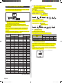
INSTALLATION MANUAL
For authorized service personnel only.
中 文
English
VRF SYSTEM
NETWORK CONVERTOR
UTY-VGGX
Contents
1.
2.
3.
4.
SAFETY PRECAUTIONS ............................................. 2
ACCESSORIES ............................................................ 2
ELECTRICAL REQUIREMENT..................................... 2
SELECTING AN INSTALLATION LOCATION
4.1. Dimensions ............................................................ 3
5. USING THE NETWORK CONVERTOR ....................... 3
■ SETTING METHOD WHEN CONNECTING A GROUP
REMOTE CONTROLLER
6. WIRING
6.1. Wiring method ........................................................ 4
7. INSTALLING THE NETWORK CONVERTOR
7.1. Installation .............................................................. 5
8. CIRCUIT BOARD SETTING ......................................... 5
9. TURNING ON THE POWER......................................... 6
10. ERROR CODE DISPLAY .............................................. 6
■ SETTING METHOD WHEN CONNECTING A SINGLE
SPLIT TYPE INDOOR UNIT
11. WIRING
11.1. Wiring method ...................................................... 7
12. INSTALLING THE NETWORK CONVERTOR
12.1. Installation ............................................................ 8
12.2. Connection of remote controller cable ................. 9
13. CIRCUIT BOARD SETTING ....................................... 10
14. TURNING ON THE POWER....................................... 11
15. ERROR CODE DISPLAY ............................................ 12
PART NO. 9374707089-05
9374707089-05_IM_EN.indd 1
2011-1-20 17:14:41
This mark indicates procedures which,
if improperly performed, might possibly
result in personal harm to the user or
damage to property.
1. SAFETY PRECAUTIONS
• The “SAFETY PRECAUTIONS” indicated in the manual
contain important information pertaining to your safety. Be
sure to observe them.
• Request the user to keep the manual on hand for future
use, such as for relocating or repairing the unit.
WARNING
This mark indicates procedures which, if
improperly performed, might lead to the
death or serious injury of the user.
• Perform electrical work by an authorized service
personnel in accordance with the installation manual
and the electrical wiring regulations or implementation
regulations of the country. Also do not install this unit by
yourself. Improper electric work will cause electric shock
or a fire.
• Perform installation work in accordance with the
installation manual. Request an authorized service
personnel to perform installation work. Do not install this
unit by yourself. Improper installation will cause injury,
electric shock, fire, etc.
• In the event of a malfunction (burning smell, etc.),
immediately stop operation, turn off the electrical breaker,
and consult authorized service personnel.
• Install a leakage circuit breaker to power supply cable
in accordance with the related laws and regulations and
electric company standards.
CAUTION
• Pay abundant care when transporting this unit because it
is a precision device. Improper transportation will cause
trouble.
• Do not touch the switches with sharp objects. Doing so
will cause injury, trouble, or electric shock.
• Do not expose this unit directly to water. Doing so will
cause trouble, electric shock, or heating.
• Do not set vessels containing a liquid on this unit. Doing
so will cause heating, fire, or electric shock.
• Dispose of the packing materials safely. Tear and dispose
of the plastic packing bags so that children cannot play
with them. There is the danger of suffocation if children
play with the original plastic bags.
• Do not insert articles into the slit parts of this unit. Doing
so will cause trouble, heating, or electric shock.
2. ACCESSORIES
The following installation parts are supplied. Use them as
required.
Name and Shape
Q’ty
Installation manual
This manual
• Use a power source exclusively for this unit. Never share
the power source with other electrical equipment. Doing
so will cause fire and electric shock.
Do not install the unit in the following areas:
• Do not install the unit near a source of heat, steam, or
flammable gas.
• Area filled with mineral oil or containing a large amount of
splashed oil or steam, such as a kitchen. It will deteriorate
plastic parts, causing the parts to fall or the unit to leak
water.
• Area that generates substances that adversely affect the
equipment, such as sulfuric gas, chlorine gas, acid, or
alkali. It will cause the copper pipes and brazed joints to
corrode, which can cause refrigerant leakage.
• Area containing equipment that generates
electromagnetic interference. It will cause the control
system to malfunction, preventing the unit from operating
normally.
• Area that can cause combustible gas to leak, contains
suspended carbon fibers or flammable dust, or volatile
inflammables such as paint thinner or gasoline. If gas
leaks and settles around the unit, it can cause a fire.
• Do not use the unit for special purposes, such as storing
food, raising animals, growing plants, or preserving
precision devices or art objects. It can degrade the quality
of the preserved or stored objects.
• Install the unit in a well-ventilated place avoiding rains
and direct sunlight.
• Do not operate this unit when your hands are wet.
Touching the unit with wet hands will cause an electric
shock.
• If children may approach the unit, take preventive
measures so that they cannot reach the unit.
Application
1
Binder
4
Screw (M4 x 20 mm)
4
For mounting the power
supply cable, remote
controller cable and
transmission cable.
For mounting the
network convertor.
3. ELECTRICAL REQUIREMENT
Use
Power
supply
cable
Size
Maximum 1.25 mm
Minimum
0.5 mm2
Transmission cable
0.33 mm
Remote
controller
cable
0.33 mm2
Fuse
capacity
2
Wire type
Remarks
245 IEC 57 or
equivalent
1 ø AC220 - 240 V
50/60Hz, 2 Cable
+ ground (Always
ground the unit)
2
22AWG LEVEL4
(NEMA)
LON WORKS
nonpolar 2 core,
compatible cable
twisted pair solid
core Shielded
22AWG
Polar 3core,
Twisted pair
Use shield cable
3A
* We recommend that you purchase our service parts for
the remote controller cable. Contact service personnel to
purchase this.
En-2
9374707089-05_IM_EN.indd 2
2011-1-20 17:14:50
4. SELECTING AN INSTALLATION LOCATION
SETTING METHOD WHEN CONNECTING A GROUP
REMOTE CONTROLLER
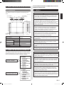
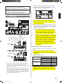
4.1. Dimensions
C
O
R
N
T
L
The network convertor is comprised of a main body and
cover.
WARNING
(Unit : mm)
Ø24 GROMMET
91
89.5
29
Ø15 GROMMET
95 (Hole pitch)
211
95 (Hole pitch)
2 - Ø5
For M4x20mm screws
4 - Ø5
For M4x20mm
screws
241.6
272 (Hole pitch)
288
Power supply
Power consumption (W)
Operating
Temperature (°C)
Packaged
Humidity (%)
Packaged
Dimensions (H × W × D) (mm)
Weight (g)
6. WIRING
67
1ø AC220 - 240V
50/60 Hz
6.5
0 – 46
-10 – 60
0-95 (RH);
No condensation
67× 288 × 211
1500
• Before starting installation work, turn off the power of this
unit and the connection destination. Do not turn on the
power again until installation is completed. Otherwise, it
will cause electric shock or fire.
• Use the accessories or specified power cable and
connection cables. Do not modify power cable and
connection cables other than those specified, do not use
extension cables, and do not use independent branch
wiring. The allowable current will be exceeded and cause
electric shock or fire.
• Install the connection cables securely to the terminal
block. Confirm that external force is not applied to the
cable. Use connection cables made of the specified
cable. If intermediate connection or insertion fixing are
imperfect, it will cause electric shock, fire, etc.
• When connecting the power cable and transmission
cable, layout the wiring so that the cover of this unit is
securely fixed. If the cover is imperfectly fixed, it may
cause fire or overheating of the terminals.
• Perform ground work positively. Do not connect the
ground cable to a telephone ground cable, water pipe, or
conductor rod.
• Always fasten the outside covering of the connection
cable with the cable clamp. (If the insulator is chafed,
electric leakage may occur.)
• When performing cable wiring work, be sure that it does
not touch the user. Doing so will cause injury or electric
shock.
• If any cable is damaged, do not repair or modify it
yourself. Improper work will cause electric shock or fire.
5. USING THE NETWORK CONVERTOR
The network convertor has 2 uses. Since the setting method
is different depending on how the network convertor is used,
refer to the following information to make the settings.
(1) To connect a group
remote controller
(2) To connect a single
split type indoor unit
See items:
6. WIRING
7. INSTALLING THE
NETWORK
CONVERTOR
8. CIRCUIT BOARD
SETTING
9. TURNING ON THE
POWER
10. ERROR CODE
DISPLAY
See items:
11. WIRING
12. INSTALLING THE
NETWORK
CONVERTOR
13. CIRCUIT BOARD
SETTING
14. TURNING ON THE
POWER
15. ERROR CODE
DISPLAY
CAUTION
• Do not bind the remote controller cable and the
transmission cable together with or parallel to the power
supply cable of the indoor and outdoor units. It may cause
erroneous operation.
• When performing wiring work, be careful not to damage
the cable or injure yourself. Also, connect the connectors
securely. Loose connectors will cause trouble, heating,
fire, or electric shock.
• Install the indoor and outdoor units, power cable, signal
cable and remote control cable 1 m away from television
and radio to avoid distorted images and noise.
• Perform wiring so that water does not enter this unit along
the external wiring. Always install a trap to the wiring
or take other countermeasures. Otherwise it will cause
trouble or electric shock or fire.
• Confirm the name of each unit and name of each terminal
block of the unit and connect the wiring in accordance
with the directions given in the manual so that there is no
incorrect wiring. Incorrect wiring will damage the electric
parts and cause smoke and fire.
En-3
9374707089-05_IM_EN.indd 3
2011-1-20 17:14:51
• When installing the connection cables near a source of
electromagnetic waves, use shielded cable.
Otherwise, a breakdown or malfunction could result.
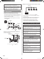
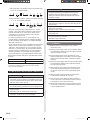
[Example of connecting group remote controllers in series]
Terminal box
• The terminal screws and ground screws have different
shapes. Be sure to install the screws in the correct
locations. If the screws are installed in the wrong
locations, the circuit board could be damaged.
6.1. Wiring method
Number of connected network convertors
• Up to a total of 16 network convertors (UTY-VGGX) and
touch panel controllers can be connected in the VRF system.
K
RC UNIT
K K
UNIT
L1 + L2 + L3 + L4 + L5 + L6 + L7
100m
• Up to 4 group remote controllers can be connected to1
network convertor (UTY-VGGX).
• Use of a terminal box is recommended when a junction is
made in the wiring.
• Total remote controller cable length when connected to 1
converter 100m
• Do not bind the power cable, remote controller cable and
transmission cable to avoid an erroneous operation.
• Use ground cable to ground the network convertor.
• Use shield cable for transmission cable and remote
controller cable. The shield metal should be grounded.
Transmission
cable
Outdoor
unit
Remote controller
cable
Network
convertor
WARNING
Indoor
unit
• Always use the accessories and specified installation
work parts. Check the state of the installation parts. Not
using the specified parts will cause units to fall off, water
leakage, electric shock, fire, etc.
Wired remote
controller
Wireless remote
controller
Group remote
controller
[Example of connecting group remote controllers in a
parallel arrangement]
Transmission Cable
to VRF System
7. INSTALLING THE NETWORK CONVERTOR
Transmission Cable
to VRF System
• Install at a place that can withstand the weight of the unit
and install positively so that the unit will not topple or fall.
• When installing this unit, make sure that there are no
children nearby.
Otherwise, injury or electric shock could result.
• Install a circuit breaker.
Otherwise, electric shock or fire could result.
CAUTION
FUSE (3 A)
1Ø 50 Hz
220-240 V SWITCH
K
POWER
SUPPLY
RC UNIT
K K
UNIT
Power Supply
NETWORK CONVERTOR
L1 + L2 + L3 + L4 + L5 + L6
or
100m
• Do not set the DIP switch or rotary switch of this unit
except as specified in this installation manual or the
instruction manual supplied with the air conditioner.
Setting the switches other than specified will cause an
accident or trouble.
• Use an insulated screwdriver to set the DIP switches.
• Before opening the case of this unit, completely discharge
static electricity charged on your body. Not doing so will
cause trouble.
• Do not touch the circuit board and circuit board parts
directly with your hands.
Otherwise, injury or electric shock could result.
• Tightening the mounting screws too tight will damage the
case of this unit.
• Be careful so that the front cover does not fall after the
front cover screws are removed.
Otherwise, injury could result.
En-4
9374707089-05_IM_EN.indd 4
2011-1-20 17:14:52
7.1. Installation
(1) Remove the four screws (M4 x 6 mm), and then remove
the cover.
•.d
e
n
u
org8.
CIRCUIT BOARD SETTING
Set network convertor rotary switch SW110, SW111 and Dip
switch SW103, SW107, SW108, SW109.
(2) Pass the power supply cable, remote controller cables and
transmission cables through the bushing and pull it into
the network convertor.
(3) Form the binder (push mount) provided into a ring shape
and pass each of the cables - the power supply cable,
remote controller cables, transmission cables - through it.
(4) Route the power supply cable, remote controller cables
and transmission cables to their respective terminal block
and ground properly.
(5) After the wiring of the cables, press the binder (push
mount) that had been shaped into a ring and insert it in the
hole in the box for securing the binder (push mount).
(6) Securely tighten the binder (push mount) and then confirm
that the cable will not come out.
(7) Once the wiring of the cables has been completed, mount
of the cover to the network convertor. Use the screws
(M4 x 6 mm) to mount the cover.
(8) Use the four screws (M4 x 20 mm) provided to mount the
network convertor to the behind ceiling, wall, floor or other
suitable location.
[Rotary switch-SW110, SW111] Convertor address
settings
Set the convertor address in accordance with the following
table for each network convertor.
* Be sure to set the convertor address different from the touch
panel controller address (refer to the setting manual for the
touch panel controller).
* Each convertor address can be selected freely but the same
address cannot be used more than once.
* Example: When SW110 is set to “1” and SW111 is set to “4”,
the convertor address will be “14”.
Convertor address
0
SW110 ★0
Rotary switch
SW111 ★0
1
0
1
2
0
2
Convertor address
SW110
Rotary switch
SW111
9
0
9
10 11 12 13 14 15
1 1 1 1 1
1
0 1 2 3 4
5
8
0
8
3
0
3
4
0
4
5
0
5
6
0
6
7
0
7
(★: Factory setting)
[DIP switch - SW103] Group remote controller
convertor setting
Set the switches as follows.
DIP switch - SW103
1
2
3
4
5
6
7
8
Fixed Fixed Fixed Fixed Fixed Fixed Fixed Fixed
at ON at ON at ON at ON at OFF at OFF at OFF at OFF
[DIP switch - SW107, SW108, SW109]
Set the switches as follows.
Tightening torque for installing cables to terminal block
DIP switch-SW107 DIP switch-SW108 DIP switch-SW109
1
2
1
2
1
2
Fixed at Fixed at Fixed at Fixed at Fixed at Fixed at
OFF
OFF
OFF
OFF
OFF
OFF
0.8 to 1.2 N • m (8 to 12 kgf • cm)
En-5
9374707089-05_IM_EN.indd 5
2011-1-20 17:14:52
9. TURNING ON THE POWER
CAUTION
• Before turning on the power, check that the voltage is
within the rated range. If operated outside the rated
range, erroneous operation cannot be prevented and
cannot be compensated.
(1) Check the network convertor wiring and switch settings on
the circuit board.
(2) Check the wiring and switch settings for the VRF system.
For the wiring and switch settings method, refer to the
installation instruction sheet of each unit.
(3) Turn on the power for the VRF system.
(4) Turn on the power for the network convertor.
• The network convertor is initialized for a period of
approximately ten seconds after turned on the power.
is displayed on D129 during this period.
• After initial setting completely the operation mode will
be started.
is displayed on D129.
* Network convertor does not operate during initialization.
Do not attempt control from the units.
* An error code will appear on D129 in the event of a
malfunction.
10. ERROR CODE DISPLAY
Error code
Contents
No error (operation mode)
SETTING METHOD WHEN CONNECTING A SINGLE
SPLIT TYPE INDOOR UNIT
11. WIRING
WARNING
• Before starting installation work, turn off the power of this
unit and the connection destination. Do not turn on the
power again until installation is completed. Otherwise, it
will cause electric shock or fire.
• Use the accessories or specified power cable and
connection cables. Do not modify power cable and
connection cables other than those specified, do not use
extension cables, and do not use independent branch
wiring. The allowable current will be exceeded and cause
electric shock or fire.
• Install the connection cables securely to the terminal
block. Confirm that external force is not applied to the
cable. Use connection cables made of the specified
cable. If intermediate connection or insertion fixing are
imperfect, it will cause electric shock, fire, etc.
• When connecting the power cable and transmission
cable, layout the wiring so that the cover of this unit is
securely fixed. If the cover is imperfectly fixed, it may
cause fire or overheating of the terminals.
• Perform ground work positively. Do not connect the
ground cable to a telephone ground cable, water pipe, or
conductor rod.
• Always fasten the outside covering of the connection
cable with the cable clamp. (If the insulator is chafed,
electric leakage may occur.)
• When performing cable wiring work, be sure that it does
not touch the user. Doing so will cause injury or electric
shock.
• If any cable is damaged, do not repair or modify it
yourself. Improper work will cause electric shock or fire.
Initial setting
Main PCB error
Remote controller communication error
Network communication error
EEPROM error
Address setting error
CAUTION
• Do not bind the remote controller cable and the
transmission cable together with or parallel to the power
supply cable of the indoor and outdoor units. It may cause
erroneous operation.
• When performing wiring work, be careful not to damage
the cable or injure yourself. Also, connect the connectors
securely. Loose connectors will cause trouble, heating,
fire, or electric shock.
• Install the indoor and outdoor units, power cable, signal
cable and remote control cable 1 m away from television
and radio to avoid distorted images and noise.
• Perform wiring so that water does not enter this unit along
the external wiring. Always install a trap to the wiring
or take other countermeasures. Otherwise it will cause
trouble or electric shock or fire.
• Confirm the name of each unit and name of each terminal
block of the unit and connect the wiring in accordance
with the directions given in the manual so that there is no
incorrect wiring. Incorrect wiring will damage the electric
parts and cause smoke and fire.
En-6
9374707089-05_IM_EN.indd 6
2011-1-20 17:14:53
• When installing the connection cables near a source of
electromagnetic waves, use shielded cable.
Otherwise, a breakdown or malfunction could result.
*3 Connect a single big multi system to a single network
convertor. Do not connect 2 big multi systems, or a big
multi system and a single model system.
• The terminal screws and ground screws have different
shapes. Be sure to install the screws in the correct
locations. If the screws are installed in the wrong
locations, the circuit board could be damaged.
11.1. Wiring method
Big Multi
Single
Split
*4 Network convertor is necessary for each indoor unit.
*5 For using J series heat pump system, “AUTO” and “FAN”
mode should not be used.
*6 When connecting the J-series heat pump model, the set
operation conditions will be displayed on the control unit.
Therefore, the indoor unit may enter the operation standby
condition as described below.
Ex. 1) If FAN setting is selected from the control unit, the
LED on the indoor unit will flash and the unit will
enter the operation standby condition. Select another
operation mode to clear the standby condition.
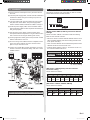
[Example of connecting single split type
indoor unit in a parallel arrangement]
Case 1
1Ø 50 Hz
220-240 V
Indoor unit
Transmission Cable
Transmission Cable
FUSE (3 A)
SWITCH
Max. 16 units
K
POWER
SUPPLY
RC UNIT
K K
UNIT
Power Supply
Wired remote controller
Transmission Cable
Transmission Cable
1Ø 50 Hz
220-240 V
Indoor unit
Max. 2 units
FUSE (3 A)
Number of connected network convertors
• Up to 100 network convertors may be connected in the VRF
system.
NETWORK CONVERTOR
Case 2
Ex. 2) If an operation mode that is different from a currently
operating indoor unit is selected from the control unit,
the LED on the indoor unit will flash and the unit will
enter the operation standby condition. Select the
operation mode of the other indoor unit to clear the
standby condition. In addition, if operation becomes
possible, such as by stopping the other indoor
unit, the standby condition will be cleared and the
indoor unit will automatically start operating with the
selected mode.
Max. 16 units
* A single network convertor is considered as a single
refrigerant system, irrespective of the number of connected
single models.
Compatible indoor units
J-series
SWITCH
K
POWER
SUPPLY
RC UNIT
K K
UNIT
Big multi
Power Supply
NETWORK CONVERTOR
*1 Up to 16 indoor units may be controlled with a single
network convertor, however multiple indoor units
connected to the network convertor are generally required
to have the same setting.
*2 Always use indoor units with the same RC model or the
same system type when connecting multiple indoor units.
Refer to “[DIP switch - SW103 <1, 2, 3, 4>] RC model or
system type setting” in “13 CIRCUIT BOARD SETTING”
for information about RC models.
Wireless RC model
Simultaneous model
Individual model
Single split type
Wired RC model
Wireless RC model
Window type
{
¯
{
{
{
{
¯
¯
* The following indoor unit models may be controlled from
a network convertor. However, the indoor unit cannot be
controlled if a wired remote controller cannot be connected
to it.
En-7
9374707089-05_IM_EN.indd 7
2011-1-20 17:14:53
1) When 4th letter is an alphabet, indoor unit models using
the “N” or “U” SERIES NAME.
2) When 4th letter is a figure, indoor units models using the
“L”, “U” or “F” CONTROL METHOD.
* When connecting an indoor unit that has an “L” control
method, connect the remote controller for VRF (UTB-*U*,
UTB-*R* and UTB-*P*) to control from a wired remote
controller. Do not connect the wired remote controller
included with the indoor unit.
* For indoor units that have an “L” control method, only
included remote controllers with RC numbers indicated in
the RC number/RC model table in “13 CIRCUIT BOARD
SETTING” can be used.
* As the network convertor is not compatible with “Flow direction
setting” (except for wired remote controllers), “Anti-freeze”,
“Filter sign”, “Set temperature 10-15°C” (except for models
using the “U” control method), ‘Room temperature detection
location’ (except for models using the “U” control method),
‘Model name display’, and ‘Electricity charge calculation’,
control and display are not possible with the controller units.
Wired remote controller that can be connected with network
convertor
*
Model name
UTB- UB
RC Number
AR-3TA
**
( arbitrary character)
*
* RC Number is displayed on the back of the remote controller.
* Only this model is available.
12. INSTALLING THE NETWORK CONVERTOR
WARNING
• Always use the accessories and specified installation
work parts. Check the state of the installation parts. Not
using the specified parts will cause units to fall off, water
leakage, electric shock, fire, etc.
• Install at a place that can withstand the weight of the unit
and install positively so that the unit will not topple or fall.
CAUTION
• Do not set the DIP switch or rotary switch of this unit
except as specified in this installation manual or the
instruction manual supplied with the air conditioner.
Setting the switches other than specified will cause an
accident or trouble.
• Use an insulated screwdriver to set the DIP switches.
• Before opening the case of this unit, completely discharge
static electricity charged on your body. Not doing so will
cause trouble.
• Do not touch the circuit board and circuit board parts
directly with your hands.
Otherwise, injury or electric shock could result.
• Tightening the mounting screws too tight will damage the
case of this unit.
• Be careful so that the front cover does not fall after the
front cover screws are removed.
Otherwise, injury could result.
12.1. Installation
(1) Remove the four screws (M4 x 6 mm), and then
remove the cover.
(2) Pass the power supply cable, remote controller cables
and transmission cables through the bushing and pull
it into the network convertor.
(3) Form the binder (push mount) provided into a ring
shape and pass each of the cables - the power supply
cable, remote controller cables, transmission cables through it.
(4) Route the power supply cable, remote controller cables
and transmission cables to their respective terminal
block and ground properly.
(5) After the wiring of the cables, press the binder (push
mount) that had been shaped into a ring and insert
it in the hole in the box for securing the binder (push
mount).
(6) Securely tighten the binder (push mount) and then
confirm that the cable will not come out.
(7) Once the wiring of the cables has been completed,
mount of the cover to the network convertor. Use the
screws (M4 x 6 mm) to mount the cover.
(8) Use the four screws (M4 x 20 mm) provided to mount
the network convertor to the behind ceiling, wall, floor
or other suitable location.
• When installing this unit, make sure that there are no
children nearby.
Otherwise, injury or electric shock could result.
• Install a circuit breaker.
Otherwise, electric shock or fire could result.
En-8
9374707089-05_IM_EN.indd 8
2011-1-20 17:14:54
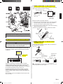
(1) WHEN CONNECTING TO THE CONNECTOR
Connect the remote controller cable (cord) to the connecting
cable (cord), and insert it to the connector.
Connecting cable (cord)
Connector
Indoor unit
PCB
Remote controller
cable (cord)
Terminal block to
outdoor unit /
power supply
Modify the cable as per below methods.
1 Use a tool to cut off the terminal on the end of the remote
controller cable (cord), and then remove the insulation
from the cut end of the cable as shown in Fig. 1.
2 Connect the remote controller cable (cord) and connecting
cable (cord) as shown in Fig. 2.
3 Be sure to insulate the connection between the cables.
Fig. 1
Tightening torque for installing cables to terminal block
0.8 to 1.2 N • m (8 to 12 kgf • cm)
Fig. 2
White
Remote
Red
controller cable
White
Red
Connector
Black
Insulated
connection
Black
12.2. Connection of remote controller cable
Connecting
cable (cord)
(2) WHEN CONNECTING TO THE EXCLUSIVE
TERMINAL BLOCK
CAUTION
• When connecting the remote controller cable (cord) to
the indoor unit, do not connect it to the outdoor unit or the
power terminal block. It may cause a failure.
Connect the end of remote controller cable (cord) directly to
the exclusive terminal block.
M4 screw
When connecting Indoor unit and Network convertor with
the Remote controller cable, the following items should be
considered.
Indoor unit
remote controller
cable(cord)
Terminal block
Terminal block to
remote controller
Remote controller cable (cord)
K
POWER
SUPPLY
RC UNIT
Terminal block to
outdoor unit /
power supply
Indoor unit
PCB
K K
UNIT
NETWORK CONVERTOR
There are 2 methods to connect the remote controller
cable (cord) to the indoor unit. One is the connection using
contained connecting cable (cord), and the other is the
connection the remote controller cable (cord) is connected to
the exclusive terminal block of the indoor unit.
Exclusive terminal block for remote controller connection
method is different depending on each model. Modify the
remote controller cable (cord) as per below description and
connect it.
(For the details, refer to the installation manual of the indoor
unit to be used.)
It may be failed if it is connected to the outdoor unit or the
terminal block for power supply.
En-9
9374707089-05_IM_EN.indd 9
2011-1-20 17:14:54
(2) [DIP switch-SW103 <1, 2, 3, 4>] Signal
conversion type setting
13. CIRCUIT BOARD SETTING
Set network convertor rotary switch SW110, SW111 and Dip
switch SW103, SW107, SW108, SW109.
Use the pattern A or pattern B setting method according to the
model name.
(2) - 1. Selecting the pattern
1) When 4th letter is an alphabet,
Pattern A
SERIES NAME “N” or “U”
Indoor unit model (1)
2) When 4th letter is a figure,
Control method “F” or “U”
(1) [Rotary switch-SW110, SW111] set the
refrigerant circuit address
Control method “L”
A single network convertor is considered as a single
refrigerant system, irrespective of the number of connected
single models.
In the case of multiple refrigerant system, set SW110 and
SW111 as shown in the following table for each Network
convertor.
Example: When SW110 is set to “3” and SW111 is set to “0”,
the refrigerant circuit address will be “30”.
Rotary
Switch Setting
Refrigerant
circuit
address
SW110
SW111
0
1
2
3
4
5
6
7
8
9
10
11
12
13
14
15
16
17
18
19
20
21
22
23
24
25
26
27
28
29
30
★0
0
0
0
0
0
0
0
0
0
1
1
1
1
1
1
1
1
1
1
2
2
2
2
2
2
2
2
2
2
3
★0
1
2
3
4
5
6
7
8
9
0
1
2
3
4
5
6
7
8
9
0
1
2
3
4
5
6
7
8
9
0
Rotary
Switch Setting
Refrigerant
circuit
address
SW110
SW111
31
32
33
34
35
36
37
38
39
40
41
42
43
44
45
46
47
48
49
50
51
52
53
54
55
56
57
3
3
3
3
3
3
3
3
3
4
4
4
4
4
4
4
4
4
4
5
5
5
5
5
5
5
5
1
2
3
4
5
6
7
8
9
0
1
2
3
4
5
6
7
8
9
0
1
2
3
4
5
6
7
98
99
9
9
8
9
Pattern A
Pattern B
Indoor unit model (2)
(2) - 2. Setting methods
(1) Setting method for Pattern A
Set the system type in accordance with the table.
Outdoor unit System
type
Heat pump model
Cooling only model
Factory setting
1
OFF
ON
ON
DIP switch-SW103
2
3
4
ON
OFF
OFF
ON
OFF
ON
ON
ON
ON
(2) Setting method for Pattern B
Set the remote controller model compatible with the number
on the back of the wired remote controller packaged with the
single model or big multi model as shown in the following
table.
The following remote controller cannot be connected with the
network convertor. (See En-9)
RC Number
Rear View
(★: Factory setting)
En-10
9374707089-05_IM_EN.indd 10
2011-1-20 17:14:55
DIP switch-SW103
1
2
3
4
RC number
(4) [DIP switch-SW107<1,2>,DIP switch-SW108<1,2>,
DIP switch-SW109<1,2>] Function setting
Set functions as shown in the following table.
EZ-099DHSE-R,
EZ-000DHSE-R,
EZ-0001HSE-R,
EZ-000GHSE-R,
EZ-00004HSE-R,
EZ-00005HSE-R,
EZ-0015HSE-R,
EZ-0019HSE-R,
EZ-099DHSEFR,
EZ-0001HSEFR,
EZ-000DHSEFR,
EZ-000GHSEFR,
EZ-0015HSEFR
EZ-0994HSE-R,
EZ-000EHSE-R,
EZ-0994HSEFR
EZ-099CWSE-R,
EZ-000AWSE-R,
EZ-0001WSE-R,
EZ-000FWSE-R,
EZ-0012WSE-R,
EZ-099CWSEFR,
EZ-0001WSEFR,
EZ-000AWSEFR
EZ-09906WSE-R,
EZ-000BWSE-R,
EZ-09906WSEFR
NO.
OFF OFF OFF OFF
Detail
OFF
ON
★Invalidity Validity Auto changeover
validity / invalidity
setting
Set to OFF when
connecting the
J-series heat pump
model
1
DIP switchSW109
OFF OFF OFF ON
2
ON OFF OFF OFF
DIP switchSW107
DIP switchSW108
1
2
1
2
ON OFF OFF ON
* Set to OFF when a
remote sensor is not
used (duct model).
★Invalidity Validity Auto restart validity /
invalidity setting
Not used
–
★Fixed at
OFF
★Invalidity Validity Wired RC validity /
invalidity setting
★Fixed at
–
Not used
OFF
★Fixed at
–
Not used
OFF
(★: Factory setting)
14. TURNING ON THE POWER
(3) [DIP switch-SW103 <5, 6, 7, 8>] Setting the
number of connected indoor units
Set the number of connected indoor units as shown in the
following table.
Number
of the
connected
indoor unit
1
2
3
4
5
6
7
8
9
10
11
12
13
14
15
16
Switch state
DIP switch-SW103
5
6
7
8
★OFF
OFF
OFF
OFF
OFF
OFF
OFF
OFF
ON
ON
ON
ON
ON
ON
ON
ON
★OFF
OFF
OFF
OFF
ON
ON
ON
ON
OFF
OFF
OFF
OFF
ON
ON
ON
ON
★OFF
OFF
ON
ON
OFF
OFF
ON
ON
OFF
OFF
ON
ON
OFF
OFF
ON
ON
★OFF
ON
OFF
ON
OFF
ON
OFF
ON
OFF
ON
OFF
ON
OFF
ON
OFF
ON
(★: Factory setting)
CAUTION
• Before turning on the power, check that the voltage is
within the rated range. If operated outside the rated
range, erroneous operation cannot be prevented and
cannot be compensated.
(1) Check the network convertor wiring and switch settings on
the circuit board.
(2) Check the wiring and switch settings for the VRF system
and big multi system or single model. For the wiring and
switch settings method, refer to the installation instruction
sheet of each unit.
(3) Turn on the power for the VRF system and big multi
system or single model.
(4) Turn on the power for the network convertor.
• The network convertor is initialized for a period of
approximately ten seconds after turned on the power.
is displayed on D129 during this period.
• After initial setting completely the operation mode will
be started.
is displayed on D129.
* Network convertor does not operate during initialization.
Do not attempt control from the units.
* An error code will appear on D129 in the event of a
malfunction.
En-11
9374707089-05_IM_EN.indd 11
2011-1-20 17:14:55
15. ERROR CODE DISPLAY
Error code
Contents
No error (operation mode)
Initial setting
Main PCB error
Remote controller communication error
Peripheral device communication error
EEPROM error
Address setting error
Indoor unit error
When error occurs in the remote controller connected to the
network converter, please refer to the installation manual of
the remote controller and indoor unit.
*
LON WORKS
is registered trademark of Echelon Corporation in the United States and other countries.
En-12
9374707089-05_IM_EN.indd 12
2011-1-20 17:14:55