1
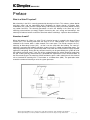
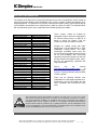
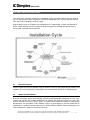
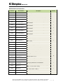
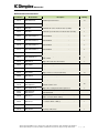
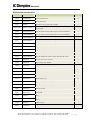
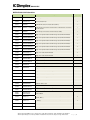
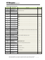
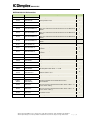
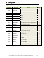
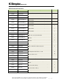
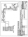
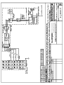
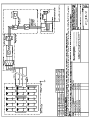
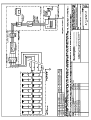
SOLAR PV
INSTALLATION MANUAL
FOR
DIMPLEX SOLAR PHOTOVOLTAIC KITS
Please read this manual carefully before installing the system
and carry out the installation procedures as per the instructions.
DXPVP052 Issue: 2
GDC Group Limited, Millbrook House, Grange Drive, Hedge End, Southampton, Hants, SO302DF, United Kingdom.
GDC Group Ltd all rights reserved. Specifications included in this document are subject to change without notice.
P a g e |1
SOLAR PV
TABLE OF CONTENTS
SECTION 1
Introduction
4
SECTION 2
Installation Cycle
5
2.1 Check kit contents
2.2 Read instruction manual
5
5
SECTION 3
Risk Assessment / Planning Permission
6
SECTION 4
Install D.C. components
6
SECTION 5
Install PV Roof Mounting Kit
8
5.1 PV Layout Installations
5.2 PV Array Layouts
5.3 Preparing the Roof for Installation
5.4 Fastening the Roof Hooks
5.5 Install Mounting Rails
5.6 Install Flexible and Fixed Connectors
5.7 Install Sliding Slot Nuts
5.8 Install the Middle, Corner Clamps and Modules
5.9 Mounting in A Cross Bracing Pattern
5.10 Install Dimplex End Caps
5.11 Connect Earth and D.C Cables for PV Array
12
12
13
13
14
14
14
15
15
15
16
Interface PV System To Electricity Company
17
6.1 Install the Generation Meter
6.2 Works required by site electrician
17
18
SECTION 7
Testing Solar PV Installation
19
SECTION 8
Commissioning, Operating and Maintenance
19
8.1 Maintenance
19
Shut Down/ Start Up Procedure
19
9.1 System Start Up
9.2 System Shut Down
19
19
SECTION 6
SECTION 9
SECTION 10
Appendices
Kit Component Lists
Wiring Schematics for the different Dimplex Kits
CAD drawings for the different PV roof mounting systems
20
34
51
GDC Group Limited, Millbrook House, Grange Drive, Hedge End, Southampton, Hants, SO302DF, United Kingdom.
GDC Group Ltd all rights reserved. Specifications included in this document are subject to change without notice.
P a g e |2
SOLAR PV
Preface
What is a Solar PV system?
Most electricity in the UK is currently generated by burning fossil fuels. This releases carbon dioxide
and other gases into the atmosphere which contributes to climate change. A Dimplex Solar
Photovoltaic (PV) system converts sunlight directly into electricity cleanly and silently without creating
any carbon emissions. The electricity generated is used in the building in the same way as the
electricity purchased from an energy supplier. Harnessing the sun’s energy and converting it into
electricity will reduces fuel bills and at the same time reduces a building’s impact on the environment.
How does it work?
When light protons hit silicon in a solar PV cell, electrical energy is created in the form of Direct
Current (D.C.) This electricity flows from the array via a D.C. cable through a D.C. isolator and is
collected at the inverter which is often located in the roof space. The inverter converts the D.C.
electricity to Alternating Current (A.C.) so that it can be used within the building. The now A.C.
electricity is passed to the building’s electricity system via an A.C. isolator and generation meter. The
electricity generated by the PV system works hand in hand with the existing electrical supply to power
appliances and lighting. During the day sufficient electricity can be generated by the system for all of
the building’s electrical needs. If not, this will be supplemented by the normal electricity supply from
the grid. If during the day more electricity is generated than required this excess will be fed back to
the main electricity grid. The electricity purchased from the grid is sold in electrical units. An electrical
unit as itemised on electricity bills is also known as a kilowatt hour (kWh). The generation meter
records the amount of electricity or units the system generates.
GDC Group Limited, Millbrook House, Grange Drive, Hedge End, Southampton, Hants, SO302DF, United Kingdom.
GDC Group Ltd all rights reserved. Specifications included in this document are subject to change without notice.
P a g e |3
SOLAR PV
SECTION 1: INTRODUCTION
The purpose of this document is to provide information for the owner and guidelines for the installer to
help ensure that the Dimplex Solar Photovoltaic (PV) system is properly installed and operates to its
designed potential. This document sets out key criteria that describe a quality system and key design
and installation considerations that should be met in order to achieve this goal. This document deals
with roof mounted systems and is applicable for the following Dimplex kit models:
SMA Plain Tile
DXPV138/230/2/3PT
DXPV184/230/2/4PT
DXPV207/230/3/3PT
DXPV230/230/2/5PT
DXPV276/230/2/6PT
DXPV276/230/3/4PT
DXPV276/230/4/3PT
DXPV345/230/3/5PT
DXPV368/230/2/8PT
DXPV368/230/4/4PT
DXPV414/230/3/6PT
DXPV460/230/2/10PT
DXPV460/230/4/5PT
DXPV552/230/4/6PT
POWERONE Plain Tile
DXPV138/230/2/3(P)PT
DXPV184/230/2/4(P)PT
DXPV207/230/3/3(P)PT
DXPV230/230/2/5(P)PT
DXPV276/230/2/6(P)PT
DXPV276/230/3/4(P)PT
DXPV276/230/4/3(P)PT
DXPV345/230/3/5(P)PT
DXPV368/230/2/8(P)PT
DXPV368/230/4/4(P)PT
DXPV414/230/3/6(P)PT
DXPV460/230/2/10(P)PT
DXPV460/230/4/5(P)PT
DXPV552/230/4/6(P)PT
SMA Slate
DXPV138/230/2/3S
DXPV184/230/2/4S
DXPV207/230/3/3S
DXPV230/230/2/5S
DXPV276/230/2/6S
DXPV276/230/3/4S
DXPV276/230/4/3S
DXPV345/230/3/5S
DXPV368/230/2/8S
DXPV368/230/4/4S
DXPV414/230/3/6S
DXPV460/230/2/10S
DXPV460/230/4/5S
DXPV552/230/4/6S
POWERONE Slate
DXPV138/230/2/3(P)S
DXPV184/230/2/4(P)S
DXPV207/230/3/3(P)S
DXPV230/230/2/5(P)S
DXPV276/230/2/6(P)S
DXPV276/230/3/4(P)S
DXPV276/230/4/3(P)S
DXPV345/230/3/5(P)S
DXPV368/230/2/8(P)S
DXPV368/230/4/4(P)S
DXPV414/230/3/6(P)S
DXPV460/230/2/10(P)S
DXPV460/230/4/5(P)S
DXPV552/230/4/6(P)S
These systems should be installed by
competent installers who have completed a
PV installer training course. In order for th
owner to collect the Feed-in Tariff the
installer also needs to be MCS accredite.
Dimplex has worked closely with Logic
Certification in the development of a Solar
Photovoltaic training course. This Logic
Certification accredited course forms the
basis of Dimplex Accredited Installer training
for PV and candidates who successfully
complete training with Dimplex will not only
achieve Dimplex Accredited Installer status,
but also be automatically registered with
Logic Certification.
Please
visit
our
website
http://www.dimplexrenewables.co.uk/
to
learn more about Dimplex Solar Photovoltaic
Systems Training and how to become MCS
installer certified.
Thank you for choosing Dimplex solar
photovoltaic kits. With proper operation and
maintenance, our kits will provide you with
clean, renewable solar electricity for many
years.
This manual does not list all precautions needed for safe work. Any PV system must comply
with Health and Safety Requirements and other relevant standards and Codes of Practice.
This manual provides guidelines for installation, but it does not guarantee the quality of
installation work. Please complete all work in a responsible and professional manner.
Electrical work should be performed by a qualified electrician. For full information on PV
design and installation, refer to the Photovoltaic’s in Buildings Guide to the installation of PV
systems 2nd Edition (DTI/Pub URN 06/1972) and BS 7671.
GDC Group Limited, Millbrook House, Grange Drive, Hedge End, Southampton, Hants, SO302DF, United Kingdom.
GDC Group Ltd all rights reserved. Specifications included in this document are subject to change without notice.
P a g e |4
SOLAR PV
SECTION 2. INSTALLATION CYCLE
The scope of this document includes the installation of the PV array to the roof and the connection of
the D.C. wiring to the inverter and provides information regarding the A.C. wiring required to connect
the inverter into the building’s electricity supply.
A typical project cycle for a Dimplex solar photovoltaic kit is shown below. It shows consideration of
the PV system from the start of the project, through the stages of installation and commissioning
finishing with operation and maintenance.
2.1
Check Kit Contents
Check kit contents prior to installation. Every kit contains a part list with component descriptions and
quantities. Ensure all components and quantities are present before starting the installation project.
2.2
Read Instruction Manual
All of the instructions should be thoroughly read and understood before attempting to install, wire,
operate and maintain the Dimplex photovoltaic kits. Contact with electrically active parts of the kits
such as terminals can result in burns, sparks, and lethal shock whether the module is connected or
disconnected. The installation of solar modules requires a great degree of skill and should only be
performed by a qualified licensed professional, including, without limitation, licensed contractors and
licensed electricians. Keep this manual for reference.
GDC Group Limited, Millbrook House, Grange Drive, Hedge End, Southampton, Hants, SO302DF, United Kingdom.
GDC Group Ltd all rights reserved. Specifications included in this document are subject to change without notice.
P a g e |5
SOLAR PV
SECTION 3. RISK ASSESSMENT/PLANNING PERMISSION
Dimplex solar PV packages bring together high efficiency PV modules with an inverter, roof mounting
system, generation meter and associated cables and isolators to create a solution for residential and
light commercial properties. Designed for both retro fit and new build projects, the systems protrude
less than 200mm above the roof and so are classed as permitted development in both England,
Scotland and Wales do not require planning permission in non-conservation areas. Despite the recent
changes to legislation we recommend in all cases that you check with your local planning authority
before you commit to installing our solar PV kits. This document does not address health and safety
matters, a risk assessment and works method statement should be completed prior to commencing
the installation.
SECTION 4. INSTALL D.C. COMPONENTS
•
Step 1: Identify a suitable location for the inverter (DXPVI0000) or DXPVI0000(P))
preferably in the loft or attic space.
•
•
•
•
•
•
•
•
Make sure the location is not easily accessible by children
and
in an area free from explosive or corrosive
atmospheres.
For residential installations the inverter is typically located
in the attic or loft space.
The inverter must be mounted vertically on a wall or pole.
Do not mount horizontally as adequate heat dissipation
cannot be ensured.
Make sure the Inverter is mounted in a location where the
ambient temperature range is –25 to +65 °C. The Inverter
may derate power output and shut down if it gets too hot.
Also at extremely cold temperatures, the front panel LCD
may not function normally.
A space of at least 300mm to 500mm around the
enclosure guarantees optimum ventilation, if necessary
use forced fan ventilation.
Unless walls are properly insulated, avoid mounting the
inverter on any wall that is directly exposed to the sun or a
heat source such as back boiler wall.
Only work on the inverter when it is fully disconnected and
observe the heat sink temperature. Work should only be carried out by qualified
personnel.
To minimize resistance and resulting power loss, make sure the wire lengths between the PV
array and the inverter and between the inverter and the main utility service panel are kept to a
minimum.
A 10 meter D.C. cable is included in the kit contents to connect the solar PV array on the roof
to the inverter and is routed through the over lap in the roof membrane into the attic space.
Ensure the inverter is mounted directly below this cable entry to ensure successful connection
to the inverter.
If the inverter has an integrated D.C. isolator ensure it is in the off position.
GDC Group Limited, Millbrook House, Grange Drive, Hedge End, Southampton, Hants, SO302DF, United Kingdom.
GDC Group Ltd all rights reserved. Specifications included in this document are subject to change without notice.
P a g e |6
SOLAR PV
Refer to the installation manual of the inverter manufacturer for further installation procedures
and guidelines.
•
•
Step 2: Identify a suitable location for the D.C. isolator (DXPVDC1, 2 or 3), preferably
located adjacent to the inverter (DXPVI0000) or (DXPVI0000(P)).
•
The D.C. isolator provides a means of manually
electrically isolating the entire PV array. Such
electrical isolation is required during system
installation and any subsequent system maintenance
or repair work.
•
The isolator should be located adjacent to, or
integrated in the inverter.
•
Ensure the isolator is in the off position before any
work is carried out.
•
An additional D.C. isolator may be specified for systems with long D.C. cable runs
(typically at the point of cable entry into the building) – so as to provide a means of
isolating the cable for safety reasons or maintenance works.
•
The D.C. isolator(s) must be affixed with the label ‘PV array D.C.isolator’ which is
contained in the kit contents (DXPVWLPK1).
Step3: Route the supplied D.C. 10 meter cable’s DXPVC10/1 and DXPVC10/2 through
the overlap in the roof membrane from the attic space.
•
This D.C. cable should be positioned and secured to
the rafters and labelled D.C. power do not
disconnect under load.
•
The cables used for wiring the D.C. section of a gridconnected PV system need to withstand the
environmental, voltage and current conditions at
which they may be expected to operate. This
includes heating effects of both current and solar
gain.
•
Should the installer require additional cable please
contact Dimplex for specifications. If the D.C. 10
meter cable’s included in the kit contents is not used then the maximum distances will
depend on the wire gauges used and PV array output voltages.
To comply with the current version of BS 7671.The installer must secure coloured cable
sleeves to the cables as follows:
Positive cable – Brown sleeve
Negative cable – Grey sleeve
GDC Group Limited, Millbrook House, Grange Drive, Hedge End, Southampton, Hants, SO302DF, United Kingdom.
GDC Group Ltd all rights reserved. Specifications included in this document are subject to change without notice.
P a g e |7
11
7
8
5
10
1
4
13
3
EXAMPLE OF A 1x3 SOLAR SYSTEM FOR SLATE ROOFS
9
DXPVRKRHST1
DXPVRKSB100
DXPVRKSBM81
DXPVRKXC1
10
11
12
13
2
10
20
8
10
RK SLATE BRACKET
SEATING BOLT 100mm
SLIDE NUT M8
CROSS CONNECTOR
4
RAIL 3.2m
CENTER CLAMP BKT
DRAWN BY
DATE
SCALE
ISSUE
PROJECT
1
---
A3
SOLAR PV
30-SEPT-10
G.MURRAY
DRG NO
SLATE 1 X 3 SYSTEM
TITLE
THIS DRAWING IS SUPPLIED IN CONFIDENCE AND THE COPYRIGHT THEREOF IS THE
PROPERTY OF GLEN DIMPLEX : IT MUST NOT BE USED BY A THIRD PARTY WITHOUT
PRIOR PERMISSION.
C 2010
DXPVRKMC1
DXPVRKMR3
8
9
10
M8 FLANGED NUT
8
DXPVRKM8N1
DXPVRKHEXMB50 M8X50 CAP SCREW
6
7
10
DXPVRKHEXM825 M8X25 CAP SCREW
5
4
10
DXPVRKHEXM820 M8X20 CAP SCREW
ROOF END CAP SMALL
DXPVRKEC1
4
4
3
3
END CLAMP BKT
DXPVRKCC1
2
QTY
DESCRIPTION
SOLAR PANEL
DXPVM230P6-30
PART NO.
12
1
NO.
2
6
11
10
13
8
7
4
5
1
EXAMPLE OF A 1x3 SOLAR SYSTEM FOR TILE ROOFS
9
DXPVRKEC1
DXPVRKHEXM820
DXPVRKHEXM825
DXPVRKHEXMB50
DXPVRKM8N1
DXPVRKMC1
DXPVRKMR3
DXPVRKPT1
DXPVRKSB100
DXPVRKSBM81
DXPVRKXC1
3
4
5
6
7
8
9
10
11
12
13
DRAWN BY
DATE
SCALE
ISSUE
PROJECT
DXPVRKCC1
2
2
10
20
8
10
TILE FIXING BRACKET
SEATING BOLT 100mm
SLIDE NUT M8
CROSS CONNECTOR
4
CENTER CLAMP BKT
RAIL 3.2m
8
10
M8 FLANGED NUT
10
M8X25 CAP SCREW
M8X50 CAP SCREW
4
10
4
M8X20 CAP SCREW
3
END CLAMP BKT
ROOF END CAP SMALL
QTY
SOLAR PANEL
3
DESCRIPTION
12
2
1
--
A3
SOLAR PV
30-SEPT-10
G.MURRAY
TILE 1X3 SYSTEM
DRG NO
TITLE
THIS DRAWING IS SUPPLIED IN CONFIDENCE AND THE COPYRIGHT THEREOF IS THE
PROPERTY OF GLEN DIMPLEX : IT MUST NOT BE USED BY A THIRD PARTY WITHOUT
PRIOR PERMISSION. C 2010
DXPVM230P6-30
PART NO.
1
NO.
6
8
12
11
14
7
5
3
4
13
2
10
6
9
1
DXPVRKM8N1
DXPVRKMC1
DXPVRKMR3
DXPVRKMR5
DXPVRKPT1
7
8
9
10
11
DRAWN BY
DATE
SCALE
ISSUE
PROJECT
61
90
CROSS CONNECTOR
6
RAIL 3.2m
108
13
CENTER CLAMP BKT
SLIDE NUT M8
54
M8 FLANGED NUT
SEATING BOLT 100mm
25
M8X50 CAP SCREW
6
54
M8X25 CAP SCREW
54
126
M8X20 CAP SCREW
TILE FIXING BRACKET
24
ROOF END CAP SMALL
RAIL 5.2 m
9
12
END CLAMP BKT
QTY
SOLAR PANEL
DESCRIPTION
1
--
A3
SOLAR PV
12-OCT-10
G.MURRAY
DRG NO
TILE 3X3 LANDSCAPE SYSTEM
TITLE
THIS DRAWING IS SUPPLIED IN CONFIDENCE AND THE COPYRIGHT THEREOF IS THE
PROPERTY OF GLEN DIMPLEX : IT MUST NOT BE USED BY A THIRD PARTY WITHOUT
PRIOR PERMISSION. C 2010
DXPVRKXC1
DXPVRKHEXMB50
6
14
DXPVRKHEXM825
5
DXPVRKSB100
DXPVRKHEXM820
4
DXPVRKSBM81
DXPVRKEC1
3
12
DXPVRKCC1
2
13
DXPVM230P6-30
PART NO.
1
NO.
EXAMPLE OF A 3x3 LANDSCAPE SOLAR SYSTEM FOR TILE ROOFS WITH RAFTERS 600mm APART
SOLAR PV
LIST OF ROOF KIT COMPONENTS
(1)
Stainless steel hooks
slate/tile
(4)
(7)
(2)
Countersunk wood screws 8
x100
Cross connector
(5)
Cylinder head Allen screw A2,
M8 x 20
Rail connector fixed
(8)
Rail connector, flexible 40x 40
mm
(3)
(6)
Medium mounting
rail
Self-locking nut, A2,
M8, DIN
(9)
Sliding Slot nut
(10) Middle Clamp plate
(11) Corner Clamp plate
(12) Cylinder head Allen
screw M8 x 50
(13) Dimplex rail End Cap
(14) Cable ties UV-resistant
(15) Cylinder head Allen
screw M8 x 25
NOTE: the numbers given in the table overleaf to identify the different components will be
referenced throughout this installation manual.
Two people are required to carry out the installation
Tools required
The list of tools below will be required to install the PV module free standing kit. It is
recommended that they are obtained prior to installation.
GDC Group Limited, Millbrook House, Grange Drive, Hedge End, Southampton, Hants, SO302DF, United Kingdom.
GDC Group Ltd all rights reserved. Specifications included in this document are subject to change without notice.
P a g e | 11
SOLAR PV
5.1
•
•
•
•
•
•
•
•
•
•
Cordless drill
Measuring tape
Spanners, 13mm
Allen Keys, torque head
Angle Grinder With Stone Disc
PV Layout Installation
Before commencing installation of the PV array check that all rafters, trusses in the attic and other
materials are in good condition.
Check for indication of previous water leaks.
Properly seal any roof penetrations with roofing industry approved sealing methods.
Measure the spacing of the rafters or trusses to confirm the dimensions and prepare for the
system layout included in your kit.
Determine the location of the electrical roof penetration and wire run.
Ensure the roof area or other installation site is capable of handling the Dimplex system size.
Verify that the roof is capable of handling additional weight of PV system.
Augment roof structure as necessary.
The wood must be in excellent condition and have sufficient width and depth to accommodate the
required screws and safely withstand the loads.
The distance to the rafter edge must be at least four times the diameter of the screw If necessary,
rafters need to be widened.
GDC Group Limited, Millbrook House, Grange Drive, Hedge End, Southampton, Hants, SO302DF, United Kingdom.
GDC Group Ltd all rights reserved. Specifications included in this document are subject to change without notice.
P a g e | 12
SOLAR PV
5.2
PV Array Layout:
Each row of modules is held to the roof using two aluminum rails as shown in the above picture .The
PV rails are fastened to the roof using a number of roof hooks and cross connector fixtures. The cross
connectors are used to fix the roof hooks to the rails.Extra care should be taken when positioning the
roof kit in order to ensure that the rails are aligned correctly. The roof hooks need to be secured
correctly to ensure sufficient strength and resilience to wind and snow loads. All the roof hooks
included in the kit must be used. Additional roof hooks can be purchased for areas that experience
high wind and snow loads. Consult GDC group for advice.
The PV array should not be installed closer than 500mm to the perimeter of the roof
including ridge line and eaves.
5.3
Preparing The Roof For Installation
•
•
•
5.4
Locate roof rafters. Once the rafters have been located, draw a chalk line on every tile/slate to
identify their location.
Measure up from the eave (min. 700mm) and draw a chalk line. This marks the location of the
bottom rail. Note modules should not be located in shaded areas.
Ensure one full slate or tile is exposed on all four sides of the perimeter.
Fastening The Roof Hooks:
•
Remove tiles. Each roof hook (1), must be fastened with at
least 2 countersunk woodscrews (2), one of which must be
screwed into the top row of the bores and one in the bottom
row of bores. The countersunk wood screws (2) are screwed
into the wooden roof rafter without pre-drilling. If standard tools
are used properly, there is no risk of over winding the screws
•
When positioning the screws, it is important to ensure that the
hooks of the roof hooks (1) are all in line so that the mounting
rail is not under tension when mounted. The number and
positioning of the roof hooks can be obtained from the roof
layout contained in your kit.
As a general rule each mounting rail needs a roof hook no
more than 300mm from the end of the rail. Roof hooks should
not be fixed more than 800mm apart. With rafter spacing of
600mm every rafter is sufficient.
•
•
The dimensions of the roof hooks (1) have been chosen so
that to they can be built into standard slate and plain tile configurations. The roof hooks should
be positioned so that their flanges sit within the hollow part of the tile and are spaced 5mm
away from the surface and face this ensures that the hook does not kick up or press down
against the tile and potentialy break it when subjected to the maximum load. If necessary the
roof hook must be shimmed with wood. 6mm and 9mm wooden shims can be purchased as
an accessory. Replace the roof tiles or slates over the roof hook. Most tiles will require a small
under channel section to be removed using an angle grinder- so as to prevent the roof hook
kicking up against the tile. When correctly installed the tile or slate should lay flat and even
like all other tiles/slates on the roof.
GDC Group Limited, Millbrook House, Grange Drive, Hedge End, Southampton, Hants, SO302DF, United Kingdom.
GDC Group Ltd all rights reserved. Specifications included in this document are subject to change without notice.
P a g e | 13
SOLAR PV
5.5
Install Mounting Rails:
•
•
•
5.6
In order to connect the mounting rails (3) with the stainless steel roof
hooks (1) the cross connector (4) must be loosely bolted together
with cylinder head Allen screws M8 x 25 (15) and a self-locking nut
(6).
The mounting rail (3) is held against the cross connector (4) and
bolted together loosely with a cylinder head Allen screw M8 x 20 (5).
Once all cross connectors (4) have been joined to a mounting rail (3)
all component can be bolted together and tightened.
Install Flexible And Fixed Connectors:
•
•
•
•
•
5.7
Depending on the size of the Dimplex photovoltaic kit after every 5.2
meters of mounting rail (3), a stiff rail connector (7) must be used.
Attachment to the mounting rail is done with 4 cylinder head Allen
screws (5) M8 x 20 per rail connector.
After every 12 meters of mounting rail (1) a flexible rail connector (8)
must be mounted.
The flexible rail connector (8), requires no bolting and is inserted into
the mounting rails (3) in order to be connected.
Modules must NOT be mounted over a flexible rail connector (8).
Install Sliding Slot Nuts:
•
•
•
The sliding slot nut component is used to connect the rail (3) and the
PV modules together via the middle clamps (10) and corner clamps
(11).
Hold the slot nut (9) at a slight angle and insert into the slot of the
mounting rail.
The slot nut (9) can be slid into the desired position.
GDC Group Limited, Millbrook House, Grange Drive, Hedge End, Southampton, Hants, SO302DF, United Kingdom.
GDC Group Ltd all rights reserved. Specifications included in this document are subject to change without notice.
P a g e | 14
SOLAR PV
5.8
Install the Middle, Corner Clamps And Modules:
•
•
•
•
•
•
5.9
The photovoltaic modules are mounted to the mounting
rails (3) with middle clamps (10), between the PV
modules and corner clamps (11) at the end of each
module row.
Middle clamps (10) and corner clamps (11) are bolted to
the rails using the previously inserted slot nuts (9) and
Cylinder head Allen screw M8 x 50 (12).
There are two middle clamps (10) for each module and
two corner clamps (11) for each end module .
The module at one end of the mounting rail should be
fitted first. It is important to ensure that this module is
located square (using string line or mechanical square),
as alignment of this module will affect the entire location
of the subsequently laid modules.
Once the first module is fitted continue laying the rest of
the module row. Ensure the modules are neatly square
to one another and that no gaps exist.
Note the clamps are fixing the modules to the rail and
must be securely tightened. Once all modules and
clamps are in place tighten the bolts to a torque of
20Nm.
Mounting in A Cross Bracing Pattern
•
5.10
The mounting pattern (single-layer system or cross
braced) can be obtained from the roof configuration
layout. In the case of cross braced mounting, the
mounting rails (3) are combined with the cross connector
(4) and cylinder head Allen screws (5), M8 x 20 into a
cross bracing pattern. The positioning of the mounting
rails (3) and cross connectors (4) can be obtained from
the roof configuration layout. A cylinder head Allen screw
(5), M8 x 20 must be placed into the slot nut (9) and
another in the screw channel of the rail.
Install Dimplex End Caps
The ends of the mounting rails (3) must be covered with the end
caps, (14).
Advantages:
•
prevents wind noise
•
prevents water from entering mounting rail
GDC Group Limited, Millbrook House, Grange Drive, Hedge End, Southampton, Hants, SO302DF, United Kingdom.
GDC Group Ltd all rights reserved. Specifications included in this document are subject to change without notice.
P a g e | 15
SOLAR PV
5.11
•
•
Connect Earth and D.C Cables for PV Array.
Connect each array according to the circuit diagram supplied
with the Dimplex kit. There is a cable + (positive) and a cable (negative) on the rear side of each solar module.
Connect the waterproof MC3 connectors on these cables in
series, making sure to push the connectors all the way in.
Loose connections can result in heat, burns, and other
damage. Refer to the PV datasheet for further safety and
installation procedures.
•
On the first solar module, connect the positive cable to the
negative connector on the 10 meter D.C. extension cable
included in the kit. Connect the negative cable of the first
module to the positive cable of the second solar module. On
the second solar module, connect the negative cable to the
positive cable of the third solar module. Continue until you
have series connected the appropriate number of modules for
the desired kit as per circuit diagram. Finally connect the
negative cable of the last module in the array to the positive
connector on the other 10 meter D.C. extension cable supplied
in the kit.
•
When you have made direct connections between the
specified number of solar modules, use a digital multimeter to
measure the voltage output of the array. Do this for each
string, recording the measurement results to compare with
the PV array voltage on the circuit diagram. This information
is needed to check for solar module wiring mistakes.
•
Organise the cables between solar modules. Bundle the
cables so that they do not touch the roof, and use cable ties
(15) provided to fasten them to the rear side of the mounting
rail (3) frame. Leaves and other debris can be caught around
cables that are allowed to touch the roof, and over the years
loose dirt can build up, potentially causing the roof to leak.
•
The D.C. extension cable should enter the roof adjacent to the roof hook. The cable should be
laid under an overlap in the roof felt membrane. Do not create holes in the felt as this will
affect the integrity of the roof structure. The cables should then be fixed securely and neatly in
the attic, ready for connection to the D.C. isolator or inverter.
•
Ensure that the mounting frame is properly earthed as per standard electrical earth
recommendations. If a lightening arrester is present, the PV frame should be connected to it
using the PV frame. The slot for mounting on the reverse side of the PV module is ideally
suited for fixing a thick cable. If no arrester is present, the potential equalization can be
carried out using a connection of a cable at the mounting frame. Please consult local
regulations to ensure compliance.
Beware the cables are live at all times during daylight.
GDC Group Limited, Millbrook House, Grange Drive, Hedge End, Southampton, Hants, SO302DF, United Kingdom.
GDC Group Ltd all rights reserved. Specifications included in this document are subject to change without notice.
P a g e | 16
SOLAR PV
Section 6. Interface PV System to Electricity Company
The inspection and testing of A.C. circuits is comprehensively covered within BS 7671 and supporting
technical guides. Inspection and testing documentation typically comprises 3 forms – an installation
certificate, which includes a schedule of items inspected and a schedule of test results.
The inspection and testing of D.C. circuits, particularly the testing of PV array circuits requires special
considerations. This is out of the scope of this document please refer to BS 7671 and Photovoltaic’s in
Buildings Guide to the installation of PV systems 2nd Edition (DTI/Pub URN 06/1972) for further
reading.
The section below has been supplied to assist and provide guidance to qualified electricians with the
A.C. wiring of a typical PV domestic system. It describes the typical works and materials required to
meet current regulations.
For project specific information – please see the project specific system schematic in the appendix.
Purpose A dedicated circuit is required to provide the A.C. electrical connection between a PV system
and the mains electricity supply. Various standards and regulations apply to the design of the circuit.
The following table refers to systems which have a total inverter capacity of 3.6kw.
Materials required – supplied by site electrician
Cable
MCB
Main Isolator
6.1
2
Cable run 0 to 20m – 6mm
2
Cable run 20 to 30m – 10mm
Cable run over 30m – size on request
16A (type C)
Double pole rotary lockable isolator
(lockable in the off position only) – 16A
Notes
Depending upon cable route,
armored cable or trunking may
be required
For older fuse boxes, a
cartridge or wire fuse is an
acceptable alternative
Must be installed next to
distribution board
Install the Generation Meter
The generation meter is supplied as part of the kit and needs to be installed
in the A.C. circuit. There are no restrictions governing the siting of the
generation meter but it is recommended it is located where the consumer can
readily observe it, in order for the property owner to see how much electricity
their PV system has produced.
GDC Group Limited, Millbrook House, Grange Drive, Hedge End, Southampton, Hants, SO302DF, United Kingdom.
GDC Group Ltd all rights reserved. Specifications included in this document are subject to change without notice.
P a g e | 17
SOLAR PV
6.2
Works required by site electrician
Install a new A.C. circuit from consumer unit to site of inverter(s) as per the diagram above and as per
the project specific schematic included in the kit contents. When installing the A.C. circuit make sure
the following points are adhered too:
•
•
•
•
•
•
No other loads to be on circuit.
Mains isolator to be located adjacent to the consumer unit
The main isolator should switch both Live and Neutral cables
Main isolator to be wired with PV system connected to Load terminals
Works / specifications to be as described above unless notified otherwise by Dimplex.
Warning labels affixed to all isolators and inverters and consumer unit. These labels are
included in the kit contents.
GDC Group Limited, Millbrook House, Grange Drive, Hedge End, Southampton, Hants, SO302DF, United Kingdom.
GDC Group Ltd all rights reserved. Specifications included in this document are subject to change without notice.
P a g e | 18
SOLAR PV
Section 7. Testing Solar PV Installation
Full array test is out of the scope of this document. Refer to BS 7671 and Photovoltaic’s in Buildings
Guide to the installation of PV systems 2nd Edition (DTI/Pub URN 06/1972) for further reading.
Section 8. Commissioning, Operating and Maintenance.
System Commissioning is out of the scope of this document .Refer to BS 7671 and Photovoltaic’s in
Buildings Guide to the installation of PV systems 2nd Edition (DTI/Pub URN 06/1972) for further
reading.
8.1
MAINTENANCE
Some maintenance is recommended to maintain optimal output performance of solar cell modules. If
the module surface becomes dirty, it may cause reduction of output power. It is recommended to
clean the surface with water and soft cloth or sponge. A mild non-abrasive detergent may be applied
for the persistent dirt. Annual inspection is recommended for the electrical and mechanical
connections. Electrical and mechanical inspection or maintenance should be carried out by an
appropriately qualified professional. Refer to the manufacture’s manual in relation to the maintenance
of the inverter.
Section 9. Shut Down/ Start Up Procedure.
9.1 System Start Up
Refer to manufacturer’s manual for the inverter and follow the start-up procedure. This generally
involves turning on the PV D.C. main switch followed by the A.C. main isolator switch but the
procedures recommended by the inverter manufacturer must be followed. The system connects to
grid [after 60 seconds] When the A.C. main switch is turned ON- follow the inverter start-up
procedure.
9.2 System Shut Down
Refer to manufacturer’s manual for the inverter and follow shut-down procedure. This generally
involves turning off the A.C. main isolator switch first but the procedures as recommended by the
inverter manufacturer must be followed. Turn off inverter D.C. isolator, and turn off remainder D.C.
isolator switch. The system is now in Shut down.
Section 10. Appendix.
•
•
•
Kit Component list
Wiring schematics for the different Dimplex kits
Cad drawings for the different PV roof mounting systems.
GDC Group Limited, Millbrook House, Grange Drive, Hedge End, Southampton, Hants, SO302DF, United Kingdom.
GDC Group Ltd all rights reserved. Specifications included in this document are subject to change without notice.
P a g e | 19
SOLAR PV
DXPV138/230/2/3 Kit Quantities
Part Number
Model Number
Description
Quantity
038715
DXPVM230P6-30
230W Poly Solar PV Panel
6
038746
DXPVAC100C
Total generation meter
1
038777
DXPVAC1
32A 690V AC surface mounted isolator (lockable)
1
038760
DXPVDC1
12A 500V 2 pole DC surface mounted isolator (lockable)
1
040299
DXPVRKHEXM820-25
Bag of 25 x Cylinder Head Screw with Hexagon Socket DIN
912 A2 M8x20
1
039774
DXPVRKHEXM850-10
Bag of 10 x Cylinder Head Screw with Hexagon Socket DIN
912 A2 M8x50
2
041388
DXPVRKHEXM825-25
Bag of 25 x Cylinder Head Screw with Hexagon Socket DIN
912 A2 M8x25
1
041401
DXPVRKM8N1-25
Bag of 25 x Serated nut A2 DIN 6923
1
039781
DXPVRKSBM81-10
Bag of 10 x Sliding Block 13x10mm, Pivotable, Aluminium,
M8, 1=22mm
2
039736
DXPVRKCT1
Bag of 25 x Cable Ties-UV-Resistant
2
039675
DXPVRKEC1
Bag of 4 x End Cap PP, 40x40mm
3
039699
DXPVRKMC1
Bag of 4 x MG-MK 01, Middle Clamp, blank
3
039750
DXPVRKXC1
Bag of 4 x Cross connector (74011001)
6
039682
DXPVRKCC1
Bag of 4 x Corner Clamp, blank 50mm
3
039668
DXPVRKMR3
Mounting Rail medium 40x40, L = 3.2M
4
039903 /
039729
DXPVRKPT1 /
DXPVRKRHST1
Plain tile stainless steel / Slate tile stainless steel
20
041289
DXPVRKSB100-10
Bag of 10 x Seating Bolt 8x100mm galvanised
2
039811
DXPVRKSB100-25
Bag of 25 x Seating Bolt 8x100mm galvanised
1
038623 /
038999
DXPVI1200 /
DXPVI2000(P)
Sunny Boy SB-1200, 1200W String Inverter /
PVI-2000-OUTD
1
038784
DXPVC10\1
10 meter extension cable Male/Female MC3; 4mm2 (+)
MC3 -- 10 meters 4mm2-- MC4 (-)
1
040220
DXPVC10\2
10 meter extension cable Male/Female MC3; 4mm2 (-) MC3
-- 10 meters 4mm2 -- MC4 (+)
1
040366
DXPVP052
Installation manual
1
040183
DXPVWLPK1
PV Array 19 label Pack
1
GDC Group Limited, Millbrook House, Grange Drive, Hedge End, Southampton, Hants, SO302DF, United Kingdom.
GDC Group Ltd all rights reserved. Specifications included in this document are subject to change without notice.
P a g e | 20
SOLAR PV
DXPV184/230/2/4 Kit Quantities
Part Number
Model Number
Description
Quantity
038715
DXPVM230P6-30
230W Poly Solar PV Panel
8
038746
DXPVAC100C
Total generation meter
1
038777
DXPVAC1
32A 690V AC surface mounted isolator (lockable)
1
038760
DXPVDC1
12A 500V 2 pole DC surface mounted isolator (lockable)
1
039767
DXPVRKHEXM820-10
Bag of 10 x Cylinder Head Screw with Hexagon Socket DIN
912 A2 M8x20
1
040299
DXPVRKHEXM820-25
Bag of 25 x Cylinder Head Screw with Hexagon Socket DIN
912 A2 M8x20
1
040305
DXPVRKHEXMB50-25
Bag of 25 x Cylinder Head Screw with Hexagon Socket DIN
912 A2 M8x50
1
041371
DXPVRKHEXM825-10
Bag of 10 x Cylinder Head Screw with Hexagon Socket DIN
912 A2 M8x25
3
041395
DXPVRKM8N1-10
Bag of 10 x Serated nut A2 DIN 6923
3
040312
DXPVRKSBM81-25
Bag of 25 x Sliding Block 13x10mm, Pivotable, Aluminium,
M8, 1=22mm
1
039736
DXPVRKCT1
Bag of 25 x Cable Ties-UV-Resistant
2
039675
DXPVRKEC1
Bag of 4 x End Cap PP, 40x40mm
3
039699
DXPVRKMC1
Bag of 4 x MG-MK 01, Middle Clamp, blank
4
039750
DXPVRKXC1
Bag of 4 x Cross connector (74011001)
8
039682
DXPVRKCC1
Bag of 4 x Corner Clamp, blank 50mm
3
039651
DXPVRKMR4
Mounting Rail medium 40x40 , L = 4.2M
4
038623 /
038999
DXPVRKPT1 /
DXPVRKRHST1
Plain tile stainless steel /
Slate tile stainless steel
28
041289
DXPVRKSB100-10
Bag of 10 x Seating Bolt 8x100mm galvanised
1
039811
DXPVRKSB100-25
Bag of 25 x Seating Bolt 8x100mm galvanised
2
038630 /
038999
DXPVI1700DX /
PVI2000(P)
Sunny Boy SB-1700, 1700W String Inverter /
PVI-2000-OUTD
1
038784
DXPVC10\1
10 meter extension cable Male/Female MC3; 4mm2 (+) MC3
-- 10 meters 4mm2-- MC4 (-)
1
040220
DXPVC10\2
10 meter extension cable Male/Female MC3; 4mm2 (-) MC3
-- 10 meters 4mm2 -- MC4 (+)
1
040366
DXPVP052
Installation manual
1
040183
DXPVWLPK1
PV Array 19 label Pack
1
GDC Group Limited, Millbrook House, Grange Drive, Hedge End, Southampton, Hants, SO302DF, United Kingdom.
GDC Group Ltd all rights reserved. Specifications included in this document are subject to change without notice.
P a g e | 21
SOLAR PV
DXPV207/230/3/3 Kit Quantities
Part Number
Model Number
Description
Quantity
038715
DXPVM230P6-30
230W Poly Solar PV Panel
9
038746
DXPVAC100C
Total generation meter
1
038777
DXPVAC1
32A 690V AC surface mounted isolator (lockable)
1
038760
DXPVDC1
12A 500V 2 pole DC surface mounted isolator (lockable)
1
039767
DXPVRKHEXM820-10
Bag of 10 x Cylinder Head Screw with Hexagon Socket DIN
912 A2 M8x20
1
040299
DXPVRKHEXM820-25
Bag of 25 x Cylinder Head Screw with Hexagon Socket DIN
912 A2 M8x20
1
039774
DXPVRKHEXM850-10
Bag of 10 x Cylinder Head Screw with Hexagon Socket DIN
912 A2 M8x50
3
041371
DXPVRKHEXM825-10
Bag of 10 x Cylinder Head Screw with Hexagon Socket DIN
912 A2 M8x25
1
041388
DXPVRKHEXM825-25
Bag of 25 x Cylinder Head Screw with Hexagon Socket DIN
912 A2 M8x25
1
041395
DXPVRKM8N1-10
Bag of 10 x Serated nut A2 DIN 6923
1
041401
DXPVRKM8N1-25
Bag of 25 x Serated nut A2 DIN 6923
1
039781
DXPVRKSBM81-10
Bag of 10 x Sliding Block 13x10mm, Pivotable, Aluminium,
M8, 1=22mm
3
039736
DXPVRKCT1
Bag of 25 x Cable Ties-UV-Resistant
2
039675
DXPVRKEC1
Bag of 4 x End Cap PP, 40x40mm
4
039699
DXPVRKMC1
Bag of 4 xMG-MK 01, Middle Clamp, blank
4
039750
DXPVRKXC1
Bag of 4 x Cross connector (74011001)
8
039682
DXPVRKCC1
Bag of 4 x Corner Clamp, blank 50mm
4
039668
DXPVRKMR3
Mounting Rail medium 40x40, L = 3.2M
6
039903 /
039729
DXPVRKPT1/
DXPVRKRHST1
Plain tile stainless steel /
Slate tile Stainless steel
30
041289
DXPVRKSB100-10
Bag of 10 x Seating Bolt 8x100mm galvanised
2
039811
DXPVRKSB100-25
Bag of 25 x Seating Bolt 8x100mm galvanised
2
039064 /
038999
DXPVI2000 /
DXPVI2000(P)
Sunny Boy SB-2000-HF / PVI-2000-OUTD
1
038784
DXPVC10\1
10 meter extension cable Male/Female MC3; 4mm2 (+)
MC3 -- 10 meters 4mm2-- MC4 (-)
1
040220
DXPVC10\2
10 meter extension cable Male/Female MC3; 4mm2 (-) MC3
-- 10 meters 4mm2 -- MC4 (+)
1
040366
DXPVP052
Installation manual
1
040183
DXPVWLPK1
PV Array 19 label Pack
1
GDC Group Limited, Millbrook House, Grange Drive, Hedge End, Southampton, Hants, SO302DF, United Kingdom.
GDC Group Ltd all rights reserved. Specifications included in this document are subject to change without notice.
P a g e | 22
SOLAR PV
DXPV230/230/2/5 Kit Quantities
Part Number
Model Number
Description
Quantity
038715
DXPVM230P6-30
230W Poly Solar PV Panel
10
038746
DXPVAC100C
Total generation meter
1
038777
DXPVAC1
32A 690V AC surface mounted isolator (lockable)
1
038760
DXPVDC1
12A 500V 2 pole DC surface mounted isolator (lockable)
1
039767
DXPVRKHEXM820-10
Bag of 10 x Cylinder Head Screw with Hexagon Socket DIN
912 A2 M8x20
2
040299
DXPVRKHEXM820-25
Bag of 25 x Cylinder Head Screw with Hexagon Socket DIN
912 A2 M8x20
1
039774
DXPVRKHEXM850-10
Bag of 10 x Cylinder Head Screw with Hexagon Socket DIN
912 A2 M8x50
3
041371
DXPVRKHEXM825-10
Bag of 10 x Cylinder Head Screw with Hexagon Socket DIN
912 A2 M8x25
4
041395
DXPVRKM8N1-10
Bag of 10 x Serated nut A2 DIN 6923
4
039781
DXPVRKSBM81-10
Bag of 10 x Sliding Block 13x10mm, Pivotable, Aluminium,
M8, 1=22mm
3
039736
DXPVRKCT1
Bag of 25 x Cable Ties-UV-Resistant
3
039675
DXPVRKEC1
Bag of 4 x End Cap PP, 40x40mm
3
039699
DXPVRKMC1
Bag of 4 xMG-MK 01, Middle Clamp, blank
5
039750
DXPVRKXC1
Bag of 4 x Cross connector (74011001)
10
039682
DXPVRKCC1
Bag of 4 x Corner Clamp, blank 50mm
3
039644
DXPVRKMR5
Mounting Rail medium 40x40 , L = 5.2M
4
039903 /
039729
DXPVRKPT1 /
DXPVRKRHST1
Plain tile stainless steel /
Slate tile stainless steel
36
039811
DXPVRKSB100-25
Bag of 25 x Seating Bolt 8x100mm galvanised
3
039606 /
038999
DXPVI2500SB /
DXPVI2000(P)
Sunny Boy SB-2500, 2500W String Inverter /
PVI-2000-OUTD
1
038784
DXPVC10\1
10 meter extension cable Male/Female MC3; 4mm2 (+)
MC3 -- 10 meters 4mm2-- MC4 (-)
1
040220
DXPVC10\2
10 meter extension cable Male/Female MC3; 4mm2 (-) MC3
-- 10 meters 4mm2 -- MC4 (+)
1
040366
DXPVP052
Installation manual
1
040183
DXPVWLPK1
PV Array 19 label Pack
1
GDC Group Limited, Millbrook House, Grange Drive, Hedge End, Southampton, Hants, SO302DF, United Kingdom.
GDC Group Ltd all rights reserved. Specifications included in this document are subject to change without notice.
P a g e | 23
SOLAR PV
DXPV276/230/2/6 Kit Quantities
Part Number
Model Number
Description
Quantity
038715
DXPVM230P6-30
230W Poly Solar PV Panel
12
038746
DXPVAC100C
Total generation meter
1
038777
DXPVAC1
32A 690V AC surface mounted isolator (lockable)
1
038760 / 041265
DXPVDC1 / DXPVDC2
12A 500V 2 pole DC surface mounted isolator / 12A 320V 4 pole DC surface
mounted isolator
1
040299
DXPVRKHEXM820-25
Bag of 25 x Cylinder Head Screw with Hexagon Socket DIN 912 A2 M8x20
2
039774
DXPVRKHEXM850-10
Bag of 10 x Cylinder Head Screw with Hexagon Socket DIN 912 A2 M8x50
1
040305
DXPVRKHEXMB50-25
Bag of 25 x Cylinder Head Screw with Hexagon Socket DIN 912 A2 M8x50
1
041371
DXPVRKHEXM825-10
Bag of 10 x Cylinder Head Screw with Hexagon Socket DIN 912 A2 M8x25
2
041388
DXPVRKHEXM825-25
Bag of 25 x Cylinder Head Screw with Hexagon Socket DIN 912 A2 M8x25
1
041395
DXPVRKM8N1-10
Bag of 10 x Serated nut A2 DIN 6923
2
041401
DXPVRKM8N1-25
Bag of 25 x Serated nut A2 DIN 6923
1
039781
DXPVRKSBM81-10
Bag of 10 x Sliding Block 13x10mm, Pivotable, Aluminium, M8, 1=22mm
1
040312
DXPVRKSBM81-25
Bag of 25 x Sliding Block 13x10mm, Pivotable, Aluminium, M8, 1=22mm
1
039736
DXPVRKCT1
Bag of 25 x Cable Ties-UV-Resistant
3
039675
DXPVRKEC1
Bag of 4 x End Cap PP, 40x40mm
3
039699
DXPVRKMC1
Bag of 4 xMG-MK 01, Middle Clamp, blank
6
039750
DXPVRKXC1
Bag of 4 x Cross connector (74011001)
11
039682
DXPVRKCC1
Bag of 4 x Corner Clamp, blank 50mm
3
039668
DXPVRKMR3
Mounting Rail medium 40x40, L = 3.2M
8
039903 /
039729
DXPVRKPT1 /
DXPVRKRHST1
Plain tile stainless steel /
Slate tile stainless steel
40
041289
DXPVRKSB100-10
Bag of 10 x Seating Bolt 8x100mm galvanised
1
039811
DXPVRKSB100-25
Bag of 25 x Seating Bolt 8x100mm galvanised
3
039743
DXPVRKRC1
Rail Connector Fixed
4
039606 /
039002
DXPVI2500SB /
DXPV13000(P)
Sunny Boy SB-2500, 2500W String Inverter /
PVI-3.0-OUTD
1
038784
DXPVC10\1
10 meter extension cable Male/Female MC3; 4mm2 (+) MC3 -- 10 meters 4mm2-MC4 (-)
2
040220
DXPVC10\2
10 meter extension cable Male/Female MC3; 4mm2 (-) MC3 -- 10 meters 4mm2 -MC4 (+)
2
040366
DXPVP052
Installation manual
1
040183
DXPVWLPK1
PV Array 19 label Pack
1
GDC Group Limited, Millbrook House, Grange Drive, Hedge End, Southampton, Hants, SO302DF, United Kingdom.
GDC Group Ltd all rights reserved. Specifications included in this document are subject to change without notice.
P a g e | 24
SOLAR PV
DXPV276/230/3/4 Kit Quantities
Part Number
Model Number
Description
Quantity
038715
DXPVM230P6-30
230W Poly Solar PV Panel
12
038746
DXPVAC100C
Total generation meter
1
038777
DXPVAC1
32A 690V AC surface mounted isolator (lockable)
1
DXPVDC1 / DXPVDC2
12A 500V 2 pole DC surface mounted isolator / 12A 320V 4 pole DC surface
mounted isolator
1
038760
DXPVDC1
12A 500V 2 pole DC surface mounted isolator (lockable)
1
039767
DXPVRKHEXM820-10
Bag of 10 x Cylinder Head Screw with Hexagon Socket DIN 912 A2 M8x20
2
040299
DXPVRKHEXM820-25
Bag of 25 x Cylinder Head Screw with Hexagon Socket DIN 912 A2 M8x20
1
039774
DXPVRKHEXM850-10
Bag of 10 x Cylinder Head Screw with Hexagon Socket DIN 912 A2 M8x50
1
040305
DXPVRKHEXMB50-25
Bag of 25 x Cylinder Head Screw with Hexagon Socket DIN 912 A2 M8x50
1
041371
DXPVRKHEXM825-10
Bag of 10 x Cylinder Head Screw with Hexagon Socket DIN 912 A2 M8x25
2
041388
DXPVRKHEXM825-25
Bag of 25 x Cylinder Head Screw with Hexagon Socket DIN 912 A2 M8x25
1
041395
DXPVRKM8N1-10
Bag of 10 x Serated nut A2 DIN 6923
2
041401
DXPVRKM8N1-25
Bag of 25 x Serated nut A2 DIN 6923
1
039781
DXPVRKSBM81-10
Bag of 10 x Sliding Block 13x10mm, Pivotable, Aluminium, M8, 1=22mm
1
040312
DXPVRKSBM81-25
Bag of 25 x Sliding Block 13x10mm, Pivotable, Aluminium, M8, 1=22mm
1
039736
DXPVRKCT1
Bag of 25 x Cable Ties-UV-Resistant
3
039675
DXPVRKEC1
Bag of 4 x End Cap PP, 40x40mm
4
039699
DXPVRKMC1
Bag of 4 xMG-MK 01, Middle Clamp, blank
5
039750
DXPVRKXC1
Bag of 4 x Cross connector (74011001)
12
039682
DXPVRKCC1
Bag of 4 x Corner Clamp, blank 50mm
4
039651
DXPVRKMR4
Mounting Rail medium 40x40 , L = 4.2M
6
039903 /
039729
DXPVRKPT1 /
DXPVRKRHST1
Plain tile stainless steel /
Slate tile stainless steel
42
041289
DXPVRKSB100-10
Bag of 10 x Seating Bolt 8x100mm galvanised
4
039811
DXPVRKSB100-25
Bag of 25 x Seating Bolt 8x100mm galvanised
2
039606 /
039002
DXPVI2500SB /
DXPV13000(P)
Sunny Boy SB-2500, 2500W String Inverter /
PVI-3.0-OUTD
1
038784
DXPVC10\1
10 meter extension cable Male/Female MC3; 4mm2 (+) MC3 -- 10 meters
4mm2-- MC4 (-)
2
040220
DXPVC10\2
10 meter extension cable Male/Female MC3; 4mm2 (-) MC3 -- 10 meters 4mm2
-- MC4 (+)
2
040366
DXPVP052
Installation manual
1
040183
DXPVWLPK1
PV Array 19 label Pack
1
038760 / 041265
GDC Group Limited, Millbrook House, Grange Drive, Hedge End, Southampton, Hants, SO302DF, United Kingdom.
GDC Group Ltd all rights reserved. Specifications included in this document are subject to change without notice.
P a g e | 25
SOLAR PV
DXPV276/230/3/4 Kit Quantities
Part Number
Model Number
Description
038715
DXPVM230P6-30
230W Poly Solar PV Panel
12
038746
DXPVAC100C
Total generation meter
1
038777
DXPVAC1
32A 690V AC surface mounted isolator (lockable)
1
DXPVDC1 / DXPVDC2
12A 500V 2 pole DC surface mounted isolator / 12A 320V 4 pole DC surface
mounted isolator
1
038760
DXPVDC1
12A 500V 2 pole DC surface mounted isolator (lockable)
0
039767
DXPVRKHEXM820-10
Bag of 10 x Cylinder Head Screw with Hexagon Socket DIN 912 A2 M8x20
2
040299
DXPVRKHEXM820-25
Bag of 25 x Cylinder Head Screw with Hexagon Socket DIN 912 A2 M8x20
1
039774
DXPVRKHEXM850-10
Bag of 10 x Cylinder Head Screw with Hexagon Socket DIN 912 A2 M8x50
1
040305
DXPVRKHEXMB50-25
Bag of 25 x Cylinder Head Screw with Hexagon Socket DIN 912 A2 M8x50
1
041371
DXPVRKHEXM825-10
Bag of 10 x Cylinder Head Screw with Hexagon Socket DIN 912 A2 M8x25
2
041388
DXPVRKHEXM825-25
Bag of 25 x Cylinder Head Screw with Hexagon Socket DIN 912 A2 M8x25
1
041395
DXPVRKM8N1-10
Bag of 10 x Serated nut A2 DIN 6923
2
041401
DXPVRKM8N1-25
Bag of 25 x Serated nut A2 DIN 6923
1
039781
DXPVRKSBM81-10
Bag of 10 x Sliding Block 13x10mm, Pivotable, Aluminium, M8, 1=22mm
1
040312
DXPVRKSBM81-25
Bag of 25 x Sliding Block 13x10mm, Pivotable, Aluminium, M8, 1=22mm
1
039736
DXPVRKCT1
Bag of 25 x Cable Ties-UV-Resistant
3
039675
DXPVRKEC1
Bag of 4 x End Cap PP, 40x40mm
5
039699
DXPVRKMC1
Bag of 4 xMG-MK 01, Middle Clamp, blank
5
039750
DXPVRKXC1
Bag of 4 x Cross connector (74011001)
11
039682
DXPVRKCC1
Bag of 4 x Corner Clamp, blank 50mm
5
039668
DXPVRKMR3
Mounting Rail medium 40x40, L = 3.2M
8
039903 /
039729
DXPVRKPT1 /
DXPVRKRHST1
Plain tile stainless steel /
Slate tile stainless steel
40
041289
DXPVRKSB100-10
Bag of 10 x Seating Bolt 8x100mm galvanised
1
039811
DXPVRKSB100-25
Bag of 25 x Seating Bolt 8x100mm galvanised
3
039606 /
039002
DXPVI2500SB /
DXPV13000(P)
Sunny Boy SB-2500, 2500W String Inverter /
PVI-3.0-OUTD
1
038784
DXPVC10\1
10 meter extension cable Male/Female MC3; 4mm2 (+) MC3 -- 10 meters
4mm2-- MC4 (-)
2
040220
DXPVC10\2
10 meter extension cable Male/Female MC3; 4mm2 (-) MC3 -- 10 meters
4mm2 -- MC4 (+)
2
040366
DXPVP052
Installation manual
1
040183
DXPVWLPK1
PV Array 19 label Pack
1
038760 / 041265
GDC Group Limited, Millbrook House, Grange Drive, Hedge End, Southampton, Hants, SO302DF, United Kingdom.
GDC Group Ltd all rights reserved. Specifications included in this document are subject to change without notice.
Quantity
P a g e | 26
SOLAR PV
DXPV345/230/3/5 Kit Quantities
Part Number
Model Number
Description
Quantity
038715
DXPVM230P6-30
230W Poly Solar PV Panel
15
038746
DXPVAC100C
Total generation meter
1
038777
DXPVAC1
32A 690V AC surface mounted isolator (lockable)
1
041265
DXPVDC2
12A 340V 4 pole DC surface mounted isolator (lockable)
1
039767
DXPVRKHEXM820-10
Bag of 10 x Cylinder Head Screw with Hexagon Socket DIN 912 A2 M8x20
1
040299
DXPVRKHEXM820-25
Bag of 25 x Cylinder Head Screw with Hexagon Socket DIN 912 A2 M8x20
2
039774
DXPVRKHEXM850-10
Bag of 10 x Cylinder Head Screw with Hexagon Socket DIN 912 A2 M8x50
2
040305
DXPVRKHEXMB50-25
Bag of 25 x Cylinder Head Screw with Hexagon Socket DIN 912 A2 M8x50
1
041371
DXPVRKHEXM825-10
Bag of 10 x Cylinder Head Screw with Hexagon Socket DIN 912 A2 M8x25
1
041388
DXPVRKHEXM825-25
Bag of 25 x Cylinder Head Screw with Hexagon Socket DIN 912 A2 M8x25
2
041395
DXPVRKM8N1-10
Bag of 10 x Serated nut A2 DIN 6923
1
041401
DXPVRKM8N1-25
Bag of 25 x Serated nut A2 DIN 6923
2
039781
DXPVRKSBM81-10
Bag of 10 x Sliding Block 13x10mm, Pivotable, Aluminium, M8, 1=22mm
2
040312
DXPVRKSBM81-25
Bag of 25 x Sliding Block 13x10mm, Pivotable, Aluminium, M8, 1=22mm
1
039736
DXPVRKCT1
Bag of 25 x Cable Ties-UV-Resistant
4
039675
DXPVRKEC1
Bag of 4 x End Cap PP, 40x40mm
4
039699
DXPVRKMC1
Bag of 4 xMG-MK 01, Middle Clamp, blank
7
039750
DXPVRKXC1
Bag of 4 x Cross connector (74011001)
15
039682
DXPVRKCC1
Bag of 4 x Corner Clamp, blank 50mm
4
039644
DXPVRKMR5
Mounting Rail medium 40x40 , L = 5.2M
6
039903 /
039729
DXPVRKPT1 /
DXPVRKRHST1
Plain tile stainless steel /
Slate tile stainless steel
54
041289
DXPVRKSB100-10
Bag of 10 x Seating Bolt 8x100mm galvanised
4
039811
DXPVRKSB100-25
Bag of 25 x Seating Bolt 8x100mm galvanised
3
DXPVI3000/
DXPVI3600(P)
Sunny Boy SB-3000-HF / PVI-3.6-OUTD
1
038784
DXPVC10\1
10 meter extension cable Male/Female MC3; 4mm2 (+) MC3 -- 10 meters
4mm2-- MC4 (-)
2
040220
DXPVC10\2
10 meter extension cable Male/Female MC3; 4mm2 (-) MC3 -- 10 meters
4mm2 -- MC4 (+)
2
040366
DXPVP052
Installation manual
1
040183
DXPVWLPK1
PV Array 19 label Pack
1
039071 / 039019
GDC Group Limited, Millbrook House, Grange Drive, Hedge End, Southampton, Hants, SO302DF, United Kingdom.
GDC Group Ltd all rights reserved. Specifications included in this document are subject to change without notice.
P a g e | 27
SOLAR PV
DXPV368/230/2/8 Kit Quantities
Part Number
Model Number
Description
Quantity
038715
DXPVM230P6-30
230W Poly Solar PV Panel
16
038746
DXPVAC100C
Total generation meter
1
038777
DXPVAC1
32A 690V AC surface mounted isolator (lockable)
1
041265
DXPVDC2
12A 340V 4 pole DC surface mounted isolator (lockable)
1
040299
DXPVRKHEXM820-25
Bag of 25 x Cylinder Head Screw with Hexagon Socket DIN 912
A2 M8x20
3
039774
DXPVRKHEXM850-10
Bag of 10 x Cylinder Head Screw with Hexagon Socket DIN 912
A2 M8x50
2
040305
DXPVRKHEXMB50-25
Bag of 25 x Cylinder Head Screw with Hexagon Socket DIN 912
A2 M8x50
1
041371
DXPVRKHEXM825-10
Bag of 10 x Cylinder Head Screw with Hexagon Socket DIN 912
A2 M8x25
1
041388
DXPVRKHEXM825-25
Bag of 25 x Cylinder Head Screw with Hexagon Socket DIN 912
A2 M8x25
2
041395
DXPVRKM8N1-10
Bag of 10 x Serated nut A2 DIN 6923
1
041401
DXPVRKM8N1-25
Bag of 25 x Serated nut A2 DIN 6923
2
039781
DXPVRKSBM81-10
Bag of 10 x Sliding Block 13x10mm, Pivotable, Aluminium, M8,
1=22mm
2
040312
DXPVRKSBM81-25
Bag of 25 x Sliding Block 13x10mm, Pivotable, Aluminium, M8,
1=22mm
1
039736
DXPVRKCT1
Bag of 25 x Cable Ties-UV-Resistant
4
039675
DXPVRKEC1
Bag of 4 x End Cap PP, 40x40mm
5
039699
DXPVRKMC1
Bag of 4 xMG-MK 01, Middle Clamp, blank
8
039750
DXPVRKXC1
Bag of 4 x Cross connector (74011001)
15
039682
DXPVRKCC1
Bag of 4 x Corner Clamp, blank 50mm
3
039651
DXPVRKMR4
Mounting Rail medium 40x40 , L = 4.2M
8
039903 /
039729
DXPVRKPT1 /
DXPVRKRHST1
Plain tile stainless steel /
Slate tile stainless steel
56
041289
DXPVRKSB100-10
Bag of 10 x Seating Bolt 8x100mm galvanised
2
039811
DXPVRKSB100-25
Bag of 25 x Seating Bolt 8x100mm galvanised
4
039743
DXPVRKRC1
Rail Connector Fixed
4
039019
DXPVI3600(P)
PVI-3.6-OUTD
1
038784
DXPVC10\1
10 meter extension cable Male/Female MC3; 4mm2 (+) MC3 -10 meters 4mm2-- MC4 (-)
2
040220
DXPVC10\2
10 meter extension cable Male/Female MC3; 4mm2 (-) MC3 -10 meters 4mm2 -- MC4 (+)
2
040366
DXPVP052
Installation manual
1
040183
DXPVWLPK1
PV Array 19 label Pack
1
GDC Group Limited, Millbrook House, Grange Drive, Hedge End, Southampton, Hants, SO302DF, United Kingdom.
GDC Group Ltd all rights reserved. Specifications included in this document are subject to change without notice.
P a g e | 28
SOLAR PV
DXPV368/230/4/4 Kit Quantities
Part Number
Model Number
Description
Quantity
038715
DXPVM230P6-30
230W Poly Solar PV Panel
16
038746
DXPVAC100C
Total generation meter
1
038777
DXPVAC1
32A 690V AC surface mounted isolator (lockable)
1
041265
DXPVDC2
12A 340V 4 pole DC surface mounted isolator (lockable)
1
039767
DXPVRKHEXM820-10
Bag of 10 x Cylinder Head Screw with Hexagon Socket DIN 912
A2 M8x20
1
040299
DXPVRKHEXM820-25
Bag of 25 x Cylinder Head Screw with Hexagon Socket DIN 912
A2 M8x20
2
039774
DXPVRKHEXM850-10
Bag of 10 x Cylinder Head Screw with Hexagon Socket DIN 912
A2 M8x50
2
040305
DXPVRKHEXMB50-25
Bag of 25 x Cylinder Head Screw with Hexagon Socket DIN 912
A2 M8x50
1
041371
DXPVRKHEXM825-10
Bag of 10 x Cylinder Head Screw with Hexagon Socket DIN 912
A2 M8x25
1
041388
DXPVRKHEXM825-25
Bag of 25 x Cylinder Head Screw with Hexagon Socket DIN 912
A2 M8x25
2
041395
DXPVRKM8N1-10
Bag of 10 x Serated nut A2 DIN 6923
1
041401
DXPVRKM8N1-25
Bag of 25 x Serated nut A2 DIN 6923
2
039781
DXPVRKSBM81-10
Bag of 10 x Sliding Block 13x10mm, Pivotable, Aluminium, M8,
1=22mm
2
040312
DXPVRKSBM81-25
Bag of 25 x Sliding Block 13x10mm, Pivotable, Aluminium, M8,
1=22mm
1
039736
DXPVRKCT1
Bag of 25 x Cable Ties-UV-Resistant
4
039675
DXPVRKEC1
Bag of 4 x End Cap PP, 40x40mm
5
039699
DXPVRKMC1
Bag of 4 xMG-MK 01, Middle Clamp, blank
7
039750
DXPVRKXC1
Bag of 4 x Cross connector (74011001)
15
039682
DXPVRKCC1
Bag of 4 x Corner Clamp, blank 50mm
5
039651
DXPVRKMR4
Mounting Rail medium 40x40 , L = 4.2M
8
039903 /
039729
DXPVRKPT1 /
DXPVRKRHST1
Plain tile stainless steel /
Slate tile stainless steel
56
041289
DXPVRKSB100-10
Bag of 10 x Seating Bolt 8x100mm galvanised
2
039811
DXPVRKSB100-25
Bag of 25 x Seating Bolt 8x100mm galvanised
4
039019
DXPVI3600(P)
PVI-3.6-OUTD
1
038784
DXPVC10\1
10 meter extension cable Male/Female MC3; 4mm2 (+) MC3 -10 meters 4mm2-- MC4 (-)
2
040220
DXPVC10\2
10 meter extension cable Male/Female MC3; 4mm2 (-) MC3 -10 meters 4mm2 -- MC4 (+)
2
040366
DXPVP052
Installation manual
1
040183
DXPVWLPK1
PV Array 19 label Pack
1
GDC Group Limited, Millbrook House, Grange Drive, Hedge End, Southampton, Hants, SO302DF, United Kingdom.
GDC Group Ltd all rights reserved. Specifications included in this document are subject to change without notice.
P a g e | 29
SOLAR PV
DXPV414/230/3/6 Kit Quantities
Part Number
Model Number
Description
Quantity
038715
DXPVM230P6-30
230W Poly Solar PV Panel
18
038746
DXPVAC100C
Total generation meter
1
038777
DXPVAC1
32A 690V AC surface mounted isolator (lockable)
1
041272
DXPVDC3
12A 500V 4 pole DC surface mounted isolator (lockable)
1
039767
DXPVRKHEXM820-10
Bag of 10 x Cylinder Head Screw with Hexagon Socket DIN 912 A2
M8x20
2
040299
DXPVRKHEXM820-25
Bag of 25 x Cylinder Head Screw with Hexagon Socket DIN 912 A2
M8x20
2
039774
DXPVRKHEXM850-10
Bag of 10 x Cylinder Head Screw with Hexagon Socket DIN 912 A2
M8x50
2
040305
DXPVRKHEXMB50-25
Bag of 25 x Cylinder Head Screw with Hexagon Socket DIN 912 A2
M8x50
1
041371
DXPVRKHEXM825-10
Bag of 10 x Cylinder Head Screw with Hexagon Socket DIN 912 A2
M8x25
2
041388
DXPVRKHEXM825-25
Bag of 25 x Cylinder Head Screw with Hexagon Socket DIN 912 A2
M8x25
2
041395
DXPVRKM8N1-10
Bag of 10 x Serated nut A2 DIN 6923
2
041401
DXPVRKM8N1-25
Bag of 25 x Serated nut A2 DIN 6923
2
039781
DXPVRKSBM81-10
Bag of 10 x Sliding Block 13x10mm, Pivotable, Aluminium, M8, 1=22mm
2
040312
DXPVRKSBM81-25
Bag of 25 x Sliding Block 13x10mm, Pivotable, Aluminium, M8, 1=22mm
1
039736
DXPVRKCT1
Bag of 25 x Cable Ties-UV-Resistant
4
039675
DXPVRKEC1
Bag of 4 x End Cap PP, 40x40mm
4
039699
DXPVRKMC1
Bag of 4 x MG-MK 01, Middle Clamp, blank
8
039750
DXPVRKXC1
Bag of 4 x Cross connector (74011001)
16
039682
DXPVRKCC1
Bag of 4 x Corner Clamp, blank 50mm
4
039668
DXPVRKMR3
Mounting Rail medium 40x40, L = 3.2M
12
039903 /
039729
DXPVRKPT1 /
DXPVRKRHST1
Plain tile stainless steel /
Slate tile stainless steel
60
039811
DXPVRKSB100-25
Bag of 25 x Seating Bolt 8x100mm galvanised
5
039743
DXPVRKRC1
Rail Connector Fixed
6
038661 /
039019
DXPVI3800 /
DXPVI3600(P)
Sunny Boy SB-3800, 3800W String Inverter /
PVI-3.6-OUTD
1
038784
DXPVC10\1
10 meter extension cable Male/Female MC3; 4mm2 (+) MC3 -- 10
meters 4mm2-- MC4 (-)
2
040220
DXPVC10\2
10 meter extension cable Male/Female MC3; 4mm2 (-) MC3 -- 10 meters
4mm2 -- MC4 (+)
2
040366
DXPVP052
Installation manual
1
040183
DXPVWLPK1
PV Array 19 label Pack
1
GDC Group Limited, Millbrook House, Grange Drive, Hedge End, Southampton, Hants, SO302DF, United Kingdom.
GDC Group Ltd all rights reserved. Specifications included in this document are subject to change without notice.
P a g e | 30
SOLAR PV
DXPV460/230/2/10 Kit Quantities
Part Number
Model Number
Description
Quantity
038715
DXPVM230P6-30
230W Poly Solar PV Panel
20
038746
DXPVAC100C
Total generation meter
1
038777
DXPVAC1
32A 690V AC surface mounted isolator (lockable)
1
041272
DXPVDC3
12A 500V 4 pole DC surface mounted isolator (lockable)
1
040299
DXPVRKHEXM820-25
Bag of 25 x Cylinder Head Screw with Hexagon Socket DIN 912 A2
M8x20
3
039774
DXPVRKHEXM850-10
Bag of 10 x Cylinder Head Screw with Hexagon Socket DIN 912 A2
M8x50
3
040305
DXPVRKHEXMB50-25
Bag of 25 x Cylinder Head Screw with Hexagon Socket DIN 912 A2
M8x50
1
041388
DXPVRKHEXM825-25
Bag of 25 x Cylinder Head Screw with Hexagon Socket DIN 912 A2
M8x25
3
041401
DXPVRKM8N1-25
Bag of 25 x Serated nut A2 DIN 6923
3
039781
DXPVRKSBM81-10
Bag of 10 x Sliding Block 13x10mm, Pivotable, Aluminium, M8,
1=22mm
3
040312
DXPVRKSBM81-25
Bag of 25 x Sliding Block 13x10mm, Pivotable, Aluminium, M8,
1=22mm
1
039736
DXPVRKCT1
Bag of 25 x Cable Ties-UV-Resistant
5
039675
DXPVRKEC1
Bag of 4 x End Cap PP, 40x40mm
3
039699
DXPVRKMC1
Bag of 4 xMG-MK 01, Middle Clamp, blank
10
039750
DXPVRKXC1
Bag of 4 x Cross connector (74011001)
19
039682
DXPVRKCC1
Bag of 4 x Corner Clamp, blank 50mm
3
039644
DXPVRKMR5
Mounting Rail medium 40x40 , L = 5.2M
8
039903 /
039729
DXPVRKPT1 /
DXPVRKRHST1
Plain tile stainless steel /
Slate tile stainless steel
72
039811
DXPVRKSB100-25
Bag of 25 x Seating Bolt 8x100mm galvanised
6
039743
DXPVRKRC1
Rail Connector Fixed
4
039088 /
039026
DXPV14000 /
DXPVI4200(P)
Sunny Boy SB-4000 TL-20, 4000W String Inverter /
PVI-4.2-OUTD
1
038784
DXPVC10\1
10 meter extension cable Male/Female MC3; 4mm2 (+) MC3 -- 10
meters 4mm2-- MC4 (-)
2
040220
DXPVC10\2
10 meter extension cable Male/Female MC3; 4mm2 (-) MC3 -- 10
meters 4mm2 -- MC4 (+)
2
040366
DXPVP052
Installation manual
1
040183
DXPVWLPK1
PV Array 19 label Pack
1
GDC Group Limited, Millbrook House, Grange Drive, Hedge End, Southampton, Hants, SO302DF, United Kingdom.
GDC Group Ltd all rights reserved. Specifications included in this document are subject to change without notice.
P a g e | 31
SOLAR PV
DXPV460/230/4/5 Kit Quantities
Part Number
Model Number
Description
Quantity
038715
DXPVM230P6-30
230W Poly Solar PV Panel
20
038746
DXPVAC100C
Total generation meter
1
038777
DXPVAC1
32A 690V AC surface mounted isolator (lockable)
1
041272
DXPVDC3
12A 500V 4 pole DC surface mounted isolator (lockable)
1
040299
DXPVRKHEXM820-25
Bag of 25 x Cylinder Head Screw with Hexagon Socket DIN 912
A2 M8x20
3
040305
DXPVRKHEXMB50-25
Bag of 25 x Cylinder Head Screw with Hexagon Socket DIN 912
A2 M8x50
2
041388
DXPVRKHEXM825-25
Bag of 25 x Cylinder Head Screw with Hexagon Socket DIN 912
A2 M8x25
3
041401
DXPVRKM8N1-25
Bag of 25 x Serated nut A2 DIN 6923
3
040312
DXPVRKSBM81-25
Bag of 25 x Sliding Block 13x10mm, Pivotable, Aluminium, M8,
1=22mm
2
039736
DXPVRKCT1
Bag of 25 x Cable Ties-UV-Resistant
5
039675
DXPVRKEC1
Bag of 4 x End Cap PP, 40x40mm
5
039699
DXPVRKMC1
Bag of 4 x MG-MK 01, Middle Clamp, blank
9
039750
DXPVRKXC1
Bag of 4 x Cross connector (74011001)
19
039682
DXPVRKCC1
Bag of 4 x Corner Clamp, blank 50mm
5
039644
DXPVRKMR5
Mounting Rail medium 40x40 , L = 5.2M
8
039903 /
039729
DXPVRKPT1 /
DXPVRKRHST1
Plain tile stainless steel /
Slate tile stainless steel
72
039811
DXPVRKSB100-25
Bag of 25 x Seating Bolt 8x100mm galvanised
6
039088 /
039026
DXPV14000 /
DXPVI4200(P)
Sunny Boy SB-4000 TL-20, 4000W String Inverter /
PVI-4.2-OUTD
1
038784
DXPVC10\1
10 meter extension cable Male/Female MC3; 4mm2 (+) MC3 -10 meters 4mm2-- MC4 (-)
2
040220
DXPVC10\2
10 meter extension cable Male/Female MC3; 4mm2 (-) MC3 -10 meters 4mm2 -- MC4 (+)
2
040366
DXPVP052
Installation manual
1
040183
DXPVWLPK1
PV Array 19 label Pack
1
GDC Group Limited, Millbrook House, Grange Drive, Hedge End, Southampton, Hants, SO302DF, United Kingdom.
GDC Group Ltd all rights reserved. Specifications included in this document are subject to change without notice.
P a g e | 32
SOLAR PV
DXPV552/230/4/6 Kit Quantities
Part Number
Model Number
Description
Quantity
038715
DXPVM230P6-30
230W Poly Solar PV Panel
24
038746
DXPVAC100C
Total generation meter
1
038777
DXPVAC1
32A 690V AC surface mounted isolator (lockable)
1
041272
DXPVDC3
12A 500V 4 pole DC surface mounted isolator (lockable)
1
040299
DXPVRKHEXM820-25
Bag of 25 x Cylinder Head Screw with Hexagon Socket DIN
912 A2 M8x20
4
039774
DXPVRKHEXM850-10
Bag of 10 x Cylinder Head Screw with Hexagon Socket DIN
912 A2 M8x50
1
040305
DXPVRKHEXMB50-25
Bag of 25 x Cylinder Head Screw with Hexagon Socket DIN
912 A2 M8x50
2
041371
DXPVRKHEXM825-10
Bag of 10 x Cylinder Head Screw with Hexagon Socket DIN
912 A2 M8x25
1
041388
DXPVRKHEXM825-25
Bag of 25 x Cylinder Head Screw with Hexagon Socket DIN
912 A2 M8x25
3
041395
DXPVRKM8N1-10
Bag of 10 x Serated nut A2 DIN 6923
1
041401
DXPVRKM8N1-25
Bag of 25 x Serated nut A2 DIN 6923
3
039781
DXPVRKSBM81-10
Bag of 10 x Sliding Block 13x10mm, Pivotable, Aluminium, M8,
1=22mm
1
040312
DXPVRKSBM81-25
Bag of 25 x Sliding Block 13x10mm, Pivotable, Aluminium, M8,
1=22mm
2
039736
DXPVRKCT1
Bag of 25 x Cable Ties-UV-Resistant
6
039675
DXPVRKEC1
Bag of 4 x End Cap PP, 40x40mm
5
039699
DXPVRKMC1
Bag of 4 xMG-MK 01, Middle Clamp, blank
11
039750
DXPVRKXC1
Bag of 4 x Cross connector (74011001)
21
039682
DXPVRKCC1
Bag of 4 x Corner Clamp, blank 50mm
5
039668
DXPVRKMR3
Mounting Rail medium 40x40, L = 3.2M
16
039903 /
039729
DXPVRKPT1 /
DXPRKRHST1
Plain tile stainless steel /
Slate tile stainless steel
80
041289
DXPVRKSB100-10
Bag of 10 x Seating Bolt 8x100mm galvanised
4
039811
DXPVRKSB100-25
Bag of 25 x Seating Bolt 8x100mm galvanised
5
039743
DXPVRKRC1
Rail Connector Fixed
8
038678 /
039026
DXPVI5000 /
DXPVI4200(P)
Sunny Boy SB-5000 TL-20, 5000W String Inverter / PVI-4.2OUTD
1
038784
DXPVC10\1
10 meter extension cable Male/Female MC3; 4mm2 (+) MC3 -10 meters 4mm2-- MC4 (-)
2
040220
DXPVC10\2
10 meter extension cable Male/Female MC3; 4mm2 (-) MC3 -10 meters 4mm2 -- MC4 (+)
2
040366
DXPVP052
Installation manual
1
040183
DXPVWLPK1
PV Array 19 label Pack
1
GDC Group Limited, Millbrook House, Grange Drive, Hedge End, Southampton, Hants, SO302DF, United Kingdom.
GDC Group Ltd all rights reserved. Specifications included in this document are subject to change without notice.
P a g e | 33