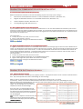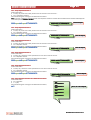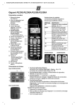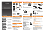
1
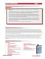
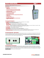
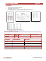
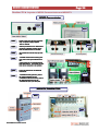
AS300 COMMUNICATOR
SYSTEM MANUAL ALARM
MONITORING
AS300 ALARM SYSTEM
MONITORING
DATA LOGGING
Doc AS300 Communicator Issue 4
Page 2
AS300 ALARM SYSTEM
Table of Contents
IMPORTANT : Section1 must be read before operating the alarm and monitoring system.
1.0
Important Message Please Read
Page 3
6.0
AS300 Communicator Receiver Display
Page 9
7.0
AS300 Communicator Menus
Page 10
7.1
Alarm Menu
Page 10
7.2
System Menu
Page 10
7.3
Transmitter Information Menu
Page 10
8.0
Pin Numbers
Page 10
2.0
AS300 Overview
Page 3
3.0
AS200TX Transmitter
Page 3
3.1
Front Panel Descriptions
Page 4
3.2
Transmitter Power Fail / Battery Low
Page 4
3.3
Battery On Switch / Transmitter Disable
Page 4
3.4
AS200TX Transmitter Inputs
Page 4
3.5
Transmitter Input 1
Page 4
8.1
Set Time and Date in Communicator
Page 10
3.6
Transmitter Input 2
Page 4
9.0
Communicator Initial Setup
Page 11
3.7
Transmitter Input 3
Page 4
9.2
Set Base Number on Communicator
Page 11
3.8
Setup Mode
Page 5
9.3
Register AS200TX Transmitters on to the Communicator
Page 11
3.9
Transmitter Initial Setup
Page 5
10.0
Set Telephone Numbers
Page 12
3.10
Base Setting
Page 5
10.1
3.11
Calibration Reminder Setting
Page 5
Setup Tel No 1 for Transmitter No 1
Page 12
10.2
3.12
Unit Number Setting
Page 5
Setup Tel No 2 for Transmitter No 1
Page 12
10.3
Setup Tel No 3 for Transmitter No 1
Page 12
10.4
Setup Tel No 4 for Transmitter No 1
Page 12
10.5
Setup Tel No 5 for Transmitter No 1
Page 12
10.6
Query Tel Numbers
Page 12
11.0
Set OGM Out Going Message Summery
Page 13
11.1
Setup Out Going Message
Page 13
3.13
Delay Time Setting
Page 5
3.14
High and Low Settings
Page 5
3.15
Quick Setup to Change Parameters
Page 5
3.16
Automatic Self Test Wireless Link
Page 6
3.17
Check Signal Strength
Page 6
3.18
Calibration for Temperature
Page 6
3.19
AS200TC Simulator
Page 6
11.2
Query Out Going Message
Page 13
4.0
AS200TR Transceiver
Page 6
12.0
Lost AS200TX Transmitters
Page 13
5.0
AS300 Communicator Features
Page 7
13.0
Acknowledge Alarms Summery
Page 14
5.1
Front Panel Descriptions
Page 7
13.1
Acknowledge Alarms
Page 14
5.2
Communicator Power / Battery Switch
Page 7
14.0
Query Unit Commands
Page 14
5.3
Lock Password Text Command
Page 7
5.4
Positioning Communicator
Page 8
15.0
Enable / Disable Communicator
Page 16
5.5
Fit SIM Card
Page 8
16.0
Test Alarm
Page 16
5.6
Low Credit Warning
Page 8
17.0.
PAYG / Contract SIMS
Page 16
5.7
GSM Signal
Page 8
18.0
Power Fail Delay Time for Communicator
Page 17
5.8
Antennas
Page 8
19.0
Load Ident on Display
Page 17
5.9
Alarm Sequence when a AS200TX Alarm is Activated
Page 9
20.0
Data Logging and Alarm Log
Page 17
5.10
Telephone Sequence when a AS200TX is Activated
Page 9
21.0
Data Logging Software
Page 19
5.11
Alarm Sequence for Power Fail AS300 Communicator
Page 9
5.12
Telephone Sequence for a AS300 Comm Power Fail
Page 9
22.0
Setup Notes
Page 22
5.13
Test Message
Page 9
23.0
Layouts of AS300 Communicator and AS200TX
Page 23
AS300RX RECEIVER DETAILS
MASTER PIN :
USER PIN :
SIM TEL NUMBER :
SIM NETWORK :
NOTE : This manual uses the master
pin 2222 for demonstrational
purposes.
SERIAL No :
Doc AS300 Communicator Issue 4
AS300 ALARM SYSTEM
Page 3
Section 1 ► THIS SECTION MUST BE READ BEFORE OPERATING THE ALARM SYSTEM
IMPORTANT
To maintain a high level of confidence in the integrity of the complete alarm system it must be tested on a
regular basis.
The responsibility rests with the user as to how often the alarm system is fully tested. This will probably depend on the value of the samples which are being stored in their equipment. The alarm system must be
used only as one aid in the customers overall procedure for protecting their product
All alarm systems are there to assist in the overall protection of your product. Good maintenance of the
monitored equipment is the first line of defence in maintaining the correct operating temperature or environment for your product. All alarm systems have to be checked on a regular basis. Regular checking will find
any faults that have occurred thus improving the overall integrity.
Only O2 and Vodafone PAYG SIMS allow credit response ,which will enable the low credit warnings. All other
networks do not have this facility, so the low credit warnings will not be activated. Please ensure there is
sufficient credit on the SIM card at all times. This will ensure the alarm system will be able to call telephone
contacts in the event of an alarm.
The alarm system must never be used as the primary alarm to protect humans.
Section 2 ► AS300 System Overview
The AS300 system is a new generation of monitoring and alarm systems using the Global System for Mobile Communications
(GSM) and wireless technology. The monitoring and data logging system allows laboratory and hospital equipment to be protected. The system ensures the safety and continued effectiveness of medicine produce, blood products and samples at specific
refrigeration and freezer temperatures. Due to the high value of many of these goods, Quality Assurance programs increasingly
require that storage temperatures are to be verified several times per day and that records be maintained. The AS300 System will
meet the alarm, monitoring and logging requirements.
Make an informed decision on what action to take based on instant readings from the equipment monitored. This can be sent at
any time to your mobile telephone. This is particularly useful if an alarm occurs when the person is on call or out of the workplace. With no need for a dedicated telephone line or line rental the AS300 Communicator is exceptionally easy to install. The
programming of relevant information can be done from any location by a mobile telephone using the relevant password.
Multiple units at different sites can be connected anywhere in the country or countries as the system uses the GSM network of
your choice.
Section 3 ► AS200TX Transmitter
3.0 Features
•
•
•
•
•
•
•
•
•
•
•
•
Compact size. 110H x 65W x 27D (mm)
Simple to use.
•
•
Inputs available : Temperature, and Volt Free Contact.
Temperature range –200°C to +100°C.
Temperature transmitter resolution 0.1°C.
•
•
Temperature transmitter accuracy better than 0.1°C across the full
range.
•
Front panel display of I/P1, temperature , time delay, unit number ID
and alarm parameters.
•
Temperature high and low alarms.
Audible and visual indication of an alarm.
Adjustable time delay for temperature alarm. (0 to 90 minutes)
Mains power failure alarm.
Alarm information sent to the receiver AS300RX, giving details of
transmitter unit and fault.
Doc AS300 Communicator Issue 4
Status and alarm indication on transmitter.
Temperature, high & low alarms and delay time data transmitted
every 15 minutes. This increases to every 10 minutes when in
alarm..
System self test.
Rechargeable battery backup.
Easy calibration procedure / Auto calibration reminder customer
set. Settings ; None, 6 months or 1 year.
Designed bracket for easy installation and positioning.
AS300 ALARM SYSTEM
Page 4
3.1 Front Panel Descriptions.
Switches
Display Switch : Scrolls the display between Unit Number, Time Delay and Temperature. This switch is also used in the setup
procedure.
Mute/Test Switch : When the audible alarm is sounding it can be muted by depressing the switch for one second.
A signal strength test to the receiver can be carried out by depressing this switch for 10 second. This switch is also used in the
setup procedure.
Up/Down Switches : Scrolls the parameter selected to the required value. These switches are also used in the setup procedure.
LED Functions
Alarm Active : Red led flashes when the transmitter is in the alarm condition.
Status : White Led indicating the status of the transmitter.
System ok : Status Light “ON” for 4 seconds and “OFF” for 1 second.
Setup Mode : Status Light flashes rapidly.
Calibration Mode : Status Light and Alarm light flashes rapidly.
Mains Power Fail : Status Light “OFF” for 4 seconds and “ON” for 1 second. (Note in a power fail condition the display is
switched off to conserve battery life).
In Alarm Condition : Status Light “ON” for 1 seconds and “OFF” for 1 second. (A full alarm will only be initiated after the delay
time has elapsed.)
Unit Number : Red led which is illuminated when the display is indicating the transmitter unit number.
Time Delay : Red led which is illuminated when the display is indicating the transmitter time delay for input 1 and input 2.
Temperature : Red led which is illuminated when the display is indicating the transmitter temperature of input 1.
3.2 Transmitter Power Fail/Battery Low
If mains power has been removed from the transmitter unit the system will activate an alarm after a preset 10 minute delay. A
signal will be sent to the receiver. The receiver will indicate the transmitter unit number and AC off. The display on the transmitter is extinguished and the buzzer will sound. This is to preserve the battery life especially useful if the transmitter is used to
log data.
3.3 Battery ON Switch/Transmitter Disable
To locate the battery switch remove the rear compartment flap. The battery On / Off switch is located at the bottom LHS of the
transmitter. To turn the battery ‘ON’ first connect the D.C. power, then place battery switch to the ‘ON’ position. If the battery
switch is not switched on after the DC supply is connected the display will intermittently flash up Bat, reminding the user that
the battery has not been switched on.
To disable the transmitter turn the battery switch to the ‘OFF’ position and remove the DC supply.
Note : If a transmitter is removed from the system, the receiver should be sent a text to re-register the transmitters. This will
remove the transmitter that has been switched off. If this is not done the transmitter will appear as lost after 90 minutes at the
receiver. See Section 9, Para 9.3 to register transmitters.
3.4 Inputs
The Transmitter unit has three inputs labelled I/P1, I/P2 and I/P3.
I/P3 All the input connectors have screw terminals and are accessed by removing the back cover.
3.5 Temperature Input (I/P 1)
Temperature input 1 uses a PT1000 probe. The value of this input is displayed on the front panel when temperature is selected. The input range is +100°C to –200°C with an instrument accuracy of 0.1°C. This input is usually used as the main air
temperature alarm input. This input has an adjustable time delay of between 0 and 90 minutes.
3.6 Temperature Input (I/P 2) (Option)
Temperature input 2 uses a PT1000 probe. The input range is +100°C to –200°C with a instrument accuracy of 0.1°C. This
input is usually used as an auxiliary input and is mainly used to measure
product temperature. The time delay for this input mirrors the time delay
set for I/P1.
3.7 Volt Free Contact Input (I/P 3) (Option)
Volt free input 3 can be used to monitor any “normally closed” contact.
This input is normally used as a door switch monitor.
Normally “closed” position = No alarm
Normally “open” position = alarm
This input has a fixed time delay of 10 minutes.
Doc AS300 Communicator Issue 4
AS300 ALARM SYSTEM
Page 5
3.8 Setup Mode
To change the parameters on the AS200TX transmitter the unit must be placed in
the setup mode. This is achieved by depressing the setup switch which is located
at the top right hand side of the transmitter through a small hole. Depression of
this switch is achieved using a pin or paper clip.
3.9 Transmitter Initial Setup
The setting of the base number, calibration reminder, unit number, time delay and
high & low alarms are carried out in one complete sequence. The sequence must
be completed to return the transmitter to its normal operating condition. The white
status led will flash rapidly in setup mode, this will return to solid for 4 seconds on,
1 second off in the normal OK condition once setup mode is completed. If the
transmitter is left in the setup mode it will return to normal mode after approximately 3 minutes. To place the transmitter into the setup mode the setup switch is
depressed, this is accessed by a small pin or paper clip. Access to this switch is
located at the top right hand side of the transmitter.
3.10 Base Number Setting
Depress the setup button once, located at the top of the transmitter (Small hole). This will require the end of a paper clip or
pen pushed through the small hole.
When in setup mode the white status led will flash rapidly.
Depress the mute button three times and the display will show BASE. Use the up and down arrows to set the base on the
transmitter to the same base as the receiver. (Up to 15 bases are available, factory default is Base 1). Once this has been
done press the Mute switch to register this value.
3.11 Calibration Reminder Setting
Depress the display switch and the calibration reminder mode will be entered, CAL is displayed. This will now set up the frequency for CAL being shown on the display. By depressing the up and down arrows this can be set for No CAL, 6 monthly or
12 monthly. Once the required value is selected depress the mute switch to register this value. (Factory Default No Cal)
3.12 Unit Number Setting
Depress the display switch, the unit number led is illuminated. The unit number can be changed by depressing the up and
down arrows. Select a number between 1 and 90 dependant on receiver range setting. Once the required value is selected,
depress the mute switch to register the value.
3.13 Delay Time Setting
Depress the display switch, the time delay led is illuminated. The time delay can be changed by depressing the up and down
arrows. Select a number between 0 and 90 minutes. Once the required value is selected, depress the mute switch to register the value.
3.14 High and Low Alarms
Depress the display switch, the temperature led is illuminated, HIAL is displayed momentary. The temperature high alarm can
be changed by depressing the up and down arrows. Select a number between 100 and –200, the display will scroll very fast.
Once you are near the required value depress the mute switch. Depress the display switch and FINE will be momentarily
displayed. Depress the up or down arrows to select your actual high alarm set-point and depress the mute switch to register
the value.
The display switch is again depressed now entering the low alarm mode LOAL is displayed momentary. The temperature low
alarm can be changed by depressing the up and down arrows. Select a number between 100 and –200, the display will
scroll very fast. Once you are near the required value depress the mute switch. Depress the display switch and FINE will be
momentarily displayed. Depress the up or down arrows to select your actual low alarm set-point and depress the mute switch
to register the value.
The status led will now stop flashing rapidly to indicate that the transmitter is back in normal mode.
3.15 Quick Setup to change Unit number, Time Delay or High and Low alarms.
The changing of the unit number, time delay and high & low alarms are carried out in one complete sequence. The sequence
must be completed to return the transmitter to its normal operating condition. The white status led will flash rapidly in setup
mode and will return to solid for 4 seconds on, 1 second off in the normal OK condition. If the transmitter is left in setup
mode it will return to normal mode after approximately 3 minutes.
Depress the setup button once, located on the top of the transmitter. (Small hole) This will require the end of a paper clip or
pen pushed through the small hole.
When in setup mode the white status led will flash rapidly, start from para 3.12 to para 3.14.
Doc AS300 Communicator Issue 4
AS300 ALARM SYSTEM
Page 6
3.16 Automatic Self Test Wireless Link
The system will automatically test its communications between the transmitter’s and the receiver every 15 minutes.
If the receiver has not received a signal from a transmitter, a lost alarm will be generated after 90 minutes at the Communicator.
3.17 Check Signal Strength.
The transmitter can be forced to send a test signal to the Communicator. This is achieved by depressing the Mute/Test Switch
for 10 seconds. No alarms will be activated at the Communicator upon receipt of a test signal. The display will show the unit
number and strength of the signal.
This should be used when installing the system and when a transmitter is moved to a new location. The test display is removed from the receiver by depressing the Mute switch on the receiver. The display will then revert back to the scrolling menu,
this can take up to 15 seconds.
3.18 Calibration for Temperature
To locate the calibration switch remove the rear compartment flap. The calibration switch is located to the left hand side above
the battery switch. Remove the temperature probe from the input and attach the AS200-TC to simulate the temperature probe.
The simulated probe resistance is set at 1000Ω, which accurately simulates 0°C. The calibration of the instrument displays a
resistance measurement which now can be adjusted by the up and down switches. The value required is 999.9 or 0.0 this
adjustment is made by the up and down switches.
Once adjusted the accuracy of the instrument can be checked by switching the calibration switch off. The temperature should
now read 0.0°C If a AS200TS simulator is used, +50°C and –50°C can easily be checked. Remove the AS200-TC and replace
with the temperature probe.
The AS200TX is a very stable instrument and will rarely require calibration. It is recommended that the AS200TX is checked by
simulating several temperatures to ensure it is within calibration parameters. This can easily be achieved by using the
AS200TC temperature simulator.
3.19 AS200TC Simulator
Test temperatures at +50.0°C, 0.0°C and -50.0°C can be simulated on transmitter input 1 to test the alarm.
The temperature simulator unit is attached to input 1 once the temperature probe is removed. The simulated
temperature is selected and will be shown on the display. If this temperature is out with the alarm limits it will
activate the relevant alarm after the time delay.
The resistance to simulate 0.0C can be supplied with a traceable calibration certificate. This can be used to
calibrate the AS200TX transmitter
Section 4 ► AS200TR Transceiver
4.0 AS200TR Transceiver
The transceiver unit is used to increase the distance between a transmitter and the Communicator, if required. There is no limit to the number of transceivers that can be used in a system.
The transceiver is powered by an external DC supply and has a rechargeable battery fitted as standard. If
power fail is detected on the transceiver an alarm will be sent to the receiver initiating an alarm condition.
Doc AS300 Communicator Issue 4
AS300 ALARM SYSTEM
Page 7
Section 5 ► AS300 Communicator
5.0 Features
• Compact size. 170H x 85W x 35W (mm)
• Simple to use.
• 100 Transmitter channels, one transmitter per channel.
• Three menus available giving information on the system.
• Last 10 alarms stored.
• All alarms are time and date stamped.
• Acknowledged by mobile phone.
• Up to five telephone numbers.
• Add and remove transmitters by a simple password protected text.
• Audible alarm.
• Power failure alarm.
• Rechargeable battery backup.
• Built in communications to mobiles, land lines and web.
• Logged data to web. (Option)
5.1 Front Panel Descriptions.
● Unit Enabled : - Green LED when the unit is enabled. Red LED when unit is disabled.
● Status :- LED indicating the status of the unit.
● System OK: - “ON” for 4 seconds and “OFF” for 1 second.
Mains Power Fail : - Status Light “OFF” for 4 seconds and “ON” for 1 second.
In Alarm Condition : - Status Light “ON” for 1 seconds and “OFF” for 1 second.
GSM Signal : - Indicates signal strength. LED will be solid and flash every 1 minute. Four flashes indicate a excellent signal
strength. This LED will be extinguished if a weak signal is detected.
●
●
●
●
●
●
Credit Required : - “ON” when SIM value drops below £4.00.
Alarm Activated : - “ON” when alarm is activate.
Power Failed :- “ON” when power fail is activate after delay time.
Alerts In Progress :- “ON” when alarm alerts and acknowledgments are being sent.
Display :- The display scrolls through information on system e.g GSM Signal strength and credit on sim (See Section 6)
Scroll and Menu Switches :- Allows access to Alarm, System, Probe and TX Info menus (See section 7)
5.2 Communicator Power – Battery Switch
Use only the supplied power supply for the receiver and connect the 12V d.c. 2.1mm socket to the power input located at the
base of the AS300 Communicator To locate the battery switch remove the rear compartment flap. The battery On / Off switch
is located at the bottom left hand side of the communicator. If mains power has been removed from the Communicator the
system will activate an alarm after the programmed delay time.
5.3 Lock Password Text Commands
For added protection, once the relevant procedures including telephone numbers, messages etc have been set up, internal
switch 3 (ENG TYPE) can be switched into the ON position (Factory Shipped OFF position). This will not allow any setting to be
changed with a master pin number until this switch is returned to the OFF position. The unit can be queried for information with
the switch in the ON position. If the master pin is used for a text command whilst switch 3 is in the ON position, the message
Access Denied will be sent from the Communicator.
Doc AS300 Communicator Issue 4
AS300 ALARM SYSTEM
Page 8
5.4 Positioning Communicator
The choice of Communicator site affects the ultimate system performance; this can be important if transmitters are positioned at the
limit of their range or in buildings were significant metal is used in their construction (such as reinforced concrete containing metal
rods), or utilising metal internal partitioning.
For maximum range coverage and reliability the Communicator should be located in a central position with respect to the transmitters. In general, the higher the Communicator, the better the range achieved. To avoid screening effects, the Communicator should
be mounted well away from large metal masses such as metal filing cabinets. The Communicator should be mounted at least 1.5
metres above ground level and positioned at least 1 metre away from mains electrical panels, electricity cables and sources of high
speed switching, such as computers, otherwise radiated electrical noise may reduce the Communicator sensitivity.
If these instructions are not carried out the Communicator will have reduced sensitivity and possible future problems can occur such
as lost transmission of transmitter units.
Common mistakes when positioning a receiver
1. Communicator is positioned in receptions or gate houses where there is considerable communications equipment.
2. Communicator is positioned close to electricity cables beneath the wall surface. Check position of electricity sockets and light
switches. Cables from these items will be run vertically or horizontally. Do not locate the Communicator within 0.5 metre of these
cables.
3. Communicator is positioned in a basement.
5.5 Fit the SIM Card
If a sim card had not been ordered with the receiver,
please fit a sim card. A Pay As You Go or contract
sim card can be used in the receiver. The Communicator is set up for a “Pay As You Go” sim card by
default. If a contract sim card is used the low credit
warnings must be disabled in the GSM Unit as many
contract sims display a £0.00 balance when interrogated by the unit. To change SIM settings please
see Section 17.0.
The sim number and credit will be displayed on the main scrolling display.
TOP UP PAYG SIM Card
There are several methods of topping up the credit on a PAYG sim card.
1. The simplest method is to use a cash point machine which displays the sign TOP UP MOBILE HERE, these machine also issues a
receipt of the transaction.
2. The internet can be used, go to the network of the sim card web site.
5.6 Low Credit Warnings for Pay as you go Sim Card
If the credit on the SIM Card falls below £4.00 the Credit Required LED will be illuminated and the buzzer will bleep every 60 minutes.
If the credit on the SIM Card falls below £2.00, Credit Required LED will flash and a text message will be sent to Communicator telephone number 1.. The message is “GSM Alarm credit low”, this will be repeated every 7days until the SIM has been topped up.
NOTE :-:- NOT ALL MOBILE NETWORKS PROVIDE INFORMATION ON THE CREDIT LEVEL OF THE SIM WHICH MAKES THIS FEATURE UNRESPONSE..
USABLE . ONLY O2 & VODAFONE PAYG SIMS HAVE A CREDIT RESPONSE
5.7 GSM Signal
The AS300 Communicator unit must have a GSM signal to operate. The signal strength is shown in two ways on the unit.
1.
2.
3.
4.
The scrolling display will show signal strength and credit on sim.
The GSM Signal LED will be lit solid and will flash every one minute. Four flashes indicates a good signal.
If no signal or a poor signal is present the unit will sound its audible alarm. This can be muted but will keep resounding every
10 minutes to remind the user that their alarm is not operational. Action should be taken to rectify this problem by moving
the unit or changing the network provider.
If no Sim card is present in the unit the GSM Signal LED will turn red.
5.8 Antennas
The Communicator GSM and radio antennas must be screwed into position
for the AS300 Communicator to operate. The GSM antenna is located at the
top right hand side and the wireless antenna is located at the top towards the
left hand side. The Antenna’s both use SMA connections.
If reception is weak for either the wireless or GSM signal, larger antenna’s are
available.
Doc AS300 Communicator Issue 4
AS300 ALARM SYSTEM
Page 9
5.9 Alarm Sequence at the AS300 Communicator when a AS200TX transmitter alarm is activated.
When an alarm is activated the following sequence is started :-
1. Status led flashes.
2. Alarm Activated LED is illuminated and NEW ALARMS are displayed on the LCD display.
3. Audible alarm sounds.
4. Audible alarm can be muted by pressing the mute button or an acknowledgement text from a mobile telephone.
5. Telephone sequence starts.
6. Alerts sent, LED is illuminated.
7. Once acknowledged Alarm Activated and Alerts Sent LED are extinguished (once all alerts are sent).
5.10 Alarm Telephone Sequence for AS300 Communicator when a AS200TX transmitter alarm is activated.
When an alarm is activated after the delay time set, it will telephone number 1 then 2, 3, 4 and 5 respectively. A delay of 3 minutes is allowed between each call for the recipient of the call to acknowledge the alarm. When the call has been acknowledged
no more calls are made and all recipients of the alarm call will receive a further call to alert them that the alarm has been acknowledged. This acknowledged call will contain the telephone number of the acknowledger.
If the alarm call is not acknowledged the telephone numbers will be repeated with the alarm call. To minimise cost and annoyance of these calls, the time interval between each call doubles each time a sequence is phoned. So in the first instance it is 5
minutes, then 10 minutes, then 20 minutes and so on.
5.11 Alarm Sequence for a AS300 Communicator in Power Fail.
When a receiver power fail alarm is activated the following sequence is started :-
1. Power Failed LED is lit and NEW ALARMS are displayed on the LCD display.
2. Audible alarm sounds.
3. Audible alarm can be muted by pressing the mute button or an acknowledgement from a mobile telephone.
4. Telephone sequence starts.
5. Once power is restored power fail led flashes. To extinguish this LED press the Mute /Clear button until the buzzer bleeps.
5.12 Alarm Telephone Sequence for AS300 Communicator in Power Fail Alarm.
When an alarm is activated from a power fail at the Communicator, telephone number 1 will be sent then the remaining telephone numbers if entered will be sent at 3 minute intervals. If these calls are not acknowledged Tel 1 to Tel 5 will be phoned
again 30 minutes later. After this no more phone calls will be issued until power is resumed.
5.13 Test Message
The AS300 Communicator will send a test message to telephone number 1 (Tel1)
Tel1) every 28 days. This feature helps to ensure
the communications of the unit are working and if a PAYG sim is fitted, keeps the network active for the sim. The time of the test
message is derived from when the unit is powered up.
Section 6 ► AS300RX Display
1. The Version number of the firmware is
displayed, followed by the AS Config then
RX100 Receiver
3. Sim check is now done if a sim is fitted
SIM OK will be displayed. If no sim is fitted
“No Sim” will be displayed followed by best
network available. The unit will stop at
this point until a sim is fitted.
5. The strength of the GSM signal will be
displayed.
7. The display will now start scrolling, starting with information as described 7 to 12.
The sim card telephone number fitted. If
O2 or Vodafone sims are not used the
display will read SIM No, UNAVAILABLE.
UNAVAILABLE
9. The total number of AS200TX transmitters registered on the system, after the
registration period.
Doc AS300 Communicator Issue 4
Ver 283U1
V12
SIM OK
Signal
Full
2. Please wait, is displayed.
4. The network of the sim will be
displayed.
6. The AS300 Communicator is now
started and ready to use.
Please
Wait
SIM OK
O2
Unit
Started
07456
856325
8. The GSM signal strength and
credit available on the sim installed.
Only O2 and Vodafone will give
credit information.
information
SIG FULL
CR=1000p
Total No
Txs : 8
10. The base number and transmitter unit range of the AS300 Communicator.
Base 1
TX1
TX1--100
AS300 ALARM SYSTEM
11
11. The time and date will be displayed. If this requires to be set up
please see Section 20.1.
Page 10
14:02
30/05/11
12. Load Indent will be displayed if
the sim used is not an O2 or Vodafone. An indent can be registered
on the display see Section 19.0
LOAD
IDENT
Section 7 ► AS300 Communicator Menus
7.0 Menus
The menu button will allow the user to access three menus, alarm menu, system menu and tx info menu. Once the desired
menu has been selected, use the scroll button to scroll through this menu.
7.1 Alarm Menu
The alarm menu will show the last 10 alarms showing the most recent alarm first. The alarms are time and date stamped and
the first alarm will show the number 1 up to 10 for the tenth alarm. An asterisk will follow the alarm number if it has not been
viewed before. Once viewed the asterisk will be removed, by scrolling to the next display it will show the date of the alarm.
Scroll
Scroll for
for this
this screen
screen
ALARM
MENU
Tx 3 IP1
01*11:05
Alarm
Alarm number
number
Time
Time of
of alarm
alarm
Tx 3 IP1
09/03/11
Date
Date of
of alarm
alarm
7.2 System Menu
The system menu will show the serial number of the AS300 Communicator and the current time and date set in the AS300
Communicator.
SYSTEM
MENU
SN : 1048
16:42
06/04/12
7.3 Transmitter Information Menu
TX INFO
MENU
BASE No
1
Total No
Txs 9
The Tx Info menu will show the base number and the
number of transmitters registered on to the AS300
Communicator.
Section 8 ► Pin Numbers / Set Time and Date
8.0 Pin Numbers
The AS300 Communicator uses two pin numbers, the master pin allows settings to be changed e.g. alarms, telephone numbers
etc and the users pin allows alarms to be acknowledged and certain parameters to be queried for information. For convenience no pin number is required for certain texted commands and queried information.
For added protection, once the relevant procedures including telephone numbers, messages etc have been set up, internal
switch 3 (ENG TYPE) can be switched into the ON position. This will not allow any setting to be changed with a master pin number until this switch is returned to the OFF position (See Fig 4) Section 23.0. The unit can be queried for information with the
switch in the ON position. If the master pin is used for a text command whilst switch 3 is in the ON position, the message
Access Denied will be sent from the Communicator.
8.1 Set Time and Date in the Real Time Clock
The real time clock is required to be set up in the Communicator to give accurate readings of time and date.
Example for setting 19th January 2010, 1:45pm (13:45) and 30 seconds.
Send the following text message to the AS300 Communicator
2222spaceclockspace19/01/11,13:45:30
Doc AS300 Communicator Issue 4
Page 11
AS300 ALARM SYSTEM
Section 9 ► COMMUNICATOR SYSTEM INITIAL SETUP
9.0 Communicator System Initial Setup Summary
Before the AS300 Communicator can be used the following requires to be setup by text message :-
•
•
•
•
Base Number of the AS300 Communicator to match the AS200TX transmitters. (Ref Section 9.2)
Register the AS200TX transmitters on to the AS300 Communicator. (Ref Section 9.3)
Contact Telephone Numbers. (Ref Section 10)
Out Going Message, OGM. (Ref Section 11)
9.1 Set the Base Number on the Communicator
Up to 15 different bases can be set for the receiver numbered from 1 to 15. This allows AS300 Communicator system to be located near to each other without interfering with one another. The transmitters and Communicator have to be configured to the
same base number to allow the AS200TX transmitters to be registered on to the AS300 Communicator unit. The Communicator
will be factory set for Base No 01.
Setup information :♦ To setup any values the master pin has to be used.
♦ base 1= base number 1 to be set.
Send the following text message to the AS300 Communicator,
2222spacebase1
2222 base1
Master
Master Pin
Pin Required
Required
9.2 Register the AS200TX transmitter on to the AS300 Communicator
To register the AS200TX transmitters on to the AS300 Communicator a text message regtx has to be sent to the AS300 Communicator. This will allow the communicator to look for transmitters for 90 minutes. Once the 90 minutes has expired no new transmitters will be accepted on to the communicator. To add or remove AS200TX transmitters from the AS300 Communicator the
same procedure should be carried out. Transmitters which require to be removed from the system must have their power removed and battery switched off before this procedure is carried out.
Setup information :♦ To setup any values the master pin has to be used.
♦ regstr= register AS200TX transmitters on to the AS300 Communicator.
♦ regend = ends registration period before 90 minutes has elapsed.
Send the following text message to the AS300 Communicator.
Master
Master Pin
Pin Required
Required
2222 regstr
2222spaceregstr
2222spaceregend
2222 regend
Master
Master Pin
Pin Required
Required
Section 10 ► Set Telephone Numbers
10.0 Telephone Numbers Summary
The AS300 Communicator will accept up to 5 telephone numbers. The telephone numbers can be a mixture of mobile and land
lines. Only mobile phones will be able to acknowledge an alarm message.
When an alarm is activated after the delay time set, it will telephone number 1 then 2, 3, 4 and 5
consecutively. A delay of 3 minutes is allowed between each call for the recipient of the call to acknowledge the alarm.
When the call has been acknowledged no more calls are made and all recipients of the alarm call will receive a further call to
alert them that the alarm has been acknowledged. This acknowledged call will contain the
telephone number of the acknowledger.
If the alarm call is not acknowledged the telephone numbers will be repeated with the alarm
call, firstly with 5 minutes between the sequence
and then doubling the time on every sequence if
not acknowledged.
Tel1 must have a telephone number entered. If no
telephone number is entered here the AS300
Communicator LCD display will intermittently show
*INSERT* RXTEL1*.
RXTEL1*
Doc AS300 Communicator Issue 4
Page 12
AS300 ALARM SYSTEM
10.1 Setup Telephone Number 1
Useful information :♦ To setup any values the master password has to be used in front of the text .
♦ tel1 = Telephone number 1
Send the following text message to the AS300 Communicator.
Tel1 must have a telephone number entered. If no telephone number is entered here the AS300 Communicator LCD display will
intermittently show *INSERT* RXTEL1*.
RXTEL1*
2222spacetel1space07742663872
2222 tel1 07742663872
10.2 Setup Telephone Number 2
Useful information :♦ To setup any values the master password has to be used in front of the text .
♦ tel = Telephone number
Send the following text message to the AS300 Communicator.
2222spacetel2space07742663873
2222 tel2 07742663873
10.3 Setup Telephone Number 3
Useful information :♦ To setup any values the master password has to be used in front of the text .
♦ tel = Telephone number
Send the following text message to the AS300 Communicator.
2222spacetel3space07742663874
2222 tel3 07742663874
10.4 Setup Telephone Number 4
Useful information :♦ To setup any values the master password has to be used in front of the text .
♦ tel = Telephone number
Send the following text message to the AS300 Communicator.
2222spacetel4space07742663875
2222 tel4 07742663875
10.5 Setup Telephone Number 5
Useful information :♦ To setup any values the master password has to be used in front of the text .
♦ tel = Telephone number
Send the following text message to the AS300 Communicator.
2222spacetel5space07742663876
2222 tel5 07742663876
10.6 Query Telephone Numbers set in AS300 Communicator
Useful information :♦ tel = Telephone
♦ ? = Query
Send the following text message to the AS300 Communicator,
tel?
Tel1
07742663872
Tel2
07742663873
Tel3
07742663874
Tel4
07742663875
Tel5
07742663876
Master
Master Pin
Pin Required
Required
Master
Master Pin
Pin Required
Required
Master
Master Pin
Pin Required
Required
Master
Master Pin
Pin Required
Required
Master
Master Pin
Pin Required
Required
Master,
Master, User
User or
or No
No Pin
Pin Required
Required
Doc AS300 Communicator Issue 4
Page 13
AS300 ALARM SYSTEM
Section 11 ► Set Out Going Message (OGM)
11.0 Out Going Message Summary
When an alarm is activated, a message will be sent to the recipients on the telephone list. If the message is sent to a mobile
telephone it will be in the form of a text message. If it is sent to a land line it will be processed as a synthesised voice message.
The OGM can be up to 80 characters long, messages longer than this will be rejected by the AS300 Communicator. To check
which transmitter has alarmed, text Alarms? to the Communicator. This will send a message listing the last 5 alarms recorded.
11.1 Setup Out Going Message
Useful information :♦ To setup any values the master pin has to be used.
♦ OGM = Out Going Message ( NOTE : OGM has to be in upper case)
Send the following text message to the AS300 Communicator,
2222spaceOGMspace-80C freezer No 16, Dr J Trident,
2222 OGM -80C freezer No 16, Dr
J Trident, Room 235, Cell Research,
Thomas Building, Leeds
Room 235, Cell Research, Thomas Building, Leeds
Master
Master Pin
Pin Required
Required
11.2 Query Out Going Message set in AS300 Communicator.
When a outgoing message is set or changed in the Cpmmunicator a text message will be sent to the mobile which changed the
message. This should be checked to make sure the message has been entered correctly.
Useful information :♦ To query any values the master pin has to be used.
♦ OGM = Out Going Message
♦ ? = Query
2222spaceOGM?
Master,
Master, User
User or
or No
No Pin
Pin Required
Required
OR
OGM?
2222 OGM?
OGM?
Section 12 ► Lost AS200TX Transmitters
12.0 Lost of transmission from a AS200TX Transmitter
If the AS300 Communicator does not receive a transmission from a AS200TX transmitter registered on the system between 90
to 180 minutes, a lost transmitter alarm will be generated. The Communicator will log the alarm in the alarm menu and NEW
ALARMS will be displayed on the Communicator LCD display. The sounder will be activated and a text will be sent if “txlost is
on”. If “txlost is off” no text or sounder will be activated. The lost alarm text message is enabled as default but can be disabled
if required.
To turn OFF lost AS200TX transmitter message.
Useful information :♦ To setup any values the master pin has to be used.
♦ Txlost off = turns text message off for lost AS200TX transmitters.
Send the following text message to the AS300 Communicator
2222 txlost off
2222spacetxlostspaceoff
To turn ON lost AS200TX transmitter message.
Useful information :♦ To setup any values the master pin has to be used.
♦ Txlost on= turns text message on for lost AS200TX transmitters.
Send the following text message to the AS300 Communicator
2222spacetxlostspaceon
Doc AS300 Communicator Issue 4
2222 txlost on
Master
Master Pin
Pin Required
Required
Master
Master Pin
Pin Required
Required
AS300 ALARM SYSTEM
Page 14
Section 13 ► Acknowledge Alarms
13.0 Acknowledge Alarms Summary
When an alarm is activated, it has to be acknowledged before it will stop sending out the alarm text. Once
acknowledged, recipient’s who have received the alarm text will be sent a text giving telephone details of the acknowledger.
Acknowledging of alarms can be carried out by the master password, acknowledgers password or simple ack text. At the end of
the alarm text message a prompt will tell the user the correct acknowledgement text to use. Once the alarm has been acknowledged the Alarm Activated Led will be extinguished and the sounder will be silenced. The AS300 Communicator alarm sounder
can also be silenced by depressing the mute button on the front panel of the Communicator. The LCD on the AS300 Communicator will display NEW ALARMS . On power fail of the Communicator the front panel led’s are extinguished to conserve battery
life apart from Power Fail. When the power has been restored and alarm acknowledged, press the Mute Button to extinguish
the power fail Led.
13.1 Acknowledge Alarm
An alarm can be acknowledged with any of the following texts to the alarming unit.
Useful information :♦ ack = acknowledge alarm
Send the following text message to the AS300 Communicator.
2222spaceack
OR
Ack
2222 ack
ack
Master,
Master, User
User or
or No
No Pin
Pin Required
Required
A message will be sent back to the mobile telephone will contain the following details
Alert reset by
07742663876
The telephone number which acknowledged the alarm.
NOTE
On power fail of the Communicator the front panel led’s are extinguished to conserve battery life apart
from Power Fail. When the power has been restored and alarm acknowledged, press the Mute Button
to extinguish the power fail Led.
Section 14 ► Query Unit Commands
14.0 Query Unit Commands
When information is required from a AS200TX transmitter or the AS300 Communicator, the AS300 Communicator can be queried. A list of the most commonly used queries are listed in this section. The user can select a master pin number in front of the
message which in some queries gives more information.
14.1 Query Base Value in the Communicator
This will send back to the users mobile telephone the Base number set in the AS300 Communicator.
Setup information :♦ base= base setting in the AS300 Communicator.
♦ ? = query
Send a text a message to the AS300 Communicator,
Master,
Master, User
User or
or No
No Pin
Pin Required
Required
base?
base?
Doc AS300 Communicator Issue 4
Page 15
AS300 ALARM SYSTEM
14.2 Query Registered Transmitters in the Communicator.
This will send back to the users mobile telephone, the transmitters registered on the AS300 Communicator.
Setup information :♦ regtx= registered AS200TX transmitters on the AS300 Communicator.
♦ ? = query
Send a text a message to the AS300 Communicator,
Master, User or No Pin Required
regtx?
regtx?
Master, User or No Pin Required
14.2 Query Active Transmitters in the Communicator.
This will send back to the users mobile telephone, the transmitters which are active on the AS300 Communicator.
Setup information :♦ actx?= active AS200TX transmitters on the AS300 Communicator.
♦ ? = query
Master,
Master, User
User or
or No
No Pin
Pin Required
Required
Send a text a message to the AS300 Communicator,
actx?
actx?
4.3 Query Alarm Log in the Communicator.
This will send back to the users mobile telephone, the last five alarms logged.
♦ alarms= the last five logged alarms in the AS300 Communicator.
♦ ? = query
Send a text a message to the AS300 Communicator,
alarms?
alarms?
Master,
Master, User
User or
or No
No Pin
Pin Required
Required
14.4 Query AS200TX Transmitter Values.
This will send back to the users mobile telephone the current values in the transmitter.
♦ tx7= current values in transmitter unit number 7, including current temperature.
♦ ? = query
Send a text a message to the AS300 Communicator,
tx7?
tx7? Note : Master pin returns more information
Master,
Master, User
User or
or No
No Pin
Pin Required
Required
14.6 Query Communicator Telephone Numbers.
This will send back to the users the telephone numbers stored for the AS300 Communicator.
♦ tel= the telephone numbers stored in the AS300 Communicator.
♦ ? = query
Send a text a message to the AS300 Communicator,
Master,
Master, User
User or
or No
No Pin
Pin Required
Required
tel?
tel?
14.7 Query OGM Outgoing Message.
This will send back to the users mobile telephone the Out Going Message. (OGM is case sensitive)
♦ OGM= the outgoing message set in the Communicator, this message will be sent in the event of an alarm.
♦ ? = query
Send a text a message to the AS300 Communicator,
OGM?
OGM?
Master,
Master, User
User or
or No
No Pin
Pin Required
Required
time?
Master,
Master, User
User or
or No
No Pin
Pin Required
Required
14.9 Query Time and Date Stored in the Communicator.
This will send back to the users mobile, the time and date set in the receiver.
♦ time= the current time and date set in the communicator.
♦ ? = query
Send a text a message to the AS300 Communicator,
time?
Doc AS300 Communicator Issue 4
AS300 ALARM SYSTEM
Page 16
Section 15 ► Enable / Disable Communicator
15.0 Enable / Disable Overview
The AS300 Communicator can be enabled or disabled from a mobile text command. When the unit is in the disabled mode no
alarm reporting will take place, in the enabled mode all alarms will be reported. An illuminated green LED indicates the unit is
enabled and in the disabled mode this LED is red. The unit can be sent query messages in the disabled mode.
15.1 Enable Unit
Useful information :♦ To setup any values the master pin has to be used.
♦ enable = enable Unit.
Send the following text message to the AS300 Communicator,
2222spaceenable
2222 enable
Master
Master Pin
Pin Required
Required
15.2 Disable Unit
Useful information for setting an alarm.
♦ To setup any values the master pin has to be used.
♦ disable = disable Unit.
Send the following text message to the AS300 Communicator,
2222spacedisable
2222 disable
Master
Master Pin
Pin Required
Required
Section 16 ► Test Alarm
16.0 Test Alarm Summary
The test alarm function will send the full OGM to all the telephone numbers. The message will have test at the end of the OGM.
The test alarm has to be acknowledged to stop the test.
16.1 Test Alarm
Useful information :♦ To setup any values the master pin has to be used.
♦ test = test alarm unit.
Send the following text message to the AS300
Communicator,
2222 test
2222spacetest
NOTE
To acknowledge a test alarm
use text message ack
Master
Master Pin
Pin Required
Required
16.2 Test Message
When the AS300 Communicator is powered up, the time and date is recorded into memory. Every 28 days from this time a test
message will be sent to receiver telephone number 1.
Section 17 ► PAYG / Contact Sim Card Setup
17.0 PAYG / Contact Sim Card Setup
The AS300 Communicator is set up for a “Pay As You Go” sim card by default. If a contract sim card is used the low credit warnings must be disabled in the GSM Unit as many contract sims display a £0.00 balance when interrogated by the unit which will
set off alarms.
17.1 Setup Contact Sim
Useful information :♦ To setup any values the master pin has to be used.
♦ CONT = set AS300 Communicator for contact sim. (CONT uppercase)
Send the following text message to the AS300 Communicator,
2222spaceCONT
2222 CONT
Master
Master Pin
Pin Required
Required
17.1 Setup PAYG Sim
Useful information :♦ To setup any values the master pin has to be used.
♦ PAYG = set AS300 Communicator receiver for PAYG sim.
Send the following text message to the AS300 Communicator
2222spacePAYG
2222 PAYG
Master
Master Pin
Pin Required
Required
Doc AS300 Communicator Issue 4
AS300 ALARM SYSTEM
Page 17
Section 18 ► Power Fail Delay Time in AS300 Communicator
18.0 Power Fail Delay Time
To set the delay time before a power fail alarm is activated at the Communicator.
Useful information for setting an alarm.
♦ To setup any values the master pin has to be used.
♦ PWR = power fail.
♦ 10 = time delay in minutes.
Send the following text message to the AS300 Communicator,
2222spacepwrspacetd10
2222 pwr td10
Master
Master Pin
Pin Required
Required
Section 19 ► Load Ident on Display
19.0 Load Ident on Display
The Load Ident will be shown on the display if the sim card used is not an O2 or Vodafone sim. If a O2 or Vodafone sim
card is used the telephone number of the sim card will be shown instead of load Ident. To load an ident in the AS300
Communicator text a message to the AS300 Communicator unit.
Example for setting the ident to SIM 07565627811.
Send the following text message to the AS300 Communicator
*#*# IDENT SIM 0756;5627811
*#*#spaceIDENTspaceSIMspace0756;5627811
Section 20 ► Data Logging & Alarm Log
20.0 Data Logging and Alarm Log Overview
The AS300 Communicator can log data which can be sent to a server, this data can be down loaded to a computer and
stored. This downloaded data can be analysed using the Data Analysis Software. The data interval stored from the transmitters are every 15 minutes. The alarm log gives details of all alarms, listing alarm input, time, date, call direction, telephone number, acknowledgers number and whether the call was successful or failed.
To activate this service please contact your supplier or visit www.asper.co.uk/Webserver.htm (Register for Logging)
20.1 Set Time and Date in the Real Time Clock
The real time clock is required to be set up to give accurate readings of time and date, two methods are available
Method 1
Example for setting 19th January 2010, 1:45pm (13:45) and 30 seconds.
Send the following text message to the AS300 Communicator
2222 time 19/01/11,13:45:30
2222spacetimespace19/01/11,13:45:30
Master
Master Pin
Pin Required
Required
The time sent should be approx 1 minute ahead of the current time. The time sent will be displayed on the LCD display
and the buzzer will start beeping. Check the real time on an accurate clock e.g. mobile phone or computer. When the
current time matches the displayed time, press the mute button on the AS300 Communicator. The real time clock will
now be set to the correct time.
Method 2
Example for setting 19th January 2010, 1:45pm (13:45) and 30 seconds.
Send the following text message to the AS300 Communicator
2222spaceclockspace19/01/11,13:45:30
2222 clock 19/01/11,13:45:30
2222 clock 19/01/11,13:45:30
Master
Master Pin
Pin Required
Required
The time will now be set in the unit.
20.2 Query Date & Time in the AS300 Communicator
This will query the current time and date in the AS300 Communicator.
♦ time= time and date set in the AS300 Communicator.
♦ ? = query
Send a text a message to the first AS300RX receiver with the following text.
time?
Doc AS300 Communicator Issue 4
time?
Master,
Master, User
User or
or No
No Pin
Pin Required
Required
Page 18
AS300 ALARM SYSTEM
20.3 Change Logging Time
The data logged time interval can be changed by a text command to the Communicator. The more data stored will impact on the
cost to send the data to the server, a good compromise is every 30 minutes.
Useful information for setting an alarm.
♦ To setup any values the master pin has to be used.
♦ STDL = data logged time
♦ 30 = logging time interval
Master
Master Pin
Pin Required
Required
2222 STDL 30
Send the following text message to the AS300 Communicator,
2222spaceSTDLspace30
20.4 Initiate a Current Download of Data
The data is sent to the server every 24 hours, if current data is required since the last download, send a text a message to the
AS300 Communicator.
Useful information for setting an alarm.
♦ To setup any values the master pin has to be used.
♦ DNLD = download data (DNLD upper case)
Send the following text message to the AS300 Communicator,
Master
Master Pin
Pin Required
Required
2222spaceDNLD
2222 DNLD
This will immediately initiate a download to the server.
20.5 Network Settings (APN Settings) Default setting O2 PAYG SIM
For data to be sent to the server the network settings must be set up in the AS300 Communicator. Each network has different
settings, the AS300 Communicator by default is setup for a 02 PAYG SIM.
If you have purchased your PAYG SIM with the AS300RX the relevant network settings will have been set for you. A list of all network settings can be found in the document Network Settings which can be downloaded from www.asper.co.uk/Downloads.htm
20.6 Access to the Data Server
The data from the AS300 Communicator can be accessed from the following
web location.
http://datadump.co:8080/login
A Username and Password will be required to access the data. Several
AS300RX units can be accessed using the same username and password.
20.7 Download Data Required
Tick on the data you wish to download, then click on “Zip Selected Files and Download” button.
A new screen will be displayed, click on button “Your Zip Files are ready click here to Download”
20.8 Winzip Data Files
The files will now be presented in winzip or a zip application that is running on your computer. These file now should be stored in
a folder on your computer for later analysis.
It is the customers responsibility to regularly download their data files for backup. The data files on the server are not deleted
once they have been downloaded
Doc AS300 Communicator Issue 4
AS300 ALARM SYSTEM
Page 19
Section 21 ► Data Logging Software
21.0 AS300 Data Analysis Software Overview
• Numerical & Graph information easily displayed.
• Easy print facility for data required.
• Filtering of data is possible between specific dates and times.
• Statistical Information of the following is recorded : First Reading; Date and Time, Last Reading; Date and Time,
•
Number of Readings, Maximum Temperature, Minimum Temperature, Average Temperature, Time in High Alarm
and Time in Low Alarm.
AS300 Data Analysis software can be used on as may computers as required.
21.1 Installing Data Analysis Software
Double click on the AS300 Alarm and Monitoring Data Analysis file, prompts will guide the installation. Once installed
the program can be accessed from the program bar under the heading Asper.
21.2 Opening a Data File
To open a data file go to File > Open. The files are automatically saved in a date form.
21.3 Using a Data File
Once the required date or dates are open, data for this unit is displayed.
21.4 Top Screen Displayed Information
Information at the top of the screen is displayed for the selected transmitter. The information is Serial Number, First
Reading, Last Reading, Number of Readings, Max Temp, Min Temp and Average Temp for I/P1 and I/P2.
21.5 Column Data
The data in the columns gives easy access to the following :Date, Time, Temperature input 1, Temperature Input 2, High Alarm Set-point, Low Alarm Set-point and Delay Time.
Doc AS300 Communicator Issue 4
AS300 ALARM SYSTEM
Page 20
21.6 Column Data
The data in the columns gives easy access to the following :Date, Time, Temperature input 1, Temperature Input 2, High Alarm Set-point, Low Alarm Set-point and Delay Time.
21.7 Alarm Highlighting Column Data
If an alarm occurs it will be highlighted in red for a
high alarm and blue for a low alarm in the column
21.8 Filtering Data
Data can be filtered by ticking the filter box and selecting a start date and time and end date and time. Once this has
been done click on the filter button.
21.9 Displaying Graphs
A graph of the current data can be displayed by clicking on the Graph Tab. To return to the column data, click on the
Data Tab.
Doc AS300 Communicator Issue 4
AS300 ALARM SYSTEM
Page 21
21.10 Graph Scale Break for Temperature
When the graph is displayed, if there is a relatively large difference between the High Alarm, Low Alarm and I/P1, I/P2
measurements, the I/P1 and I/P2 variations can be hard to distinguish. To make this clearer, the “Axis Scale Break”
feature collapses the gap between the highest data line and lowest data line. This allows the variations between the
data lines to become more visible.
Scale Break Off
Scale Break On
21.11 X Axis Zooming
As well as the existing “Filter” functionality of the analysis application, which allows the user to filter a subset of the
transmitter readings using a smaller time span, there is also the “Graph Zoom” function. This allows the user to zoom
into a specific X-axis range of the graph. This is achieved by clicking on the start of the range required and then dragging the mouse to the end of the range, the zoomed data is then displayed.
Highlighted Area to be Zoomed
Zoomed Graph
21.12 Alarm Highlighting
If either I/P1 (Temp1) or I/P2 (Temp2) value goes into
the high alarm, the graph line is coloured red. If the
input value goes below the low alarm set-point, the
graph line is coloured blue.
21.13 Alarm Log
To view the alarm log, click on the alarm tab, the log will then
be displayed giving time, date, call direction, telephone number, alarm input and whether the call was sent or failed.
Doc AS300 Communicator Issue 4
AS300 ALARM SYSTEM
Page 22
21.14 Reporting
Print out of data can be done in three ways.
•
•
•
“Transmitter Report” prints the data column view.
“Graph Report” prints the graph view.
“Summary Report” prints the “header” information for each transmitter and alarm log.
To access these functions go to Reporting > Transmitter Report etc.
Transmitter Report
Graph Report
Summery Report
Summery Report Alarm Log (At end of Summery Report)
Section 22 ► SETUP NOTES
Communicators
Base
Number
Location
Transmitters Installed
Communicator
Communicator
Telephone Number
Contact Name
TEL No 1
TEL No 2
TEL No 3
TEL No 4
TEL No 5
Doc AS300 Communicator Issue 4
AS300 ALARM SYSTEM
Page 23
Section 23 ► Layouts of AS300 Communicator and AS200TX
AS300 Communicator
FIG 1
FIG 2
FIG 1
Power supply input for Communicator.
Only use power supply supplied.
12V d.c. 500mA
FIG 2
Antenna positions for the AS300 Communicator. Wireless antenna to the
LHS and GSM antenna to the RHS.
FIG 3
Sim position and correct way up insertion.
FIG 4
1. AS300 Communicator battery position, push in the upward direction for
ON.
2. (Eng Type) Sw 3 in the ON position
locks the receiver . No master pin numbers will be accepted in this position.
FIG 5
Layout of switches for the AS200TX
transmitter.
FIG 6
1. AS200TX battery position, push in
the upward direction for ON.
2. AS200TX calibration switch, push in
the downward direction for ON.
3. Position of I/P1, I/P2 and I/P3.
FIG 3
FIG 4
AS200TX TRANSMITTER
FIG 5
FIG 6
Doc AS300 Communicator Issue 4