1
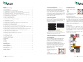
Survey & Installation Manual
Timber Windows & Doors
FSC SUPPLIER
SA-COC-0975 BER
Contents
1. Surveying & Measuring
Height Measurement
1. Survey & Measuring . . . . . . . . . . . . . . . . . . . . . . . . . . . . . . . . . . . . . . . . . . . . . . . . . .3
This survey and installation manual is intended as a
general guide to measuring and installing Bereco
products. By virtue of the wide variety of building types,
ages and construction methods, it cannot offer solutions
to cover all circumstances. The final responsibility for
accurate dimensions, correct specification and compliance
with all statutory regulations (including health and safety),
codes of practice, contract design management
requirements and all other best practice procedures rests
with the Approved Installer.
The height of the aperture
should be measured at three
points;
Left
Middle
Right
The smallest dimension should
be used to determine the
height (See Figure 1).
1.1 General Regulations
. . . . . . . . . . . . . . . . . . . . . . . . . . . . . . . . . . . . . . . . . . . . . . . . . . . .3
1.2 Measuring Windows in new-build situations . . . . . . . . . . . . . . . . . . . . . . . . . . . . . . . . . .3
1.2.1 Flat Windows (no reveal, with or without Cavity Closures) . . . . . . . . . . . . . . . . . . . . . .3
1.2.2 Manufacturing Size Flat Windows (no Reveal, with or without Cavity Closures) . . . . . .4
1.2.3 Flat Windows (with Reveal, with or without Cavity Closures) . . . . . . . . . . . . . . . . . . . .4
1.2.4 Manufacturing Size Flat Windows (with Reveal, with or without Cavity Closures)
. . . .5
1.2.5 Bay Windows in new-build situations . . . . . . . . . . . . . . . . . . . . . . . . . . . . . . . . . . . . . .5
Diagonal Measurement
1.2.6 How to measure Bay windows . . . . . . . . . . . . . . . . . . . . . . . . . . . . . . . . . . . . . . . . . . .5
1.2.7 Bereco Ltd Bay Ordering Form . . . . . . . . . . . . . . . . . . . . . . . . . . . . . . . . . . . . . . . . . . .6
1.3 Measuring Windows in refurbishment situations . . . . . . . . . . . . . . . . . . . . . . . . . . . . . . .6
1.3.1 Flat Windows (no reveal) . . . . . . . . . . . . . . . . . . . . . . . . . . . . . . . . . . . . . . . . . . . . . . . .6
1.3.2 Flat Windows (existing reveal) . . . . . . . . . . . . . . . . . . . . . . . . . . . . . . . . . . . . . . . . . . . .6
1.3.3 Manufacturing Size Flat Windows (either with or without existing reveal) . . . . . . . . . . .6
1.3.4 Bay windows in refurbishment situations . . . . . . . . . . . . . . . . . . . . . . . . . . . . . . . . . . . .6
1.4 Measuring Doors in new-build situations . . . . . . . . . . . . . . . . . . . . . . . . . . . . . . . . . . . . .7
1.4.1 Flush & French Doors (no reveal, with or without Cavity Closures) . . . . . . . . . . . . . . . . .7
1.4.2 Manufacturing Size Flush & French Doors (no reveal with or without Cavity Closures) .7
1.4.3 Flush & French Doors (Reveal, with or without Cavity Closures) . . . . . . . . . . . . . . . . . . .8
1.4.4 Manufacturing Size Flush & French Doors (Reveal with or without Cavity Closures) . . .8
1.5 Measuring and Manufacturing Sizes for Doors in refurbishment situations . . . . . . . . . . .8
1.5.1 Flush & French Doors (no existing reveal) . . . . . . . . . . . . . . . . . . . . . . . . . . . . . . . . . . . .8
1.1 General Regulations
If the diagonals differ, the window size should be reduced
accordingly so that when the new frame is offered up to
the aperture it can be installed square, normally with the
aid of packers in the appropriate places. If the diagonals
vary by more than 10mm, additional outer trims may be
required to conceal the gaps between the frame and
aperture. The customer should be advised of this and
agree to it prior to order confirmation.
Windows are vital elements of houses and dwellings and
therefore need to comply with various regulations in both
their stand-alone performance as well as in built-in
situations. The following regulations will give information
regarding these regulations:
Conservation of Fuel & Power
England & Wales
AD L1A & AD L1B
Scotland
Part J
Northern Ireland
Technical Booklet F
England & Wales
Scotland
Northern Ireland
Means of Escape from Fire
England & W ales
AD B
Scotland
Part M
Northern Ireland
Technical Booklet E
Glazing (Safety)
England & W ales
AD N
Scotland
Section 4
Northern Ireland
Technical Booklet V
Protection from Falling
England & Wales
AD K
Scotland
Section 4
Northern Ireland
Technical Booklet H
Ventilation
AD F
Section 3
Technical Booklet K
Cill Extensions
The distance from the face of the building to the front
face of the cill extension should be no less than 25mm.
The distance of the internal face of the frame should be
at least 30mm into the cavity to comply with Part L of
Building Regulations.
AD = Approved Document
Guidance on Building Regulations can be found on the following websites:
for England & Wales: Department for Communities & Local Government:
www.communities.gov.uk
for Scotland: Scottish Building & Standards Agency: www.sbsa.gov.uk
for Northern Ireland: Department for Finance & Personnel: www.communities.gov.uk
All Dimensions need to be taken in the place where the
windows will sit once installed.
1.5.2 Flush & French Doors (existing reveal) . . . . . . . . . . . . . . . . . . . . . . . . . . . . . . . . . . . . . .8
1.6 Measuring Special Doors and Doors in Special Situations . . . . . . . . . . . . . . . . . . . . . . . . .9
1.6.1 Sliding Patio Doors HS . . . . . . . . . . . . . . . . . . . . . . . . . . . . . . . . . . . . . . . . . . . . . . . . . .9
1.6.2 Tilt & Slide Doors PSK . . . . . . . . . . . . . . . . . . . . . . . . . . . . . . . . . . . . . . . . . . . . . . . . . .9
Figure 1
Windows and Doors are non-load-bearing elements and
structural support, like lintels are necessary.
Figure 2
1.2 Measuring Windows in new-build situations
1.6.3 Folding - Sliding Doors FS . . . . . . . . . . . . . . . . . . . . . . . . . . . . . . . . . . . . . . . . . . . . . . .9
2.1 Fixing . . . . . . . . . . . . . . . . . . . . . . . . . . . . . . . . . . . . . . . . . . . . . . . . . . . . . . . . . . . . . . . .9
2.2 Support . . . . . . . . . . . . . . . . . . . . . . . . . . . . . . . . . . . . . . . . . . . . . . . . . . . . . . . . . . . . .10
2.3 Sealing . . . . . . . . . . . . . . . . . . . . . . . . . . . . . . . . . . . . . . . . . . . . . . . . . . . . . . . . . . . . . .10
2.4 Coupling . . . . . . . . . . . . . . . . . . . . . . . . . . . . . . . . . . . . . . . . . . . . . . . . . . . . . . . . . . . .10
3. Final Inspection . . . . . . . . . . . . . . . . . . . . . . . . . . . . . . . . . . . . . . . . . . . . . . . . . . . . .11
4. Site Re-Glazing . . . . . . . . . . . . . . . . . . . . . . . . . . . . . . . . . . . . . . . . . . . . . . . . . . . . . .12
4.1Removing Timber Beads . . . . . . . . . . . . . . . . . . . . . . . . . . . . . . . . . . . . . . . . . . . . . . . . .12
1.2.1 Flat Windows
(no reveal, with or without Cavity Closures)
The way to measure flat windows is exactly the same,
regardless of the use of pre-formed Cavity Closures but
these Formers are required during construction and
therefore assure correct building. In this case, no
measurements of the final opening need to be taken.
Formers determine the structural opening size and therefore
the window size, which guarantees a perfect fit. Cavity
Closures can be made to agreed structural sizes. Bereco
simply deducts a tolerance to achieve a window size.
Overall Frame Size
2. Installation . . . . . . . . . . . . . . . . . . . . . . . . . . . . . . . . . . . . . . . . . . . . . . . . . . . . . . . . . .9
Structural Opening Size
1.6.4 Doors coupled to windows . . . . . . . . . . . . . . . . . . . . . . . . . . . . . . . . . . . . . . . . . . . . . .9
4.2 Removing Glass . . . . . . . . . . . . . . . . . . . . . . . . . . . . . . . . . . . . . . . . . . . . . . . . . . . . . . .12
4.3 Replacing Glass & Beads . . . . . . . . . . . . . . . . . . . . . . . . . . . . . . . . . . . . . . . . . . . . . . . . .12
Width Measurement
5. Health & Safety . . . . . . . . . . . . . . . . . . . . . . . . . . . . . . . . . . . . . . . . . . . . . . . . . . . . .12
The width of the aperture should
be measured at three points;
Top
Middle
Bottom
The smallest dimension should be
used to determine the width (See Figure 1).
Bereco Delivering the Difference
2
M in
30m m
Figure 1
3
Bereco Delivering the Difference
30
m
Note: Please always provide a template when shaped /
angled / arched windows are ordered.
Without Cavity Closures
When no Cavity Closures are used tolerances between
the structural opening size and the overall window size
need to be taken into account.
This is necessary to allow the window to be fixed to walls
and to insulate all window – wall connections.
Should the reveal used be more than 10mm bigger for
either jambs or heads than the dimensions shown above,
additional timber packers can be ordered to
accommodate for it.
Reveal Size
1.2.3 Flat Windows (with reveal, with or
without Cavity Closures)
Remember: Where the final wall finish is to be render, the
thickness needs to be included in the overall cover prior
to ordering (ie. the final window size will be smaller in
both width and height).
Worked example: Daylight sizes are 900mm wide x 1500mm
high, Sliding Sash window Cords & Weights, reveal size = 100mm
on jambs and 50mm on head
Window Sizes:
Width = 900mm + 2 x 95mm1 = 1090mm
(overall width of window)
Height = 1500mm + 41mm1 –10mm2 = 1531mm
(overall height of window)
Figure 7.1
Internal Structural Opening Width
Overall Frame Size (Width)
95
Window Daylight Width
Measuring bay windows is not as difficult as it may seem.
The most important rule in order to get the windows
right is continuity in measurement, where dimensions are
taken the same way throughout. The best ways to
measure bay windows are:
Along the external face of the internal brick / blockwork
Along the internal face of the external brick / blockwork
(favoured, see Figure 8)
Along the external face of the external brick / blockwork
To avoid errors and unnecessary questions it is important
to stick to either one of these options and not to mix
between them.
It is also necessary to know, which wall detail (Figure 6.2 /
7.2) is chosen and what size of cavity is used for the
building.
Be careful with this calculation that the reveal size is not
either the same size or smaller than the maximum cover –
there is still some tolerance (usually 5mm all-round) required
to allow for a tight but easy fit. In this case the maximum
cover should be reduced to suit the reveal depth.
Again, when Cavity Closures are used it is fairly
straightforward to determine window sizes, similar to
straight-through openings. Bereco will assist you in this
manner as best possible.
If in doubt of how to
measure bay windows
or for further technical
details please contact
the Bereco sales office
01709 838188.
1.2.5 Bay Windows in new-build situations
Bay windows whether square or angled require careful
consideration when planning building detail and
installation. The Building Regulations (Approved
Document L) require that the thermal performance
around openings achieve levels that some traditional
methods of bay window installation cannot meet.
In some situations a so-called ‘birds-mouth’ detail was
used to set the bay window into the corner of the
brickwork. Most of these details are unacceptable under
current Regulations as they usually create a ‘thermal
bridge’, which causes heat loss and therefore invalidates
achieved energy performance of the whole element.
In this manual we consider 2 different ways to overcome
this problem. However, there are various ways to avoid
thermal bridges but the most elegant ways are shown in
figures 5, 6, 7.
Front Bay Width
Overall Width of Bay Window
overall projection of Bay
Re
tu
rn
4
rn
tu
Re
y
Ba
Overall Width of Bay Window
overall projection of Bay
Front Bay Width
min
30mm
Figure 5.1
Ba
y
Front Bay Width
It is important to take some dimensions at various points
(for example the overall projection) in order to spot any
abnormalities.
Height dimensions need to be taken from the cill to the lintel
at various points similar to the measurement of flat windows.
Figure 5.2
Bereco Delivering the Difference
2
Figure 9 shows
dimensions that need
to be taken when bay
windows are ordered
(please use Bereco bay
window ordering form).
In this case all
dimensions are taken
along the inside face of
the external block /
brickwork.
Figure 9
It is not crucial to
measure diagonal dimensions 1 and 2 for square bay
windows, however it gives the opportunity to check if the
90 degrees angles are correct (they are if both diagonals
give the same dimension).
Reveal Size
Figure 4
1
on
ensi
l Dim
gona
Dia D
iago
nal
Dim
ensi
on
y
Ba
External Structural Opening Width (Daylight Size)
95
Figure 7.2
1.2.6 How to measure Bay windows
rn
tu
Re
The general rules for measuring windows where a reveal
has been formed are the same as for flat windows with
straight-through openings. That
means width and height
measurements should also be taken
in 3 places and diagonal dimensions
should be checked.
The difference is the place where
these dimensions are taken. To
determine the correct window size
it is very important to allow for the
right cover. In order to do that
structural sizes required are
daylight sizes, ie. dimensions
between the external brickwork as
shown on figure 3 and 4. In order
to achieve the correct window size
the correct reveal dimensions are
required (for example 100mm jambFigure 3
reveal / 50mm head reveal).
Figure 6.2
Figure 6.2
2 = 10mm tolerance used for cement bed at cill
Product
Max Cover Jamb Max Cover Head
Tilt & Turn
10mm
5mm
Lipped Casement
30mm
0mm
Flush Casement
35mm
0mm
Reversible
10mm
5mm
SS Spiral Balance
41mm
41mm
SS Cords & Weights
95mm
41mm
Note: Please always provide a template when shaped /
angled / arched windows are ordered.
Overall Frame Size
Width = daylight width + 2x jamb cover
Height = daylight height + head cover – tolerance on cill (usually
5/10mm)
1 = maximum cover for jambs and head
Table 1: Max Reveal Cover for Windows
The overall tolerances for flat windows should be 10mm
in both width and height (5mm all-round) to allow for
easy handling and fixing as well as a ‘tight fit’.
Further information can be found in British Standard BS
644.
Structural Opening Size (Daylight Size)
Figure 6.1
Retrun Bay
When Cavity Closures are used the actual Cavity Closure
determines the window size so no site measures are
required. Dimensions for the Closure are taken off plans.
A major advantage of using Cavity Closures is that a
perfect fit can be achieved (correct tolerances are allowed
for). Moreover, all windows can be ordered in advance. As
a result the building process will not be held up by delays.
Cavity Closures can be ordered by Bereco – please contact
the office for details.
Both dimensions of the external brickwork and the
required cover determine the final window sizes. The
general rule to calculate overall width and height is:
5
Ba
y
With Cavity Closures
1.2.4 Manufacturing Size Flat Windows (with
Reveal, with or without Cavity Closures)
Re
tu
rn
By the use of pre-formed Cavity Closures for the building
it is again straight forward to achieve perfectly fitting
windows since all openings are created with formers as
they determine window sizes.
Planned dimensions can be taken off drawings however, it
is very important to know the correct reveal size in order
to allow enough tolerance for both aesthetics and
functional reasons (Casement windows for example
wouldn’t open if tolerance was too little).
Table 1 shows the maximum coverage for different Bereco
window types.
30 min
m
m
1.2.3 continued
Retrun Bay
1.2.2 Manufacturing Size Flat Windows (no
reveal, with or without Cavity Closures)
Bereco Delivering the Difference
Figure 10
Similar to a survey of existing flat windows without reveal
it is important for existing windows with reveal to
measure both width and height at various places and all
dimensions again need to be wall-to-wall dimensions (ie.
all render needs to be removed).
It is also necessary to measure the existing reveal size at
both jambs and head. This is best possible with a metal
ruler or a screwdriver.
Detailed information regarding the cill detail / required cill
extension is necessary to assure full performance of all
new windows.
1.2.7 Bereco Ltd. Bay Ordering Form
Please always comment on:
• Where the dimensions have been taken from (internal /
external face of internal / external blockwork)
• What size of Cavity is chosen for the building
• Which wall detail is going to be used (see Figures 5 / 6 / 7)
• What cill is going to be used (eg. sloped brick cill / pre
cast concrete / stone cill)
• What external wall finish will be used
• What cill extension size is required
1.3.3 Manufacturing Size Flat Windows (either
with or without existing reveal)
Once the structural dimensions have been taken,
tolerances need to be added in order to allow a perfect fit.
In this circumstance the same rules are valid as those for
windows in a new-build situation. Please allow for
sufficient tolerances and beware of maximum cover for
existing reveals (see table 1).
Note: For bay windows we recommend forwarding
structural opening sizes instead of final window sizes to
accommodate for additional requirements. The technical
team at Bereco will assist you in this.
1.3 Measuring Windows in refurbishment situations
1.3.4 Bay windows in refurbishment situations
The steps to measure bay windows for refurbishment
situations are the same as for flat windows, however it
might be a bit more difficult to get to the correct wall-towall dimensions. Therefore render / plaster needs to be
removed at various places in order to take the dimensions
correctly.
Furthermore it is necessary to know in what way the bay
window is connected to the walls and what the wall is
made of (ie. size of cavity, bricks and cill details).
1.3.1 Flat Windows (no existing reveal)
Replacement windows are usually measured and ordered
before the existing windows are taken out and extra care
is required during site-measure.
Width Measurement
The width of the aperture should be measured at three
points;
Top
Middle
Bottom
The smallest dimension should be used to determine the
width (See Figure 1).
Note: Please always provide structural opening sizes
rather than calculating final window sizes for bay
windows in refurbishment situations. It is also always
helpful for our technical team if photographs can be
supplied for any difficult situation.
Height Measurement
Doors of any kind, like windows, are not designed to be
load bearing. Please contact your structural engineer for
advice, especially when large door sets like Folding-Sliding
Doors or Sliding Patio Doors are considered.
General Regulations (Building Regulations) are valid for
both windows and doors. Please refer to the Building
Regulations mentioned earlier in this manual.
1.4.1 Entrance & French Doors (no reveal, with
or without use of Cavity Closure)
If Cavity Closures are used (they can be ordered directly
through Bereco) then there is no survey required since all
sizes are determined by the Closures.
If no Cavity Closures are used all dimensions should be
taken like window sizes.
Bereco Delivering the Difference
Table 2: Maximum floor cover for door
thresholds (please see Brochure for details)
Width Measurement
The width of the aperture should be measured at three
points;
Top
Middle
Bottom
The smallest dimension should be used to determine the
width (See Figure 1).
Standard Site-Coupling Mobility
(Option 1) (Option 2) (Option 3)
Flush Door open in
30mm
30mm
0mm
Flush Door open out
35mm
35mm
0mm
French Door open in
30mm
30mm
0mm
French Door open out 35mm
35mm
0mm
Sliding Door HS
40mm
N/A
N/A
Tilt & Slide Door PSK
0mm
N/A
N/A
Folding Sliding Door FS See figure 14
Height Measurement
The height of the aperture should be measured at three
points;
Left
Middle
Right
The smallest dimension should be used to determine the
height (See Figure 1).
1.4.2 Manufacturing Size Entrance & French Doors
(no reveal, with or without Cavity Closures)
As with the windows, fitting tolerances need to be
deducted when structural openings are measured in order
to get to overall frame sizes. The general tolerances are
5mm all-round or 10mm in both width and height.
If the threshold is to be sunk into the floor in order to
reduce the step this
dimension needs to be
added once fitting
tolerances have been
deducted.
Figure 11 shows that the width measurement is taken
between structural walls and it shows that it is very
important to consider the final wall finish and its
thickness in order to allow the door to open properly.
Usually the same cover is used on Jambs and Head of the
doorframe.
5m m
to le ra n c e
S in g le F lu s h D o o r O p e n In
S in g le F lu s h D o o r O p e n O u t
19m m S kirting board
19m m Skirting board
12.5m m P lasterboard
12.5m m Plasterboard
5m m dot/dab
(norm ally 15m m )
5m m dot/dab
(norm ally 15m m )
Internal Blockw ork
Internal Blockw ork
4
The height of the aperture should be measured at three
points;
Left
Middle
Right
The smallest dimension should be used to determine the
height (See Figure 1).
There are various types of thresholds available, depending
on access and building requirements. For some of the
thresholds (please refer to Bereco Brochure) it is possible
to sink them into the floor to reduce the final step. In
order to do this screed needs to be cut (or space needs to
be allocated beforehand) and the overall frame height
needs to be increased by the size that the threshold is
sunk in.
Door thresholds must not be sunk in too much –
especially with open in doors there is a danger that doors
won’t open once tiling / timber flooring or carpets are
finished.
Table 2 shows the maximum recommended size a door
threshold should be sunk into the floor.
Figure 12 shows how
door thresholds can be
sunk into the floor (in this
case 30mm). It is always
important to know about
the final wall finish
(render / brick / cladding)
in order to avoid problems
(particularly with open out
doors). Our technical team
can assist you if you have
any question.
66
5m m tolerance
5m m tolerance
E xternal B lockw ork
External Blockw ork
s/o w idth m easured to w all
s/o w idth m easured to w all
Figure 11
6
7
5m m
to le ra n c e
smallest structural height = 2100mm
1.3.2 Flat Windows (existing reveal)
Height measurements always need to be taken from the
bottom of the lintel to the top of the Finished Floor, at 3
different places as indicated above.
1.4 Measuring Doors in new-build situations
overall frame height = 2120mm
It is important that the external wall-to-wall dimensions
are taken and not the old frame sizes. In order to do so,
render and sealing (mastic) need to be removed prior to
the measure.
It is also necessary to inform Bereco about the existing cill
detail and required cill extensions.
Please always check for reveals that might eventually exist.
Figure 12
3 0 m m s u n k in to flo o r
Bereco Delivering the Difference
Weather Board
1.4.3 Flush & French Doors (Reveal, with or
without use of Cavity Closure
Measuring doors with a reveal wall detail is similar to
measuring windows with a reveal; the same information
is required. That means the overall dimension from brick
to brick is required as well as the size of reveal.
When Cavity Closures are used there is again no measure
required since the Closure acts like a Former and window
sizes are determined with the Closure. The reveal sizes
and the Cavity width are necessary to order Cavity
Closures.
It is very important (regardless of the use of Cavity
Closures) that the maximum cover for doorframes is not
exceeded. Table 3 gives advice on the maximum cover for
doors. That is the overall cover (including reveal and final
wall finish).
Flush Flush French French Sliding Tilt & Folding
Door Door Door Door Patio Slide Sliding
open open open open Doors Doors Doors
in
out
in
out
(HS) (PSK)
(FS)
Max
0mm
Jambs 45mm 20mm 60mm (packer 50mm 60mm 60mm
Cover
rqd)
Bereco Delivering the Difference
Newbuild Situation
All Bereco windows and doorsets should be fitted into
preformed openings, which are at least 10mm larger
(5mm all round) than the overall frame size. In the case of
new buildings or extensions, frames should not be built in
as the work proceeds.
Frames should be installed plumb and square using metal
fixings or perimeter battens and Figure 16 shows typical
fixing centres. Please use spirit levels to assure windows
and doorsets are installed plumb and square.
A minimum of two fixing points per side (depending on
height) should be used. These should be positioned at
between 100mm & 200mm in from each corner.
Additional fixings will depend on the size of the frame as
follows: Frame height up to 1000mm
= 2 per side
1000mm to 1600mm
= 3 per side
1601mm to 2100mm
= 4 per side
Over & above maintain 450mm centres.
Where the frame width exceeds 1800mm or is formed by
two or more coupled units, fixings should be provided at
the head and cill.
1.6.3 Folding – Sliding Doors FS
PSK Tilt & Slide Doors are easy to measure and should be
handled the same way like any other door. That means it
is necessary to think about reveals and final wall finishes.
There are 2 threshold options, which both can be sunk
into the floor (see tables 2 & 3 and figure 14). As these
doors fold to the inside it is also necessary to think about
Aluminium Mobility Threshold
not availible with all models
(see brochure for details)
Standard Timber Threshold
availible with all models
sunk into Screed
by 21mm leaving
18mm step
sunk into Screed
by 40mm leaving
62mm step
18
Top of 20mm
Flooring
FFL
Top of 20mm
Flooring
FFL
11
x
68
116
Figure 14
150mm Approx.
450mm Approx.
Centres
450mm Approx.
Centres
1.6.4 Doors coupled to windows
When doors are coupled to windows (for example
Entrance Doors) the overall aperture needs to be
measured as one. The procedures to measure are exactly
the same as described before, however, a few more
8
Figure 15
C1
2.1 Fixing
1 reduced to 15mm when vent is provided
Should the required cover exceed the recommendations
there is a chance to order additional timber packer to
allow for a tight and correct fit.
A2
This survey and installation manual is intended as a
general guide to measuring and installing Bereco
products. By virtue of the wide variety of building types,
ages and construction methods, it cannot offer solutions
to cover all circumstances. The final responsibility for
accurate dimensions, correct specification and compliance
with all statutory regulations (including health and safety),
codes of practice, contract design management
requirements and all other best practice procedures rests
with the Approved Installer.
the internal plasterboards / skirting boards and tolerances
towards walls. Please contact Bereco for assistance.
Due to their size it is recommended to seek assistance
during the measuring process in order to avoid mistakes.
Max
0mm
0mm
Head 45mm (packer 60mm (packer 50mm1 60mm 72mm
Cover
rqd)
rqd)
W2
E2
PSK Tilt & Slide Doors are easy to measure and should be
handled the same way like any other door. That means it
is necessary to think about reveals and final wall finishes.
It is not possible to sink the threshold of these doors into
finished floor (see tables 2 & 3).
Due to their size it is recommended to seek assistance
during the measuring process in order to avoid mistakes.
2. Installation
D1
F2
1.6.2 Tilt & Slide Doors PSK
The steps to measure doors for refurbishment situations
are exactly the same as for replacement windows. That
means both width and height need to be measured in
different places once plaster has been removed in order
to provide wall-to-wall sizes. Do not measure the existing
frame.
It is unlikely that thresholds will be sunk into the floor
when doors are replaced so height dimensions should be
taken between lintel and finished floor (that is below tiles
/ carpet / timber flooring). However, if sinking in is still
required please follow the steps outlined above.
Once these dimensions have been taken fitting tolerances
need to be deducted. Be careful that the final wall finish
does not exceed the recommended dimensions for frame
covers (see table 3).
D1
C2
A1
B2
1.5.1 Flush & French Doors (no existing reveal)
F1
1.5 Measuring and Manufacturing Sizes for
Doors in refurbishment situations
The measurement of doors with existing reveals is as
simple as measuring doors without. The required
dimensions are again to be taken between the external
brickwork of both sides. It is important to know reveal
sizes, which can be measured best with a metal ruler. In
order to measure the correct hard opening sizes it is
necessary to remove existing render prior to the measure.
The overall door sizes can be easily calculated by adding
the required reveal cover, which should not exceed
dimensions shown in table 3. Please also accommodate
for sufficient fitting tolerance (5mm all-round) when door
dimensions are calculated.
Table 3: Maximum Reveal Cover
W1
HS Sliding Patio Doors are easy to measure and should be
handled as any other door. That means it is necessary to
think about reveals / final wall finishes and whether or
not thresholds are going to be sunk into the finished floor
(see tables 2 & 3).
Due to their size, however, it is recommended to seek
assistance during the measuring process in order to avoid
mistakes.
1.5.2 Flush & French Doors (existing reveal)
Lintel
D2
21
Figure 13
Lintel
1.6.1 Sliding Patio Doors HS
59
Internal Blockwork
dimensions are necessary in order to achieve a perfect fit.
Figure 15 shows which dimensions should be taken
during measure. In this case it is advisable to provide
structural
opening sizes
rather than
calculating final
window / door
sizes.
B1
Measuring doors in new-build situations and when a
reveal is formed is as straightforward as with windows in
the same situation. That means that the external brick-tobrick dimensions need to be taken and reveal sizes and
cover needs to be considered (see worked example page
5 and table 3). Please also consider by how much – if at
all – thresholds are going to be sunk into the floor.
62
19mm Skirting board
12.5mm Plasterboard
5mm dot/dab
(normally 15mm)
1.6 Measuring Special Doors and Doors in
Special Situations
E1
1.4.4 Manufacturing Size Flush & French Doors
(Reveal, with or without Cavity Closures)
40
Figure 13 shows why it is important to inform Bereco
about the final wall finish.
Additional fixings to windows
1800mm wide and above.
450mm Approx.
Centres
150mm Approx.
Figure 16
9
Bereco Delivering the Difference
Refurbishment Situation
Fixing will normally be through the frame; although fixing
lugs, which facilitate fixing from inside the building can
also be used.
Purpose made nylon fixings are available. These utilise the
same diameter hole through the frame and substrate, and
are normally supplied together
Wall
Window
with screws.
Alternative fixings include a
proprietary screw device, which
enables the window position to
be adjusted on the fixing itself
(See figure 17).
Figure 17
Fixings should not be overtightened and surrounding
brickwork should abut the frame
Gap adjusted by turning
thread in window
only lightly so that no frame
distortion can occur.
Before final fixing, check that opening sashes have equal
clearance on both sides. Mullions of multi-light windows
MUST be supported to avoid sagging.
2.3 Sealing
3. Final Inspection
To prevent air infiltration between the window/door and
adjacent wall the gap between the window and wall
should be sealed. Polythene backed sealing strips can be
fitted prior to installation or alternatively an expanding
foam seal or mineral wool can be fitted after installation
has been completed.
When using gap-filling
foams avoid injecting
excessive amounts as this
may deflect the jambs and
FL
induce vertical bow.
Finally, a silicone or
polysulphide based sealant
(Approved to BS 5889)
should then be applied
(see Figure 19).
Following completion, a final inspection should be carried out to ensure that the installation is of the highest standard.
We recommend that there should be a formal procedure for checking the work, using a checklist similar to the one
shown below. We also recommend that these checks should be carried out in the presence of the customer, who
should be familiarised with the operation, and Bereco operating and maintenance instructions should be left with the
customer.
Area to be checked
OK
Yes/No
Visual Appearance
1
Windows installed plumb, square and vertical.
2
Exposed faces including beads free from surface damage.
3
Window and frame clean and all protective film removed.
4
Check for damage around surrounding aperture.
5
Check all internal trims are installed correctly.
6
Check the site is clean and all debris is removed.
1
Glazing as specified.
2
No cracks or scratches on glass, or signs of unit failure.
3
Obscure glass is oriented the correct way.
Figure 19
2.4 Coupling
When windows are coupled to doors (see figure 15) they
need to be coupled before installation (see figure 20).
Bereco provides jointing slips and cover facings.
Additional coupling material (screws, screw covers etc) is
supplied by the approved installer.
Jointing slips need to be glue-fixed in relevant grooves
and the overall construction has to be pre-drilled and
screw-fixed at various places as shown in figure 20.
2.2 Support
Packing pieces should be located at all fixing points. If
additional packing pieces are required to raise the position
of the frame in the aperture or to compensate for the
base of an aperture that is not level, all mullions must be
supported, as shown in figure 16 & 18
If additional packing pieces are required to raise the
position of the frame in the aperture or to compensate
for the base of an aperture that is not level, all mullions
must be supported, as shown in Figure 16 & 18.
Particular care is necessary when providing packing to
vertical sliding windows, where even minor distortions
can prevent the movement of the sashes or introduce
excessive clearance. When fitting packing, the correct
operation of sashes should be checked prior to fixing and
a mortar bed can be used to provide continuous support
at cill level.
Glazing
Operation
internal & external
cover facings supplied
loose by Bereco
Jointing Slips
provided loose
Figure 20
Sight Lines
Figure 18
1
All opening sashes open and close correctly
2
No air gaps between seals and frames.
3
No scraping or rubbing between Espagnolette and keepers.
4
When doors slam, no bounce, or outer frame movement
5
All operation gear correctly lubricated.
6
All hardware attached with correct number of fixings.
1
Visually correct.
2
Adjacent vents aligned.
1
Sealant to be continuous around frame run.
2
No excess sealant to be present on frame faces.
Pre-Drill and screw
Sealing
Additional support
under mullions
Additional
support
be provided
MUST
under mullions
MUST
when
packing
be provided.
pieces are used
150mm Max
Inspection
Bay Windows
1
Ensure no settlement of structure when temporary supports removed.
2
Check that flashings and DPC have not been disturbed or damaged.
150mm Max
Bereco Delivering the Difference
10
11
Bereco Delivering the Difference
4. Site Re-Glazing
Silicone the edge between glass and timber on both the
inside and outside with correct coloured silicone (BS 5889
approved). Spray lubricated water on the silicone and use
a PVC-scraper to smoothen surface as shown in figure 24.
4.1 Removing Timber Beads
Where de-glazing is necessary, cut the silicone along the
glass-timber edge with a utility knife and remove the
silicone (figure 21).
Remove all timber beads, starting with the longest ones
by tapping the bead towards the centre of the pane using
a plastic glazing chisel (see Figure 22). This should
separate the bead from the sash or frame.
The chisel can then be used to prise it off completely.
Repeat this process for the remainder of the beads.
Remove any nails from the glazing rebate.
Nails that are left in the glazing bead should be pulled
through the back of the bead with a pair of pincers to
avoid break out through the face. Remove any silicone
from the beads.
step 1: silicone
(BS 5889
approved)
1
Figure 24
2
step 2: spray with lubricated
water and smoothen surface
with scraper
For further glazing information please refer to BS 8000
Part 7 1990, BS6262 Glazing in Buildings & NHBC
Standards Charter 6.7 January 1999 edition as of January
2000
Utility knife
Security Tape
cut
security
tape
Cut silicone on both
inside and outside
use glazing
chisel towards
the centre of
the pane with a
hammer
5. Health & Safety
Bereco windows and doors come packed in a loose
polythene bag and securely strapped on wooden pallets.
Mechanical Offloading facilities are provided when
elements are delivered to site using a Moffet-Forklift
vehicle.
The weight of each item is shown on the sales
confirmation and there are health and safety instructions
attached to each element.
Figure 22
Figure 21
4.2 Removing Glass
Before removing the sealed unit, the double-sided security
tape must be cut from the outside and all glazing blocks
need to be removed using the glazing chisel as lever. The
glass should then be removed from the inside (from
outside for Reversible windows)
It is the responsibility of the approved installer to make
him/her self aware of any Health & Safety and
Construction Design and Management Regulations that
may apply to the work he/she is undertaking.
4.3 Replacing Glass & Beads
Remove the remainder of the silicone and the security
tape from the glazing upstand. Where security tape has
been damaged replace it with new tape.
Place the glass into the glazing check, ensuring equal
spacing all around. Correct spacing of the glass blocks is
shown in Figure 23. The centre of the glazing block
should be approximately 100mm from the corner.
Beads should be replaced fixing the smallest ones first
then the longer ones, ensuring compression on the
glazing tape. Nails should be punched and filled with
appropriate coloured filler and the face of the bead
should be repainted/stained.
Unit 5
Aspen Court
Centurion Business Park
Bessemer Way
Rotherham
S60 1FB
Figure 23
Bereco Delivering the Difference
12
Tel: 01709 838188
Fax: 01709 838330
Email: [email protected]