1
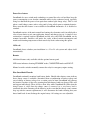
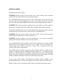
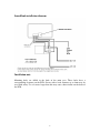
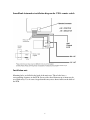
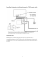
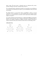
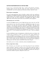
SmartBank/SmartBank Automotive owners/installation manual
General Description
SmartBank and SmartBank Automotive are auto-battery combine controllers that monitor
two battery banks and by making accurate measurements decide when to parallel them to
allow simultaneous charging and when to separate them to prevent cross-discharging.
The two units (SmartBank and SmartBank Automotive) are identical in features,
functions and physical form. The only differences are the options of the remote
panel/switch for each unit and the power saving feature which is not incorporated in the
Automotive version.
Unlike conventional split charge systems using diodes or relays SmartBank is not
affected by where the charge is coming from, nor does it have to be separately controlled
by alternator signals, manual switches etc. There is nothing for you to forget. Neither
does it suffer from the voltage drop problems of split charge diodes.
SmartBank automatically controls charging of 2 battery banks no matter which battery
bank is being charged. Whether it is an alternator, solar panel, wind generator or AC
powered charger SmartBank will take care of it automatically. You make sure your
charge source is connected to one battery bank, SmartBank will take care of the other
one, totally automatically. No more flat engine batteries because you forgot to switch the
battery selector over. No more uncharged house bank.
Not only is SmartBank better than a standard split charge relay or diode set up but it's
actually simpler and quicker to install. No modifications are required to the existing
installation. Only additional cabling is required thus ensuring warranties are not affected.
Remote Panel
An optional remote panel is available which connects to SmartBank simply by plugging
in an RJ11 type cable (supplied with the remote).
Alternatively SmartBank Automotive can be supplied with a dash mounted switch which
can be used for emergency battery paralleling to assist engine starting. Integral to this
switch is an LED which illuminates to show “connected” status.
Power Consumption
SmartBank has been designed and built using ultra low power semi-conductors and ultra
low power design techniques which results in a standby current that is so low, no
ON/OFF switch is required. Therefore you can never forget to switch SmartBank on
because you never need to switch it off. Standby power consumption is less than 0.2 Ah
per week.
1
Power Save feature
SmartBank also uses switch mode technology to control the relay coil and thus keep the
power consumption to an absolute minimum whilst in the connected mode (typically
using less than half the power of an equivalent standard split charge relay). This is vital
when a small charge source such a solar panel is being relied upon to maintain batteries.
Please note that this feature is not available in SmartBank Automotive. It is disabled as
standard.
SmartBank consists of the main control box housing the electronics and is installed with a
relay of your choice to suit your application, battery and charger size etc. A simple 5 wire
connection is required between SmartBank and the relay and GND. SmartBank can be
mounted anywhere. Installers will notice the vastly reduced current consumption and
much cooler running temperature of their usual relay choice when using this option.
12/24 volt
SmartBank detects whether your installation is a 12 or 24 volt system and adjusts itself
automatically.
Remote
Additional features only available with the optional remote panel
LED status indicators showing STANDBY mode, CONNECTED mode and FAULT.
Manual override switch to manually connect the relay for emergency engine starting.
How SmartBank II works
SmartBank continually monitors both battery banks. Should either battery status indicate
that a charge source is available (determined from a combination of battery voltage and
rate of change of battery voltage over a certain period of time) SmartBank will connect
the batteries together via the relay ensuring that both battery banks are charged. This will
not happen immediately. There will be a short delay while SmartBank II verifies that the
charge source is valid. Once the charge source is removed (or a very heavy load is
connected that risks flattening all the batteries in the event that the charge source cannot
keep up with the current requirements) it will disconnect the banks ensuring that your
house bank loads do not discharge the engine battery. All settings are user adjustable.
2
INSTALLATION
Installation could not be simpler.
WARNING Incorrect wiring of this unit may cause serious damage to the electronic
circuit and/or relay that will not be covered by the warranty.
It is recommended that the relay be sited as close to the batteries as possible. Not only
does this make the cable installation easier but it also reduces the losses that would
otherwise occur when running high battery charge currents through long battery cables.
WARNING The usual precautions regarding relays in proximity to possibly explosive
battery gasses should be taken. If in doubt consult a qualified marine/auto electrician.
As all control and indication is by way of the optional remote panel, the siting of the main
control unit can be made purely on a “safety and ease of installation basis”.
WARNING This unit contains sensitive electronic circuitry and the usual precautions
should be taken regarding water, dirt and oil ingress etc.
WARNING. Incorrect wiring to any of the terminals may cause serious, irrepairable
damage to the unit that will not be covered by the warranty.
It is recommended that 1mm2 cabling be used for the connections to the main terminal
block. If any of the connections need to be over 3 metres for any reason then it is
recommended that all cables be increased to 2mm2. This is purely to increase the
accuracy of the voltage measurements.
The cabling from the batteries to the main relay terminals cannot be specified in this
manual as it depends upon the installation and cable lengths etc. As a rough guide you
should use cable that will have a maximum voltage drop of 0.1 volts at the maximum
charge rate in your installation. Obviously this depends upon the cable length. If in doubt
consult a qualified marine/auto electrician or cable voltage drop chart.
In any event a cable capable of handling the maximum charge capability of the
installation MUST be used. Your cable supplier will be able to advise you on this point.
Failure to adhere to these instructions could result in overheating of the battery cables.
3
SmartBank installation diagram
Installation note
Mounting holes are drilled in the back of the main case. These holes have a
corresponding clearance on the PCB. Screws with a head diameter up to 8mm may be
used with safety. Use of screws larger than this may cause short circuits on the back of
the PCB.
4
SmartBank Automotive installation diagram for V2DA remote switch
Installation note
Mounting holes are drilled in the back of the main case. These holes have a
corresponding clearance on the PCB. Screws with a head diameter up to 8mm may be
used with safety. Use of screws larger than this may cause short circuits on the back of
the PCB.
5
SmartBank Automotive installation diagram for VXH2 remote switch
Installation note
Mounting holes are drilled in the back of the main case. These holes have a
corresponding clearance on the PCB. Screws with a head diameter up to 8mm may be
used with safety. Use of screws larger than this may cause short circuits on the back of
the PCB.
6
SET UP PROCEDURE
Decide on your voltage set points. If you are unsure of these refer to the Battery Types
section for standard set up guidelines. Professional installers may have their own
preferred settings depending upon the installation. Simply set the adjustments to the
required set points as shown in the calibration chart at the end of this manual.
Connect and Disconnect adjustments
There are three adjustments in SmartBank labelled “Connect”, “Disconn” (disonnect) and
“Hold”. “Connect” and “Disconn” correspondingly adjust the nominal voltages at which
SmartBank will connect and disconnect the battery banks. Basically when the battery
voltage (on either battery) rises to the connect voltage SmartBank will connect the
batteries together. Conversely when the overall battery voltage falls to the disconnect
voltage SmartBank will disconnect the battery banks. The reality is not quite this simple
in that the actual voltages are dynamically altered by SmartBank depending upon how
fast the battery voltage rises or falls. In addition to this there are delays before connecting
or disconnecting which again are dynamically altered by SmartBank depending upon how
fast the battery voltage rises or falls. This drastically improves the performance of
SmartBank over a primitive voltage controlled relay. For this reason it may at times
appear that SmartBank has disconnected or connected when it should not have done so if
the comparison is made to a simple battery voltage measurement. This is not the case. If
measurements are made to actually check whether or not true charging is taking place it
will be found that SmartBank is indeed connecting and disconnecting at the correct times.
A consequence of the dynamically modified voltage set points and delays is that the
actual “Connect” and “Disconnect” voltage set points are not actually as critical as it may
at first appear.
“Hold” adjustment
The “Hold” function is somewhat more involved. In an installation where the charge
source (say an alternator) is connected to the engine battery, and the house (domestic)
bank is deeply discharged, it may be the case that upon connection of the two battery
banks, the deeply discharged house bank will drop the overall battery voltage below the
"disconn” level. This of course will force SmartBank to disconnect the two battery banks.
SmartBank will then detect that the voltage on the engine battery has risen (indicating a
valid charge source) and reconnect the battery banks. The house bank may then drop the
voltage below the “Disconn” level again resulting SmartBank cycling between “Connect”
and “Disconn”. This cycling problem could continue for some considerable time until the
charge status of the house bank was sufficiently high to enable the alternator to keep the
overall voltage above the “Disconn” level.
The “Hold” function introduces a time delay immediately following “Connect” during
which SmartBank will not and cannot disconnect the relay no matter what happens to the
7
battery voltage. This time period is adjustable from zero (adjustment fully counterclockwise) through to 90 seconds (adjustment fully clockwise).
It is recommended that this adjustment be disabled if at all possible in your installation or
at least turned to the minimum period required to prevent SmartBank cycling at the initial
start of charge.
The “Hold” function is an extra feature added to SmartBank to enable it to operate
satisfactorily in poor installations. In a good installation where the batteries, battery
chargers etc are correctly sized to each other it will be found that the “Hold” function
simply is not required.
If, even after adjustment of the hold function it is found that SmartBank still disconnects
then this is because the charge source is simply too small for the overall battery bank size.
In this case no amount of adjusting or fiddling will achieve anything. The charger is
simply too small. The only course of action is to increase the size of the charge source.
Calibration Chart
8
BATTERY TYPES
These are typical figures required for various battery types assuming that the correct
battery charger is being used for the batteries. Clearly if the wrong battery charger is
being used (ie charging at an incorrect voltage for the selected battery type) then these
voltages will possibly need to be adjusted. If in doubt consult a qualified marine/auto
electrician or contact your dealer.
Wet cell batteries.
Connect voltage
Disconnect voltage
13.2v (26.4 on 24 volt systems)
12.8v (25.6 on 24 volt systems)
Gel cell batteries
Connect voltage
Disconnect voltage
13.4v (26.8 on 24 volt systems)
12.8v (25.6 on 24 volt systems)
AGM batteries
Connect voltage
Disconnect voltage
13.4v (28.8 on 24 volt systems)
12.8v (25.6 on 24 volt systems)
SPECIFICATIONS
Connect voltage range
Disconnect voltage
Hold time
Standby current draw
13.0 to 13.6 volts (26.0 to 27.2 volts on 24 volt systems)
12.6 to 13.3 volts (25.2 to 26.6 volts on 24 volt systems)
0 to 90 seconds
< 0.001 amp (< 0.02 watts) with remote
< 0.0004 amp (< 0.005 watts) no remote
Connected current draw cannot be specified for SmartBank as it depends almost entirely
upon the relay used but will typically be between 25 to 50% of the usual coil current
consumption for the relay chosen. SmartBank never uses more than 0.001 amps for it’s
own purposes while in standby or 0.008 amps maximum in any other mode.
Specifications are subject to change without prior notification.
9
TROUBLE SHOOTING
Symptom
Possible problem
Green LED lights up solid
but the relay does not energise
Faulty connections between C1 or C2 terminals
on the connector block and the relay coil.
Faulty relay.
Red LED is on permanently
SmartBank has successfully detected a CONNECT
voltage but the DISCONNECT voltage is set higher
than the CONNECT voltage. Run through the set up
procedure.
Charge source is switched
on, the unit connects then
disconnects almost immediately
The charge source is connected to the smaller
battery bank and the larger bank is deeply
discharged. This can cause the overall voltage to
fall below the disconnect voltage when the
banks are connected together. Either move the
charge source to the larger battery bank or lower the
disconnect voltage. Alternatively read the section on
the “Hold” function then adjust accordingly.
DISCONNECT voltage and CONNECT voltage are
set too close together.
The unit simply will not connect.
Green LED flashing.
Disconnect voltage is set higher than the connect
Voltage (RED LED will be lit). Refer to setting up
procedure.
Charge source is set lower than CONNECT
voltage. Either increase the charge voltage or
decrease the CONNECT voltage.
No charge source available or faulty charger.
10
NOTES FOR PROFESSIONAL INSTALLERS
If you are not a professional installer who is “au-fait” with electronics and battery
charging regimes do not read this section! No advice will be given and no
correspondence entered into regarding any information contained within this section.
Reduced power consumption
In a power critical application it may be desirable to reduce even the very small power
consumption of SmartBank by installing an on/off switch. This can be achieved by fitting
a SPST switch in series with R33 on the PCB. This will kill all power to the control
circuitry and reduce the current consumption of SmartBank from 700uA to around
100uA. This switch could be replaced with a relay controlled by other equipment.
Defeating the power save feature
At the time SmartBank connects it send a 350mS full power pulse to the relay coil. This
ensures that the relay closes fully and quickly. SmartBank then reduces the power
delivered to the relay coil by pulsed switch mode techniques. This has several
advantages:- A) It drastically reduces the “connected” current draw of SmartBank. B) It
vastly increases the operating life of the relay due to reduced coil dissipation (most relay
failures are due to the coil failing not the contacts). C) It enables the use of relays which
are not continuously rated to be utilised in continuous duty. D) It enables a 12 volt relay
to be used in a 24 volt installation (provided that 12 volt relay is rated for continuous
duty).
In some installations it may be advantageous to defeat the power save feature. One
example being an installation in which it is desired that some external equipment can
override SmartBank and disconnect or connect the relay in an AND/OR type scenario.
Disconnecting the feed from SmartBank to the relay coil will disconnect the relay ok but
will not always ensure it can be reconnected due to the relay requiring the full power
pulse to close correctly. For this reason the power save feature can be disabled by
soldering across the solder contacts on the PCB as shown in the diagram.
Note that the power save feature is disabled by default in SmartBank Automotive.
Battery compartment venting
Wet cell batteries give off explosive gases when being charged. In many installations
natural ventilation is sufficient to vent these gases to the outside world but in others it
may be necessary to force vent these using a fan. SmartBank is ideal for this additional
use by simply using another relay energised by SmartBank to control the fan. Obviously a
fan and relay suitable for explosive atmospheres must be used.
11
Additional relays
SmartBank can safely provide power to relays with a total normal coil current
consumption of 3 amps (note that this will not be the actual current draw due to the power
save feature), so additional relays can easily be added to parallel, say, a bow thruster or
windlass battery. If there is any doubt as to the total coil current consumption then use a
small relay energised by SmartBank to control the coil current to the larger relays.
Component identification
[031215]
12