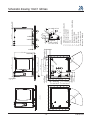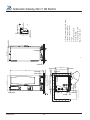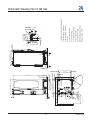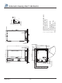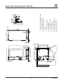
1
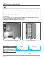
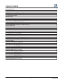
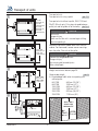
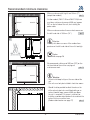
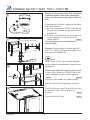
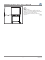
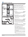
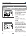
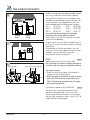
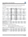
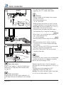
Original
Installation Manual
Safety instructions
Explanations of the icon's
Danger!
Immediate dangerous situation,
that can endanger severe injury
or death
Warning!
Possibly dangerous situation, that
possibly can endanger severe
injury or death.
Caution!
Possibly dangerous situation, that
can endanger minor injury.
Corrosive substances
Fire hazard!
Danger of burning!
Attention: Inobservance can
cause material damages.
Tips and tricks for installation
V-09 05/2014
-2-
Danger!
High voltage.
Caution danger of life
Inobservance can endanger
severe injury or death.
Safety instructions
WARNING
Wrong installation, service, maintenance or cleaning as well as unauthorized changes on the unit can cause
damages, injuries or even death. Read the installation manual carefully before installing the unit.
This unit may only be used for preparing food in commercial kitchens. Every other usage is against definition
and therefore dangerous.
WARNING
Only gas units
Waste gases!
- If the unit is installed underneath an extraction hood, it must be made sure that the hood is switched on
during operation of the unit
Fire hazard!
- If the gas unit is connected to a chimney, it must be made sure that the exhaust line will be cleaned on a
regular basis subject to local regulations (For this purpose also contact the installer)
- Don't put any material on the exhaust pipes of the unit
- The area underneath the unit may not be blocked or closed by any material
- The unit may only be operated in a calm environment
DANGER
Danger of explosion
Safety measures in case of smell of gas:
- Immediately close the gas supply.
- Don't touch any electrical switching element
- ventilation of the room.
- Avoid open flame or sparks
- Use an external telephone and inform your local gas authority (in case the local gas authority can not be
reached inform the operation centre of the fire brigade).
-3-
V-09 05/2014
Dear customer
The warranty excludes glass damage, light bulbs and sealing material as well as damage caused by improper
use, installation, maintenance, repair by untrained/unqualified personnel and scaling of components
We reserve the right to make technical changes in the interest of progress!
© 2011 Rational Technical Services. All rights reserved. Please note that any technical information concerning Rational products must NOT be forwarded to any third party.
Quote in the event of a query:
Dealer
Appliance model:
Appliance no.:
______________________________________
Installer
Set to gas type:
______________________________________
Your appliance was checked by:
Safety stickers „Max. rack height for containers with liquid“ are in the Starter Kit.
After Installation of the unit, this sticker has
to be fixed to the unit in a height of 1600
mm (see examples)
1600 (63")
1600 (63")
______________________________________
WARNING
Risk of scalding!
To avoid scalding, do not use loaded containers with liquids or cooking goods which becomes fluid by heating
in higher levels than those which can easily be monitored. (DIN: IEC 60335-2-42)
V-09 05/2014
-4-
Installation instructions / Changing air filter
Attention:
The named standards are valid for Germany. In all other countries follow the local standards and valid instructions. Damages based on installation not complying with the directives given hereunder are not covered by
warranty terms.
The requisite connections (water, electricity, gas) must only be carried out by suitably qualified technicians in
compliance with local regulations.
Liability
Installation and repair works, not carried out by qualified personnel or not using original spare parts, as well as
every technical change on the unit which were not authorised by the manufacturer will lead to an expiration of
the warranty and the liability of the manufacturer.
The conformity of the unit references to the complete appliance at the time of shipment.
In case function extension and/or connection of additional functions are made the user is responsible for an
extended conformity.
Australian Supplement to Gas Installation
- To be installed only by authorised person in accordance with AS 5601, local authority, gas, electricity, any
applicable statutory regulations and manufacturer requirements.
- Particular attention should be given to relevant requirements regarding ventilation.
- This appliance is not suitable for use in marine environment.
Check for any transport damage.
Should there be any signs of transport damage, inform your dealer/freight forwarder immediately!
Cleaning of the unit body after installation:
With the cleaning cloth, attached to the door handle, the body of the unit can be cleaned.
As the cleaning cloth is soaked with cleaning agent it can not be used for cleaning of the door glass pane and
the operator surface (also follow the hint on the packaging of the cleaning cloth).
Dumping of old units.
At the end of its service life, the unit must not be disposed of with the general waste and must not be placed in
the recycling containers at local authority collection points.
We will be happy to help you with the disposal of your unit.
Changing air filter
In case the unit detects a polluted air filter, a message is shown that prompts the operator to change the filter.
When changing the filter the following procedure has to be observed:
Units 6x1/1GN, 6x2/1GN, 10x1/1GN and 10x2/1GN
Air filter article number: 40.03.461
The filter may be changed by the operator. The operator is responsible that the new filter is set in place correctly
and that it is not allowed to run the unit without filter. For changing the filter follow the instruction in the operator
manual.
Units 20x1/1GN and 20x2/1GN
The filter may only be changed by qualified technical personal
Attention, the hose water protection of 20x1/1GN and 20x2/1GN units is only ensured with correct installed air
filter and protective cover.
-5-
V-09 05/2014
First time commissioning
When commissioning your new unit for the first time, you will be asked to start an automatic self test. The
duration of the self test is approximately 45 minutes and is necessary to adapt the unit to the specific environmental conditions.
- Remove packing material from the interior cabinet. Check air baffle and racks for correct positioning and
fixing.
- Units 6X1/1, 10X1/1, 6X2/1 and 10X2/1 put a GN container (e.g. 20 mm deep) upside down into the center
rail of the racks.
- Units 20X1/1 respec. 20X2/1 GN two containers have to be put into the mobile trolley of the unit. One container each upside down to the center in front of each fan wheel.
- Cabinet door must not be opened during the complete self test
6X1/1 / 10X1/1 / 6X2/1 / 10X2/1 GN
CAUTION
20X1/1 / 20X2/1 GN
45:00
Start
Fire hazard!
Remove packing material, starter kit
as well as containers and grids from
close cabinet door
interior cabinet.
V-09 05/2014
-6-
m
s
44:59
Start
m
s
Press Start-key, Self test is running, remaining running time is
shown
Table of content
Installation Manual
Safety instructions
Dear customer
Installation instructions / Changing air filter
First time commissioning
Table of content
Transport of units
Recommended minimum clearance
Installation type 6x1/1, 6x2/1, 10x1/1, 10x2/1 GN
Installation Type 20x1/1 GN, 20x2/1 GN
Levelling mobile oven racks 20x1/1 and 20x2/1 GN
Electrical connection
Water connection
Selection of water filter
Gas connection
Gas exhaust connection
Gas connection / Gas consumption
Drain connection
Ventilation, technical data, heat emission
Option
Connected loads in accordance to VDE Guideline
Conversion tables
Schematic drawing 6x1/1 GN Electric
Schematic drawing 6x1/1 GN Gas
Schematic drawing 6x2/1 GN Electric
Schematic drawing 6x2/1 GN Gas
Schematic drawing 10x1/1 GN Electric
Schematic drawing 10x1/1 GN Gas
Schematic drawing 10x2/1 GN Electric
Schematic drawing 10x2/1 GN Gas
Schematic drawing 20x1/1 GN Electric
Schematic drawing 20x1/1 GN Gas
Schematic drawing 20x2/1 GN Electric
Schematic drawing 20x2/1 GN Gas
1
2
4
5
6
7
8
9
10
12
13
14
16
18
20
21
23
24
25
26
29
30
32
33
34
35
36
37
38
39
40
41
42
43
-7-
V-09 05/2014
Transport of units
Transport of units
Transport of units using a pallet
1
6x1/1 GN:
920mm/36 1/4"
6x2/1 GN:
1120mm/44 1/8"
10x1/1 GN:
920mm/36 1/4"
10x2/1 GN:
1120mm/44 1/8"
pic. 1,2
Transport of units without a pallet, 20x1/1 GN and
20x2/1 GN units only. Put a piece of wood between
pallet jack and left guide rail of the trolley pic. 3, 4
CAUTION
Unit can tilt
Danger of injury
Make sure that the unit is secured against tilting,
when transporting it.
2
Remove all containers/mobile oven racks from the
cabinet. For floor model, remove corner mountings
from the pallet. Take unit off the pallet.
20x1/1 GN:
950mm/37 1/2"
20x2/1 GN:
1150mm/45 1/4"
CAUTION
Observe the weight of the units.
Danger of injury
Use carrying aid to avoid injuries.
Wear safety boots.
3
Weight see technical data on page 25
Observe door height
pic. 5
X= Required door width when transporting units
without pallet:
6x1/1GN
840 mm (33 1/8”)
6x2/1GN
1040 mm (41”)
10x1/1GN
840 mm (33 1/8”)
10x2/1GN
1040 mm (41”)
20x1/1GN
920 mm (36,1/4”)
20x2/1GN
1140-mm (45“)
20x1/1 GN:
920mm/36 1/4"
20x2/1 GN:
1140mm/45"
4
5
Center
of Gravity
F
r
o
n
t
D
o
o
r
20x1/1 GN /
20x2/1 GN:
1900mm/75"
2x2", 50x50mm
x2/1GN)
X (6x1/1 - 20
V-09 05/2014
-8-
Recommended minimum clearance
1
Minimum clearance left/ right/ rear 50 mm (2”)
(except floor models).
pic. 1
50mm/2"
50mm/2"
On floor models (20x1/1 GN and 20x2/1 GN) there
must be a minimum clearance of 500 mm (approx.
20”) on the left side of the unit, for installing the
power cable
50mm/2"
Minimum clearance when there are heat sources on
pic 2
the left-hand side is 350 mm (14”).
2
Attention:
A safety shut down can occur if the ambient temperature on the left hand side of the unit is too high.
Option:
Heat shield see page 26
≥ 350mm
14"
3
We recommend a distance of 500 mm (20”) on the
left hand side of the unit for carrying out
maintenance work.
pic. 3
50mm/2"
500mm/
20"
50mm/2"
Attention:
- Do not install deep fat fryer at the rear side of the
unit.
- The units must only be installed in frost-free rooms.
- Should it not be possible to direct the exhaust air
of the exhaust pipe into a ventilated ceiling or an
exhaust hood an open space of 500 mm above
the unit is required. This space is sufficient for
installing a condensation breaker that can direct the
exhaust air to an uncritical area.
(Condensation breaker see page 27)
pic. 4
4
-9-
V-09 05/2014
Installation type 6x1/1, 6x2/1, 10x1/1, 10x2/1 GN
Because of safety reasons table units shall only be
installed on original stands of the manufacturer.
In this case the maximum rack height is 1600 mm
(63")
1
2
A 6x1/1 /10x1/1 GN: 745,5mm (29 3/8")
6x2/1 10x2/1 GN: 965,5mm (38")
A
64,5mm
2 5/8"
64,5mm
2 5/8"
_+ 10mm
5006.0213
3
+
_ 10mm
If Gas units are installed on a table or on the kitchen
floor (combi duo) then:
a) press the retaining plates (ET-No.:12.00.519) into
the lower part of the pedestal and fasten with the
enclosed nuts.
b) the plate must be fitted to the surface using either
screws and dowels or studs and nuts or the
special adhesive.
pic. 1
The retaining plates are not included in the
scope of supply
Attention: The centre height of the drain pipes 88
mm (3 1/2”). When installing combi duo observe the
drain height of the bottom unit.
Option:
Using 110 mm (4 3/8”) legs and height adjustable
transport trolley for extended space underneath unit.
See page 26
Stands for gas appliances must be fixed to the floor
using the fixing set part no.: 8700.0317 either with
screws and dowels, or with the special adhesive
supplied.
pic. 2
Fixing set is not included in the scope of supply,
Slide the stand into the fixing brackets and level it.
4
Place the unit on the stand. The feet of the unit must
be secured by means of the locating pins of
the stand
pic. 3
Ensure that the unit is level
V-09 05/2014
- 10 -
pic. 4
Installation type 6x1/1, 6x2/1, 10x1/1, 10x2/1 GN
1
Attention:
If the unit is mounted on a mobile stand or base
cabinet, the unit must be additionally secured against
slipping by a chain or cable in order to
prevent damage to the electricity, water or gas
supply line.
pic. 1
- 11 -
V-09 05/2014
Installation Type 20x1/1 GN, 20x2/1 GN
1
Installation type 20x1/1 GN, 20x2/1 GN
Ensure that the unit is level
2
Fix the floor locks, (supplied with the fixing set) to the
floor with either screws and pins or with the
special adhesive.
pic. 2
pic. 1
_+ 10mm
Next slide the unit into the floor locks
pic. 2
A 20x1/1 GN: 732,5 mm / 28 7/8"
20x2/1 GN: 937,5 mm / 37"
A
64,5mm
2 5/8"
3
64,5mm
2 5/8"
5006.02
13
The mobile oven rack must be level when standing
inside the unit
pic. 3
Attention: Observe height of the drain pipe
Option:
Using leg extension for more space underneath unit.
Install height extension for mobile oven rack see page
27
4
V-09 05/2014
For a safe storing of the trolley handle, during cooking, an angle bracket is delivered with the unit. This
angle bracket has to be mounted to the left side
panel of the unit. For mounting remove the left side
panel and slide the angle bracket on the top edge of
the panel to the middle.
Now the handle can be stored at the unit
pic. 4
- 12 -
Levelling mobile oven racks 20x1/1 and 20x2/1 GN
If the floor is not level, an access ramp (not supplied)
will be required. The incline must not
exceed 4°.
pic. 1,2
1
WARNING
Hot cooking liquid
Risk of scalding
If the incline exceeds 4°, hot cooking liquid can slop
out of the cooking containers
Attention:
An incorrect levelled trolley can cause malfunction
during operating the unit (e. g. during Cleanjet)
Set unit legs that a height of 200 mm (7 7/8")
is reached
pic. 2 "A"
Valid for SCC_WE units:
Check unit door for tightness by activating cleaning
program "rinse without tabs"
2
200mm
(7 7/8 “)
A
max 4
Option:
Access ramp see page 27
3
If there is a drain grill in front of the floor unit, a ramp
should be placed over it to enable the mobile oven
rack to be used.
pic. 3
Attention:
Avoid steam sources in the ambient area of the air
filter. Sucked in humidity can cause malfunction to
the unit.
4
Because of hygienic reason and following the "NSF
standard 4" respectively "DIN EN 203-3" all units
20x1/1 GN respectively 20x2/1 GN must be equipped
with a cover over ball valve and care
pump.
pic. 4
Cover kit and corresponding installation instruction
are delivered with the unit
- 13 -
V-09 05/2014
Electrical connection
1
5 mm
DANGER
High voltage
Danger to life
Observe local regulations and standards during
installation
General information see next page
2
L
1 L
2 L
3 N
Electrical units
• Each appliance requires an independent fused
power supply line
• A permanent electrical connection must be provided for the units.
Units 6X1/1GN - 20X2/1GN
Voltage version 3NAC 400V
Units can either be connected permanent or by
using a plug
• Table units (6X1/1 GN - 10X2/1 GN) are
equipped with a power cable. The cable comes
without plug and is approx. 2,5 m (8 ft) long.
WARNING
Wrong connection can cause electric shock
Danger to life
Observe colour coding of the wires
3
Attention:
Wrong connection can cause damages (e. g. fan
motor)
4
V-09 05/2014
• Colour coding of wires:
yellow/green = earth
blue = neutral
brown, grey or black = Phase L1, L2, L3
• Floor units 20X1/1 GN and 20X2/1 GN are delivered without power cable
• The main contactor (table units) and the main
terminals (floor models) are located in the electrical
compartment and are accessible after removing
the left side panel.
pic. 1/2
- 14 -
Electrical connection
• The appliance is equipped with a motor with an
integrated frequency converter
• On-site installation: provide accessible all-pole
disconnection device with a minimum of a 3 mm
contact gap.
• Electric units 10x2/1, 20x1/1 and 20x2/1GN:
The maximum electrical impedance at the mains
connection point is 0,09 ohm
• Special voltages available on request.
• The cross-section of the power cables must be
based on the current consumption and on local
regulations.
• Applicable standards: EN 60335, IEC 335
• For electrical connection data, see page 29
• Before disconnecting or reconnecting unit. Ensure
electrical supply is isolated.
• The circuit diagram is located on the inner side of
the left side panel.
Gas units
• We recommend an independent fused power
supply line.
• A permanent electrical connection must be provided for the units.
• All units are equipped with a power cable without
plug, approx. 2,5 m (8 ft) long.
• The main terminals are located in the electrical
compartment and are accessible after removing
the left side panel.
pic. 1/2
• Unit should be connected to a fused spur, observe
local electrical regulations
• Attention!
Observe polarity of the mains!
No burner function with wrong polarity!
WARNING
Wrong connection can cause electric shock
Danger to life
Observe colour coding of the wires
For appliance connections, precise
dimensions and connection points, see pages 32 and
following.
Attention:
Wrong connection can cause damages (e. g. fan
motor)
• Colour coding of the power cable:
yellow/green = earth, blue = Neutral
brown, grey or black = Phase L1 (L2)
Gas and electrical units
The stud of the equipotential bonding is
located on the bottom side, underneath the
control panel. Connect the wire of the
equipotential bonding to this stud pic. 3/4
General information:
• Follow the installation instructions and the information on the rating plate when connecting the unit.
• Comply with all local regulations and standards!
• We recommend an independent fused power supply line for each appliance.
• Units must be connected to an earth leakage circuit
breaker.
Power cable :
• The exchange of the power cable may only be carried out by the manufacturer, his service agents or
similar qualified personal
Electrical units
• Connect an H07RN-F supply cable (minimum),
tighten the cable gland and the strain relief
• Connect the supply as follows:
Grey terminal: L1, L2, L3 (non-phase-sequencedependent)
Blue terminal: Neutral (only 3N AC)
Yellow/green terminal: Earth connection
Gas units:
• Units the power cable has to be exchanged a
power cable with the following minimum quality
has to be used:
H05 RN-F 3x2,5 mm2
- 15 -
V-09 05/2014
Water connection
6x1/1GN - 10x2/1GN E/G
1
3
2
1
20x1/1GN - 20x2/1GN E/G
2
3 1 2
The appliance must be connected to water with
drinking water quality. We recommend a maximum
water temperature of 30°C.
Legend to water connections valid for:
pic. 1
- SelfCookingCenter® 5Senses table units
1 = Common water supply 3/4”
cold water
In case of split water connection
2 = Cold water, connection 3/4” (quenching)
3 = Treated water connection 3/4”
(steam generator, moistening, cleaning, hand
shower,)
Legend to water connections valid for:
pic. 2
- SelfCookingCenter® 5Senses floor units
1 = Common water supply 3/4”
cold water
In case of split water connection
2 = Cold water, max 30°C/86°F, connection 3/4”
(quenching)
3 = Treated water connection 3/4”
(steam generator, moistening, cleaning, hand
shower,)
The appliance is to be connected to the water supply using a flexible supply hose. Possible backflow
protection devices such as check valves have to be
installed directly at the water tap.
The appliance must be connected to the facility water
supply with a supply hose that conforms to EN 61770
resp. IEC 61770 or of similar quality.
The water supply hose must fulfil the local or standard hygiene requirements for hoses in drinking water
systems.
For water connection only new supply hoses may be
used. Old supply hoses must not be reused.
A water supply hose conform to EN 61770 with
DVGW drinking water approval can be ordered at
RATIONAL (# 2067.0709).
V-09 05/2014
- 16 -
Water connection
UK only:
WRAS approval IRN R160
To be carried out by the installer:
An approved double check valve or some other no
less effective backflow prevention device shall be
fitted at the point of connection directly to the water
tap.
• Install individual shut-off valve for each appliance
• Rinse the water supply line prior to connection to
the unit!
• Connected water pressure must be in the range
150 kPa - 600 kPa, recommended 300 kPa
Maximum flow rate for each unit
6x1/1, 10x 1/1:
20 l/min
6x2/1, 10x2/1, 20x1/1, 20x2/1: 25 l/min
Note:
The manufacturer recommends especially on model
CombiMaster® Plus a preventive check of your
equipment 6 months after installation to determine
actual scale build up. This should be done by a
trained technician.
Water treatment:
For filter selection see pages 18/19
Treated water with a water hardness less than 6 °e
may not be supplied, because such water can react
aggressive and corrosive which can reduce the life
cycle of the unit.
Connecting SelfCookingCenter® 5Senses to water
with hardness less than 8,75°e:
When starting the self test (refer to page 6) the
customer can choose between two different levels
of water hardness. In this case select "water with
hardness less than 8,75°e":
- 17 -
V-09 05/2014
Selection of water filter
In most cases it is not necessary to install a filter or
water treatment for water supply. The integrated SCautomatic changes the water in the steam
generator at regular intervals automatically.
However under certain water conditions different filter
applications (A, B, C, D) might be necessary.
1
30°C/86°F
300 kPa
43,5 psi
F
I
L
T
E
R
Please consult your local water supply board for
advise on chlorine (Cl2), chloride (Cl-) and hardness
of the water
300 kPa
43,5 psi
max. 30°C/86°F
30°C/86°F
pic. 1/2
A) Particle filter
When the water contains sand, iron particles or
suspended matter, we recommend a 5-15 μm
(micro meter) particle filter:
300 kPa
43,5 psi
2
150-600kpa
21,75-87 psi
2
R3/4"
1/2"
1/2"
A
B
C
D
3/4"
C) Complete De-Ionization
pic. 1/2
When the water has a chloride Cl- concentration
above 80 mg/l (= 80 ppm), a complete deionization system should be installed to avoid corrosion.
Note: Make sure a minimum conductivity of 50 μS/
cm (micro Siemens) remains in the water.
max. 30°C
max. 86°F
V-09 05/2014
3
R 3/4"
150-600kpa
21,75-87 psi
3/4"
B) Active carbon filter
pic. 1/2
When the level of chlorine (Cl2) in the water
exceeds 0.2 mg/l (= ppm) (information available
from the water company), an active carbon filter
should be installed.
D) Water softener:
pic. 1/2
Valid for SelfCookingCenter® 5Senses
These models will remove scale all by itself providing that the units are used as prescribed. This
means a water softener is not needed.
Valid for CombiMaster® Plus:
A water softener is recommended when a high
level of scale (not containing chloride) is experienced. Systems recommended: H+ Ion Exchanger.
Sodium ion exchangers (as used in dishwashers)
must not be used.
As a phosphate dosing system can have negative
influence to the water system it must also not be
used.
Treated water with a water hardness less than 6
°e may not be supplied, because such water can
- 18 -
Selection of water filter
react aggressive and corrosive which can reduce
the life cycle of the unit.
Amongst others the following filter manufacturers
offer adequate filter applications:
Brita, Falk.
Important for treated water connection:
Split the water supply to standard and treated water
connection for each unit to extend filter capacity!
See pictures 1/2 page 16
Remove T-connection at water inlet
Connect cold untreated water to inlet position “2”
Connect treated water to inlet position “3”
Filter capacity:
Average treated water consumption is as follows
(values excluding usage of hand shower)
6x1/1 6x2/1 10x1/1 10x2/1 20x1/1 20x2/1
3l/h 8 l/h 6,3 l/h 10,4 l/h 12,5 l/h 15 l/h
Maximum flow rate 16 l/min
Important for filter connection:
Water supply hose / pipe size 1/2” minimum
Connection to filter : 3/4”
If a combination of filters is fitted, the sequence A-B
and C or D of the filters in the direction of flow
must be observed
pic. 2
- 19 -
V-09 05/2014
Gas connection
Important!
To ensure that the burner settings made at the factory conform with the actual installation conditions, the
waste gas (C0, C02) from the steam and hot-air burners must be analysed during commissioning. The corresponding values must be documented inside the unit. If the undiluted C0 values are above 1000 ppm, the
burner settings must be checked and if necessary adjusted by engineers trained and certified by the company.
1
6x1/1 GN: 3/4"
6x2/1 GN: 3/4"
10x1/1 GN: 3/4"
10x2/1 GN: 3/4"
WARNING
RATIONAL
Incorrect connection can engender fire hazard!
Danger to life
Observe local regulation
! mbar
2
20x1/1 GN: 3/4"
20x2/1 GN: 3/4"
! mbar
3
Comply with local gas authority regulations!
Follow installation instructions!
• Check that the gas type supplied is suitable for the
unit.
• The diameter of the pipe must comply with local
regulations
• Inner thread of gas connection:
pic. 1,2
• Gas stop valve supplied for each unit.
• Gas connection with gas outlet socket is possible.
• All gas supply connectors must comply with local
regulations.
• The unit must be secured against movement.
• Check the gas supply and gas distribution in the
unit line for leakage.
pic. 3
• For documentation of the correct installation our
installation checklist can be used.
• Automatic direct ignition with ignition monitor.
Attention:
• The unit is only to be connected to the gas supply
by a locally approved gas installer. It is vital to
ensue that the gas connection pipes as well as the
connection pipes for the associated gas metering
systems match the stipulated pipe widths.
• If the flow pressure deviates from the specified flow
pressure (see table), inform the gas authorities. If
the flow pressure of natural gas exceeds 30 mbar
(12,04 in w. c.), the unit must not be switched on
and the gas supply must be disconnected.
• Attention: The gas parts are designed for a maximum flow pressure of 65 mbar (26,09 in w. c.)
V-09 05/2014
- 20 -
Gas exhaust connection
Type A3, B13, B13BS gas unit
Comply with local gas authority regulations!
DANGER
Gaseous combustion product (CO and CO2)
Suffocation hazard
The rooms in which these appliances are installed must be well ventilated, in order to prevent an unacceptable
build-up of harmful combustion products.
4
Vented
hood
Vented
ceiling
5
Vented
hood
Vented
ceiling
made sure, that the gas supply of the burner is only
enabled in case the ventilation is ensured.
Required room volume see page 23
B13
pic. 6
A3 – 6x1/1GN
pic. 4
Room air-dependent gas appliance with blower
before burners, without draft diverter and rated thermal load < 14 kW. It is not mandatory for the gas
delivery to be released to the burners only when the
exhaust system is operative.
An up draft system is not required.
When installing gas appliances type A with a total
nominal heat load up to 14 kW it is sufficient, if
- the room volume of the installation site is above
2 m³/kW, or
- a door or window to the outside which can be
opened is available, or
- a kitchen ventilation system with a minimum
discharge volume of 15 m³/h per kW total nominal
heat load is used and suitable openings for fresh air
are installed.
For UK market can be used when replacing similar
equipment in kitchens where installation of the air
inlet/extraction was prior to September 2001 &
providing there is a documented risk assessment to
ensure that there will always be sufficient make-air
and extraction available when running the equipment.
Please observe Current Gas Regulations.
A3 – 10x1/1, 6x2/1, 10x2/1, 20x1/1, 20x2/1 GN
pic. 5
Room air-dependent gas appliance with blower before burners, without draft diverter and rated thermal
load > 14 kW.
An up draft system is not required.
Flue gases must be lead to the outside using a
kitchen venting system. Thereby flue gases of type
A gas appliances are blown into the kitchen air and
immediate sucked out by the kitchen venting system.
By monitoring the flue gas evacuation it must be
- 21 -
V-09 05/2014
Gas exhaust connection
Ambient-air-dependent gas-powered cooking range
with fan assisted burners with exhaust collector.
The type B13 installation must only be done using
the below mentioned original exhaust collector. The
exhaust collector is not shipped with the unit, but
can be ordered under the following part numbers:
6x1/1
70.00.737
6x2/1
70.00.768
10x1/1 70.00.757
10x2/1 70.00.769
20x1/1 70.00.770
20x2/1 70.00.771
For installation please follow the installation
instruction sheet of the exhaust collector.
Observe that in case of B13 installation an up draft
system must be provided
Up draft system shall end 400 mm below the fat filter. The unit must be installed underneath a vented
hood/ceiling.
By monitoring the flue gas evacuation it must be
made sure, that the gas supply of the burner is only
enabled in case the ventilation is ensured.
Required room volume see page 23
6
400mm
400mm
Vented
hood
Vented
ceiling
7
B13BS
pic. 7
Fixed connection to chimney is permissible.
For calculating the necessary supply and exhaust
air contact your local gas or responsible authority
8
6x2/1, 10x2/1, 20x1/1, 20x2/1GN
6x1/1 / 10x1/1GN
180 mm
7 1/4”
180 mm
7 1/4”
230 mm
320 mm
Gas exhaust system
• Check that gas exhaust pipes are leak proof, in
accordance with local regulations
• Waste gas pipes of aluminium or other materials
which are not resistant to temperatures up to
400°C should not be used because of the high
waste gas temperatures!
Draft diverter needed for B13 and B13BS
pic. 8
The gas exhaust system connected to the draft
diverter has to be designed in such a way that a
constant draft will be maintained. In case of a back
flow the safety temperature limiter (set to 103°C) of
the draft diverter will disengage.
V-09 05/2014
- 22 -
Gas connection / Gas consumption
Maintenance
- We recommend to service the gas units at least once a year in accordance with the specified standards.
- After maintenance or repair works the compensation hose of the gas valve has to be checked for tight fit.
- After maintenance or repair works a leak test of all gas components has to be carried out.
Gas consumption
Gas type
Required
flow
pressure
Nat. gas H G20
Nat. gas L G25
18-25 mbar
20-30 mbar
LPG G30
25-57,5 mbar
LPG G31
25-57,5 mbar
Gas type
Required
flow
pressure
Nat. gas H G20
Nat. gas L G25
18-25 mbar
20-30 mbar
LPG G30
25-57,5 mbar
LPG G31
25-57,5 mbar
Wobbe index max. consumption on nominal heat load
(15°C, 1013mbar)
Wi
Ws
6x1/1 GN
6x2/1 GN
MJ/m3
MJ/m3
13 kW
28 kW
3,05 m3/h
45,67
50,72
1,4 m3/h
37,38
41,52
1,63 m3/h
3,53 m3/h
MJ/m3
MJ/m3
14 kW
31 kW
80,58
87,33
1,22 kg/h
2,66 kg/h
MJ/m3
MJ/m3
13 kW
28 kW
74,75
81,19
1,08 kg/h
2,33 kg/h
10x1/1 GN
22 kW
2,35 m3/h
2,76 m3/h
24 kW
2,09 kg/h
22 kW
1,84 kg/h
Wobbe index max. consumption on nominal heat load
(15°C, 1013mbar)
Wi
Ws
10x2/1 GN
20x1/1 GN
MJ/m3
MJ/m3
45 kW
44 kW
45,67
50,72
4,87 m3/h
4,77 m3/h
5,58 m3/h
37,38
41,52
5,76 m3/h
MJ/m3
MJ/m3
50 kW
48 kW
80,58
87,33
4,31 kg/h
4,15 kg/h
MJ/m3
MJ/m3
45 kW
44 kW
74,75
81,19
3,76 kg/h
3,69 kg/h
20x2/1 GN
90 kW
9,86 m3/h
11,36 m3/h
100 kW
8,56 kg/h
90 kW
7,56 kg/h
Australian Supplement to Gas Installation
Unit size SCC_WE /CMP
61
62
Heat Load
47 MJ/h
101 MJ/h
Minimum inlet pressure NG
1.0 kPa
1.0 kPa
Minimum inlet pressure LPG
2.75 kPa
2.75 kPa
Note: Maximum inlet pressures for NG and LPG: 5kPa
101
79 MJ/h
1.0 kPa
2.75 kPa
102
162 MJ/h
1.0 kPa
2.75 kPa
201
158 MJ/h
1.0 kPa
2.75 kPa
202
324 MJ/h
1.0 kPa
2.75 kPa
Flue gas- and room volume (values are valid for single units)
Free ventilation
= Combustion air supply through windows and doors
Permanent ventilation = Combustion air supply by two openings to the outside with a free cross section of
150 cm2 (one opening near the ceiling, the other opening near the floor)
Attention: Data are calculated under German standards
Unit size
6x1/1GN 6x2/1GN 10x1/1GN 10x2/1GN 20x1/1GN 20x2/1GN
Room size free ventilation
52 m3
112 m3 88,0 m3
180 m3
176 m3
360 m3
3
3
3
3
3
Room size permanent ventilation
26,0 m 56,0 m
44,0 m
90,0 m
88,0 m
180 m3
3
3
3
3
3
Combustion air supply
19 m /h 45 m /h 35 m /h
72 m /h
70 m /h
144 m3/h
Flue gas volume
38 m3/h 108 m3/h 78 m3/h
180 m3/h 150 m3/h 350 m3/h
Flue gas temperature
350°C
520°C
470°C
590°C
430°C
520°C
- 23 -
V-09 05/2014
Drain connection
1
•The appliance complies with the relevant
regulations (EN 1717, SVGW, KIWA, WRAS)
200-300mm
(8 - 12 “)
250-300mm
(10 - 12 “)
Attention
Use pips capable of withstanding steam temperature, don't use hoses
• Drain/water connection set
Art. no.: 60.70.464
• Welding of drain pipe to the units drain is not permissible (welding can cause damages to the unit)
• DN 50 pipe with constant gradient (min. 5% or 3°);
do not reduce the diameter of the pipe.
• Fixed connection with odour lock permissible; a
ventilated drain line is integral to the appliance
pic. 1,2
• Where there is an existing floor drain without air
trap, a clear outflow of 2 cm
(1”) must be provided.
pic. 3
• We recommend to connect every unit to a separate
drain.
• We recommend to install a syphon in the drain
system of the unit, to reach an optimized energy
consumption.
• Units 6x1/1GN up to 10x2/1GN can be connected
either to a wall drain or to a floor drain
• Units 20x1/1GN or 20x2/1GN can only be connected to a floor drain.
3x45°
min. 3° / 5%
Ø 50mm (2”)
max. 1m
(3 ft.)
2
min. 3° / 5%
Ø 50mm (2”)
70mm
(2 3/4“)
max. 1m
(3 ft.)
3
Option:
For reduction of steam escape via the ventilation pipe
a condensate collector or an additional ascending
pipe can be used. See pages 27/28
Option table models:
Using 110 mm (approx. 4”) legs for extended space
underneath unit. Height adjustable transport trolley,
see page 26
Option floor models:
Using leg extension for more space underneath unit.
Install height extension for mobile oven rack see page
27
V-09 05/2014
Note drainage dimensions: short-term pumped
discharge volume of steam generator 0.7 l/sec (0,18
gal/sec.)
• Average waste water temperature: 65°C
• Applicable standard: DIN 1986, Part 1
Attention: The centre height drain pipe of table models is 88 mm and floor models is 70 mm.
- 24 -
Ventilation, technical data, heat emission
Ventilation:
An exhaust hood is not essential. If one is fitted, bear the following points in mind:
• Comply with all local regulations and standards;
• The hood should project 300-500 mm (1-1,6 ft) in front of the appliance;
• Install a grease filter in the projecting part of the hood;
• An exhaust hood is available as an option for 6x1/1 - 20x1/1 GN units.
• For installation of the hood, please follow the instruction of the corresponding installation manual
• In case the VarioSmoker is used in the unit, then the unit has to be installed under hood in accordance with
local and on state jurisdictions
DANGER
Flue gases (CO and CO2)
Suffocation hazard
The rooms in which these appliances are installed must be well ventilated, in order to prevent an unacceptable
build-up of harmful flue gases.
Technical data:
Noise emission level: <70dBA Hoseproofness:
IPX5
Heat emission:
Electrical units:
latent:
sensible:
6x1/1 GN
2.143 kJ/h
2.727 kJ/h
6x2/1GN
4.167 kJ/h
5.000 kJ/h
10x1/1 GN
3.529 kJ/h
4.615 kJ/h
10x2/1 GN
6.667 kJ/h
9.474 kJ/h
20x1/1 GN
7.200 kJ/h
9.000 kJ/h
20x2/1 GN
12.500 kJ/h
14.286 kJ/h
Gas units:
latent:
sensible:
6x1/1 GN
2.143 kJ/h
2.571 kJ/h
6x2/1GN
4.167 kJ/h
5.000 kJ/h
10x1/1 GN
3.529 kJ/h
4.286 kJ/h
10x2/1 GN
6.667 kJ/h
9.231 kJ/h
20x1/1 GN
7.200 kJ/h
8.780 kJ/h
20x2/1 GN
11.583 kJ/H
13.636 kJ/H
Weight of electric units:
SCC units:
6 x 1/1 GN: 112,5 kg
10 x 1/1 GN: 132,5 kg
20 x 1/1 GN: 267,0 kg
Mobile:
20 x 1/1 GN: 275,5 kg
6 x 2/1 GN: 148,5 kg
10 x 2/1 GN: 173,0 kg
20 x 2/1 GN: 346,0 kg
CM units without
6 x 1/1 GN: 105,5 kg
10 x 1/1 GN: 125,5 kg
20 x 1/1 GN: 259,0 kg
6 x 2/1 GN: 141,5 kg
10 x 2/1 GN: 166,0 kg
20 x 2/1 GN: 338,0 kg
20 x 2/1 GN: 352,0 kg
20 x 1/1 GN: 269,0 kg
20 x 2/1 GN: 346,0 kg
Weight of gas units:
SCC units:
6 x 1/1 GN: 127,0 kg
10 x 1/1 GN: 149,5 kg
20 x 1/1 GN: 297,5 kg
Mobile:
20 x 1/1 GN: 303,5 kg
6 x 2/1 GN: 169,5 kg
10 x 2/1 GN: 203,5 kg
20 x 2/1 GN: 374,5 kg
CM units without
6 x 1/1 GN: 121,0 kg
10 x 1/1 GN: 143,5 kg
20 x 1/1 GN: 288,0 kg
6 x 2/1 GN: 163,5 kg
10 x 2/1 GN: 197,5 kg
20 x 2/1 GN: 364,5 kg
20 x 2/1 GN: 390,5 kg
20 x 1/1 GN: 278,5 kg
20 x 2/1 GN: 389,5 kg
Right of technical modifications reserved.
- 25 -
V-09 05/2014
Option
1
50
mm
2
Heat shield left and right
If the minimum required distance to heat sources on
the left or right side (right side only 6x1/1 GN and
10x1/1 GN) can not be maintained a heat shield will
pic 1
help to reduce the heat stress to the unit
Unit size:
6x1/1GN
Art.-No.: 60.70.390 left
6x1/1GN
Art.-No.: 60.70.736 right
10x1/1GN
Art.-No.: 60.70.391 left
10x1/1GN
Art.-No.: 60.70.743 right
6x2/1GN
Art.-No.: 60.70.392
10x2/1GN
Art.-No.: 60.70.393
20x1/1GN
Art.-No.: 60.70.394
20x2/1GN
Art.-No.: 60.70.395
Height extension of table units.
(6x1/1 GN up to 10x2/1GN)
Should the distance between floor and bottom of
table units be too low (e.g. when installing combi
duo), then the standard lower parts of the legs can be
replaced by longer legs (110 mm).
Art.-No.: 12.00.224
pic. 2
Attention: In this case the height of the upper rail in
the cooking cabinet exceeds 1600 mm (63”)
3
When using mobile oven racks and transport trolleys
the height difference can be compensated by a
height adjustable
transport trolley.
pic. 3
Height adjustable trolley:
Unit size: Art.-No.:
6x1/1 and 10x1/1 GN 60.60.188
6x2/1 and 10x2/1 GN 60.70.160
V-09 05/2014
- 26 -
Option
Foot extension for floor units
Art.-No.: 60.21.179
Should the distance be too low between floor and
bottom of floor units , foot extensions for floor units
can be used
pic 1
Attention: In this case the height of the upper rail
exceeds 1600 mm (63”).
1
2
When using these foot extensions a height
compensation of the mobile oven rack must be
carried out by adding an additional frame.
pic. 2
20x1/1GN Art.-No.: 60.21.184
20x2/1GN Art.-No.: 60.22.184
3
Ramp for mobile oven rack floor models
If the floor underneath the unit is not level the mobile
oven rack ramp can level out this uneveness. The
adjustment range of the legs is between
+/- 10 mm .
pic. 3
20x1/1GN Art.-No.: 60.21.080
20x2/1GN Art.-No.: 60.22.181
4
460mm
(18”)
Condensation breaker
Attention:
Extending the unit's vent pipe without using a condensation breaker can cause malfunction.
By installing the condensation breaker together with
the enclosed pipes it is possible to guide the steam to
an uncritical area or to the suction area of a
suction system (e.g.vent ceiling)
pic 4
The kits contain the following:
Condensation breaker (depends on unit size)
Elbow DN75 with 45° angle (stainless steel)
Pipe DN75, 250 mm long (stainless steel)
Unit size:
Art. Number
61, 101, 062:
60.72.591
102:
60.72.592
201, 202:
60.72.593
- 27 -
V-09 05/2014
Option
2
1
8 mm
1/8"
Also for reducing the steam escape at the drain pipe an additional vent pipe can be fitted to the drain pipe. In
this extra vent pipe holes must be drilled where air is sucked in and condensates the steam
pic 1/2
Interfaces
a) Optional all CombiMaster® Plus can be retrofitted with an Ethernet interface
b) SelfCookingCenter® 5Senses are equipped with an Ethernet interface as a standard.
Show mode units (operator panel active, heating and fan motor are continuously off)
For converting units into show mode units a modification instruction is available at
RATIONAL
Output for connecting an external signal appliance (optional only electric units)
If the unit is ordered with option „external signal appliance“, in the unit (electric compartment) a 230V-output is
provided. This output is controlled parallel to the loud speaker respectively buzzer of the unit. For connection of
the external signal appliance the additional terminals grey (phase), blue (neutral) and yellow/green (ground) are
installed in the electric compartment, also refer to wiring diagram of the unit.
Attention:
External signal appliances must not be fixed on the unit.
V-09 05/2014
- 28 -
Connected loads in accordance to VDE Guideline
SCC_WE, CM_P Electric units:
6x2/1
20,7
22,3
22,3
22,3
24,2
22,3
22,3
Power kW
10x1/1 10x2/1 20x1/1 20x2/1
17,2
34
34,3 62,3
18,6 36,7
37
67,3
18,6 36,7
37
65,5
18,6 36,7
37
65,5
20,2 39,9 39,9 70,7
18,6 36,7
37
67,3
18,6 36,7
37
67,3
3 AC 200V
3 AC 230V
3 NAC 400V
3 AC 400V
3 NAC 415V
3 AC 440V
3 AC 480V
1 NAC 230V
1 NAC 240V
2 AC 230V
2 AC 240V
6x1/1
10,1
11,2
11
11
11,2
11,2
11,2
11,2
12
11,2
11,2
3 AC 200V
3 AC 230V
3 NAC 400V
3 AC 400V
3 NAC 415V
3 AC 440V
3 AC 480V
1 NAC 230V
1 NAC 240V
2 AC 230V
2 AC 240V
Fuse protection = A
6x1/1 6x2/1 10x1/1 10x2/1 20x1/1 20x2/1
35
63
63
100 100 200
32
63
63
100 100 200
16
32
32
63
63
100
16
32
32
63
63
100
16
32
32
63
63
100
16
32
32
63
63
100
15
32
25
50
50
100
50
50
50
50
6x1/1
29,8
27,9
16
16
16,7
14,6
13,4
48.3
50
48.3
47
Electricity consumption A
6x2/1 10x1/1 10x2/1 20x1/1 20x2/1
59,1 49,5 97,6
99
182
55,5 46,5 91,6 92,9 168
32,2 26,7 52,7 53,4 95,5
32,2 26,7 52,7 53,4 95,5
33,3
28
55,1 55,1 99,5
29
24,3 47,9 48,5 88,3
26,7 22,3
44
44,7 80,9
SCC_WE, CM_P Gas units:
Power kW
Electricity consumption A
6x1/1 6x2/1 10x1/1 10x2/1 20x1/1 20x2/1 6x1/1 6x2/1 10x1/1 10x2/1 20x1/1 20x2/1
1NAC 100V
0,4
0,5
0,95
4
5
9,5
1NAC 110V
0,4
0,5
0,95
3,7
4,5
8,7
1NAC 120V
0,4
0,5
0,95
3,4
4,2
7,9
1NAC 127V
0,4
0,5
0,95
3,2
4
7,5
1NAC 220V
0,4 0,77 0,5
0,8 0,95
1,6 1,8
3,5
2,3
3,7
4,3
7,3
1NAC 230V
0,4 0,77 0,5
0,8 0,95
1,6 1,74 3,35 2,17 3,48 4,13 6,96
1NAC 240V
0,4 0,77 0,5
0,8 0,95
1,6 1,66 3,21 2,1 3,33 3,96 6,66
2 AC 200V
0,4 0,77 0,5
0,8 0,95
1,6
2
3.85 2,5
4,0 4,75
8
2 AC 220V
0,4 0,77 0,5
0,8 0,95
1,6 1,8
3,5
2,3
3,7
4,3
7,3
2 AC 230V
0,4 0,77 0,5
0,8 0,95
1,6 1,74 3,35 2,17 3,48 4,13 6,96
2 AC 240V
0,4 0,77 0,5
0,8 0,95
1,6 1,66 3,21 2,1 3,33 3,96 6,66
The maximum allowable tolerance of the supply voltage (supply voltage see name plate) is in the range of -15%
up to +10%
- 29 -
V-09 05/2014
Conversion tables
1 °dH
1 °f
1 °e
1 ppm
1 mmol/l
1 gr/gal (US)
1 mval/kg
1 °dH:
(Germany)
1 °f :
(France)
1 °e :
(GB)
kPa
0,1
0,2
0,3
0,4
0,5
0,6
0,7
0,8
0,9
1
1,2
1,4
1,6
1,8
2
2,5
3
3,5
V-09 05/2014
°dH
1
0,56
0,8
0,056
5,6
0,96
2,8
°f
1,79
1
1,43
0,1
0,001
1,71
5,0
10,00 mg CaO/kg
17,86 mg CaCO3/kg
7,14 mg Ca2+/kg
5,60 mg CaO/kg
10,0 mg CaCO3/kg
4,00 mg Ca2+/kg
8,01 mg CaO/kg
14,3 mg CaCO3/kg
5,72 mg Ca2+/kg
mbar
1
2
3
4
5
6
7
8
9
10
12
14
16
18
20
25
30
35
psi
0,0147
0,0294
0,0441
0,0588
0,0735
0,0882
0,1029
0,1176
0,1323
0,147
0,1764
0,2058
0,2352
0,2646
0,294
0,3675
0,441
0,5145
°e
1,25
0,70
1
0,07
0,0007
1,20
3,5
1 ppm :
(USA)
1 mmol/l :
(chem. conz.)
1 mval/kg :
(Milliäquivalent)
ppm
17,9
10,0
14,32
1
100
17,1
50
mmol/l
0,1783
0,1
0,14
0,01
1
0,171
0,5
0,56 mg CaO/kg
1,0 mg CaCO3/kg
0,40 mg Ca2+/kg
56,00 mg CaO/kg
100,0 mg CaCO3/kg
39,98 mg Ca2+/kg
28,00 mg CaO/kg
50,0 mg CaCO3/kg
19,99 mg Ca2+/kg
inch/wc
0,4014
0,8028
1,2042
1,6056
2,0070
2,4084
2,8098
3,2112
3,6126
4,0140
4,8168
5,6196
6,4224
7,2252
8,0280
10,0350
12,0420
14,0490
kPa
4
4,5
5
5,5
6
6,5
7
7,5
8
8,5
9
9,5
10
20
30
40
50
100
- 30 -
gr/gal(US)
1,044
0,584
0,84
0,0584
0,00058
1
2,922
mval/kg
0,357
0,2
0,286
0,02
2
0,342
1
1 gr/gal : 9,60 mg CaO/kg
(USA)
64,8 mg CaCO3/gal
17,11 mg CaCO3/kg
6,85 mg Ca2+/kg
mbar
40
45
50
55
60
65
70
75
80
85
90
95
100
200
300
400
500
1000
psi
0,588
0,6615
0,735
0,8085
0,882
0,9555
1,029
1,1025
1,176
1,2495
1,323
1,3965
1,47
2,94
4,41
5,88
7,35
14,7
inch/wc
16,0560
18,0630
20,0700
22,0770
24,0840
26,0910
28,0980
30,1050
32,1120
34,1190
36,1260
38,1330
40,1400
80,2800
120,4200
160,5600
200,7000
401,4000
- 31 -
V-09 05/2014
n
110
n
n
~
R5
31
[ 21
]
]
[ 15-3/4
400
67
n
[ 2]
256
251 5 [ -7/8]
[ 10 ]
]
6
n
1
2
3
250
711
]
nn
n
[ -7/8 ]
n
[ 21 ]
[ 21-3/8
530
[ 28 ]
544
[ 33-1/4
]
120
~
67
n
[ 2]
]
50
[ 2-5/8
4
[ 3]
[ 8]
7
]
1 10
n 60 3 [2-3/8]
[ 30-3/8
5
67
[ 2-5/8
1 = Common water supply (cold water)
2 = Water supply, cold water
3 = Water supply, soft water
4 = Drain
5 = Electrical connection
6 = Earth bonding
7 = Venting pipe 60,3 mm
Measures in mm(inch)
77
201 5
770
72 [2-7/8]
[ 2]
50
[ 2-5/8
50
]
[ 4-3/4
120
340 [13-3/8]
88
n
]
2
-1/
]
[3
31
[ 21
R5
]
[ 30-3/4
782
]
[ 4-7/8
125
]
[ 3-1/4
83
]
[ 3-1/8
80
]
[ 1-3/4
43
[ 2]
50
n
]
[ 21-3/4
552
]
[ 28-1/8
715
- 32 ]
[ 14-5/8
V-09 05/2014
370
845
]
Schematic drawing 6x1/1 GN Electric
88 [3-1/2]
n
~
110
]
[ 15-3/4
400
n
67
]
50
[ 2]
67 5 [2-5/8]
31
256
251 5 [ -7/8]
]
6
[ 10 ]
[ 2]
50
[ 2-5/8
488 [ 1 -1/4
120 [ 4-3/4 ]
340 [13-3/8]
n
n
1
2
3
250
711
nn
]
n
n
[ -7/8 ]
[ 21 ]
[ 21-3/8
530
[ 28 ]
544
n
]
120
~
67
50
[ 2-5/8
n
]
]
[ 2]
4
[ 3]
5
[ 3-1/2
]
]
8
1 10
10
7
]
67
[ 2-5/8
1 = Common water supply (cold water)
2 = Water supply, cold water
3 = Water supply, soft water
4 = Drain
5 = Electrical connection
6 = Earth bonding
7 = Venting pipe 60,3 mm
8 = Gas supply 3/4”
9 = Exhaust pipe steam
10 = Exhaust pipe hot air
Measures in mm(inch)
77
8
[ 30-3/8
308 [12-1/8]
201 5 [ 8 ]
770
72 [2-7/8]
[ 33-1/4
1/2
-7/8
88
]
]
[ 3-
[ 20
n
-7/
[ 20
8
R53
1
]
[ 4-7/8
]
[ 3-1/2
88
[ 30-3/4
782
]
[ 3-1/8
80
84 5 [3-3/8]
3/8
3[2
60
n
125
[ 3-1/4
83
]
[ 2]
50
n
]
[ 21-3/4
552
]
[ 1-3/4
43
]
[ 14-5/8
370
]
[ 4-1/4
- 33 -
107
845
]
Schematic drawing 6x1/1 GN Gas
]
R5
V-09 05/2014
88 [3-1/2]
n
n
~
110
R7
37
[2
9]
]
[ 17-1/2
445
265 [10-1/2]
260
[ 10-1/4
[ 3-3/8
87
[ 2]
50
]
]
n
450
nn
3
2
1
n
n
]
761
[ 35-1/8
[ 17-3/4
893
[ 30 ]
8
n8
]
[ 29-1/2
120
/2
[ 3-1
]
]
~
n
87
50
[ 3-3/8
84 [3-3/8]
]
[ 2]
]
68 5 [2-3/4]
[ 38-1/4
200
]
]
1 10
n 60 3 [2-3/8]
7
[ 7-7/8
5
67
[ 2-5/8
1 = Common water supply (cold water)
2 = Water supply, cold water
3 = Water supply, soft water
4 = Drain
5 = Electrical connection
6 = Earth bonding
7 = Venting pipe 60,3 mm
Measures in mm (inch)
4
970
72 [2-7/8]
[ 2]
50
n
]
[ 5-1/8
129
385 [15-1/8]
749
]
n
6
37
[ 29
[ 42 ]
R7
]
[ 4-7/8
125
]
[ 3]
76
[ 2]
[ 30-3/4
782
[ 3]
75
]
[ 1-3/4
44
50
n
[ 36 ]
915
]
[ 30-1/8
764
- 34 -
[ 18-3/4
V-09 05/2014
475
1067
]
Schematic drawing 6x2/1 GN Electric
n
n
n
110
87
n
]
[ 5-1/8
]
[ 16-3/4
425
]
[ 17-1/2
445
]
[ 3-3/8
[ 10-1/4
265 [10-1/2]
260
[ 2-3/4
[ 2]
]
]
6
n
450
nn
3
2
1
n
n
n
88
]
[ 30 ]
]
761
[ 29-1/2
[ 35-1/8
[ 17-3/4
893
749
120
1/2
[ 3-
]
~
]
87
]
[ 4-7/8
n
]
[ 30-3/4
[ 3-3/8
50
125
]
[ 2]
4
[ 3-3/8
]
[ 38-1/4
[ 12-3/8
[ 7-7/8
315
200
8
]
]
]
1 10
10
7
5
67
1 = Common water supply (cold water)
2 = Water supply, cold water
3 = Water supply, soft water
4 = Drain
5 = Electrical connection
6 = Earth bonding
7 = Venting pipe 60,3 mm
8 = Gas supply 3/4”
9 = Exhaust pipe steam
10 = Exhaust pipe hot air
Measures in mm (inch)
68 5 [2-3/4]
87
9
970
72 [2-7/8]
[ 2]
50
50
70
129
385 [15-1/8]
84 [3-3/8]
[ 2]
50
n
]
[ 1-3/4
44
]
[ 3-1/2
88
[ 42 ]
]
[ 29
~
37
R7
R7
37
/8]
782
[ 3]
75
[ 3]
76
]
[ 30-1/8
764
]
[ 5-1/2
]
[ 18-3/4
475
- 35 -
139
2-3
3[
60
n
]
[ 5-3/8
135
1067
[ 2-5/8
]
Schematic drawing 6x2/1 GN Gas
[ 29
]
V-09 05/2014
n
n
110
~
]
[ 15-3/4
400
n
[ 2-5/8
67
[ 2]
50
256
251 5 [ -7/8]
[ 10 ]
]
6
711
n
1
2
3
250
nn
n
88
n
[ -7/8
n
1/2
[ 21 ]
[ 3-
]
[ 21-3/8
530
[ 28 ]
544
120
]
]
~
67
n
]
50
[ 2-5/8
]
[ 2]
4
[ 3]
[ 8]
7
]
1 10
n 60 3 [2-3/8]
[ 30-3/8
5
67
1 = Common water supply (cold water)
2 = Water supply, cold water
3 = Water supply, soft water
4 = Drain
5 = Electrical connection
6 = Earth bonding
7 = Venting pipe 60,3 mm
Measures in mm (inch)
76 7
201 5
770
72 [2-7/8]
[ 2]
50
n
340 [13-3/8]
]
[ 4-3/4
120
]
]
[ 21
31
[ 41 ]
1042
[ 33-1/4
R5
]
[ 4-7/8
125
]
[ 3-1/4
83
]
[ 3-1/8
80
]
[ 1-3/4
43
[ 2]
50
n
]
[ 21-3/4
]
[ 28-1/8
715
552
- 36 -
[ 14-5/8
V-09 05/2014
370
845
[ 2-5/8
]
Schematic drawing 10x1/1 GN Electric
31
R5 21 ]
[
88 [3-1/2]
n
n
110
~
]
[ 1 -1/4
488
]
[ 4-3/4
120
]
[ 15-3/4
400
n
50
7 5 [2-5/8]
25
251 5 [ -7/8]
]
[ 10 ]
[ 2]
n
250
711
1
2
3
nn
n
[ -7/8
530
[ 28 ]
544
n
]
[ 21 ]
[ 21-3/8
]
]
120
~
50
7 [ 2-5/8
n
[ 41 ]
]
[ 2]
1042
[ 2]
50
7 [ 2-5/8
340 [13-3/8]
]
[ 4-7/8
125
4
8
770
[ 3-1/2
5
[ 3]
]
[ 11-1/2
[ 8]
2 3
201 5
n
]
0
8
7
/8]
1 10
10
2-3
3[
7 [ 2-5/8
]
1 = Common water supply (cold water)
2 = Water supply, cold water
3 = Water supply, soft water
4 = Drain
5 = Electrical connection
6 = Earth bonding
7 = Venting pipe 60,3 mm
8 = Gas supply 3/4”
9 = Exhaust pipe steam
10 = Exhaust pipe hot air
Measures in mm (inch)
77
]
[ 30-3/8
]
[ 3-1/2
88
[ 33-1/4
88
84 5 [3-3/8]
88 [3-1/2]
[ 2]
50
n
]
[ 14-5/8
370
72 [2-7/8]
]
[ 1-3/4
43
n
31
31
R5
R5
n
2
]
-1/
[3
]
[ 21
]
[ 7-3/4
- 37 -
1
845
Schematic drawing 10x1/1 GN Gas
[ 21
]
V-09 05/2014
n
~
110
]
[ 17-1/2
445
87
n
[ 10-1/4
265 [10-1/2]
260
[ 2]
]
]
6
n
450
nn
3
2
1
n
n
]
761-1/8
[ 35-1/8
[ 17-3/4
893
749
]
n
88
120
~
1/2
]
[ 3-
[ 30 ]
[ 29-1/2
]
50
[ 3-3/8
n
87
]
[ 2]
4
]
[ 8]
1 10
n 70
7
[ 38-1/4
[ 2-3/4
]
]
5
67
1 = Common water supply (cold water)
2 = Water supply, cold water
3 = Water supply, soft water
4 = Drain
5 = Electrical connection
6 = Earth bonding
7 = Venting pipe 70 mm
Measures in mm (inch)
68 5 [2-3/4]
202
970
72 [2-7/8]
[ 2]
50
[ 3-3/8
50
]
[ 5-1/8
129
385 [15-1/8]
n
]
[ 29
n
R7
37
37
]
[ 4-7/8
125
[ 41 ]
1042
[ 2]
[ 42 ]
R7
]
[ 1-3/4
46
50
n
]
[ 30-1/8
764
[ 3]
75
[ 3]
76
[ 36 ]
915
- 38 [ 18-3/4
V-09 05/2014
475
1067
[ 2-5/8
]
Schematic drawing 10x2/1 GN Electric
[ 29
]
84 [3-3/8]
n
~
110
n
]
[ 16-3/4
87
[ 10-1/4
265 [10-1/2]
[ 2-3/4
70
260
]
[ 3-3/8
]
]
n
nn
450
893
3
2
1
n
n
n
761
[ 18 ]
]
[ 30 ]
[ 35-1/8
88
[ 3-
1/2
]
120
]
~
[ 41 ]
1042
]
[ 2]
[ 29-1/2
[ 3-3/8
87
[ 2]
50
n
]
4
87
]
[ 3-1/2
]
[ 4-7/8
125
9
[ 3-3/8
8
[ 11-3/8
[ 8]
202
]
]
1 10
5
10
7
67
[ 2-5/8
]
1 = Common water supply (cold water)
2 = Water supply, cold water
3 = Water supply, soft water
4 = Drain
5 = Electrical connection, 6 = Earth bonding
7 = Venting pipe 70 mm
8 = Gas supply 3/4”
9 = Exhaust pipe steam
10 = Exhaust pipe hot air
Measures in mm(inch)
68 5 [2-3/4]
]
[ 38-1/4
289
970
72 [2-7/8]
[ 2-1/4
56
50
749
84 [3-3/8]
[ 2]
50
n
n
6
]
[ 18-3/4
475
]
[ 5-1/8
129
385 [15-1/8]
425
]
[ 17-1/2
445
n
]
3/4
88
]
[ 1-3/4
46
n
]
[ 29
37
138 5 [5-1/2]
[ 270
[ 42 ]
R7
]
[ 9-1/4
- 39 -
235
1067
Schematic drawing 10x2/1 GN Gas
37
R7
[ 29
]
V-09 05/2014
o
o
500
[ 2]
o
[ 19-5/8
152
[ 6]
52
6
]
[ 2-1/8
55
158 [6-1/4]
103,5 [4-1/8]
]
[ 4]
162,5 [6-3/8]
102,5
1
2
3
752
798
[ 17 ]
o 40
[ 29-5/8
]
]
120
[ 1-5/8
]
[ 22-3/4
431
[ 31-3/8
577
]
]
[ 70-1/8
[ 1]
50 [ 2 ]
[ 1-1/8 ]
27
25
[ 2-3/4
69
]
1782
[ 34-1/2 ]
]
[ 22
565
]
[ 5-3/4
145
]
[ 7-1/2
190
[ 2]
52
[ 2]
55
]
[ 24-3/4
]
[ 28-1/8
715
629
]
- 40 [ 1-3/8
4
842 [ 33-1/8 ]
790 [ 31-1/8 ]
5
67
]
93,5 [3-5/8]
76,3
7
1 10
209,5 [8-1/4]
[ 3]
1 = Common water supply (cold water)
2 = Water supply, cold water
3 = Water supply, soft water
4 = Drain
5 = Electrical connection
6 = Earth bonding
7 = Venting pipe 76,1 mm
Measures in mm (inch)
[ 2-5/8
]
[ 1-7/8
48
]
[ 14-5/8
370
V-09 05/2014
34
877
Schematic drawing 20x1/1 GN Electric
136,5 [5-3/8]
71 [2-3/4]
o
o
[ 6]
52
8
500
[ 19-5/8
o
]
[ 2]
577
o 40
[ 29-5/8
]
[ 17 ]
]
120
[ 1-5/8
]
[ 22-3/4
431
[ 31-3/8
1
2
3
752
798
]
]
25
27
69
]
[ 70-1/8
]
[ 2]
[ 1]
[ 1-1/8 ]
50
[ 2-3/4
4
842 [ 33-1/8 ]
790 [ 31-1/8 ]
5
67
[ 2-5/8
89
]
9
[ 3-1/2
]
]
1 10
7
76
[3
10
10
3
]
1 = Common water supply (cold water)
2 = Water supply, cold water
3 = Water supply, soft water
4 = Drain,
5 = Electrical connection
6 = Earth bonding
7 = Venting pipe 76,1 mm
8 = Gas supply 3/4”,
9 = Exhaust pipe steam
10/10 = Exhaust pipe hot air
Measures in mm (inch)
93 5 [3-5/8]
]
[ 12-3/4
[ 12-1/4
325
310
209 5 [8-1/4]
]
[ 4-1/2
115
137 [5-3/8]
]
6
]
]
[ 14-5/8
370
]
[ 1-7/8
48
1782
]
[ 7-1/2
190
[ 5-3/4
145
81 5 [3-1/4]
]
[ 7-3/4
196
[ 2-1/8
55
158 [6-1/4]
[ 4]
104
102 5 [4]
162 5 [6-3/8]
152
[ 34-1/2
]
[ 22
565
]
[ 2-1/8
34
[ 2]
52
55
]
[ 24-3/4
[ 1-3/8
]
629
]
[ 28-1/8
- 41 715
877
Schematic drawing 20x1/1 GN Gas
V-09 05/2014
71 [2-3/4]
o
o
500
]
[ 2-1/8
52
[ 6-1/4
99
159
o
[ 19-5/8
[ 3-7/8
156
[ 2]
6
55
162 [6-3/8]
]
[ 6-1/8
103,5 [4-1/8]
]
]
]
1
3
2
[ 39-1/2
[ 37-3/4
1003
958
o 40
]
]
[ 22-7/8
[ 30-3/4
582
782
]
]
]
120
[ 1-5/8
]
25
27
96
]
]
[ 2]
]
[ 1]
[ 1-1/8 ]
50
[ 3-3/4
]
4
5
1047 [ 41-1/4 ]
995 [ 39-1/8 ]
[ 2-5/8
]
68,5 [2-3/4]
204
[ 8]
1 10
76,3
[ 3]
7
1 = Common water supply (cold water)
2 = Water supply, cold water
3 = Water supply, soft water
4 = Drain
5 = Electrical connection
6 = Earth bonding
7 = Venting pipe 76,1 mm
Measures in mm (inch)
67
]
[ 1-7/8
49
[ 42-5/8
]
-3/8
[ 30
77
0
]
[ 5-3/4
145
[ 7-1/2
190
[ 70-1/8
1782
]
[ 32-5/8
829
]
[ 1-3/8
34
[ 2-1/4
57
]
[ 2-1/8
55
]
- 42 [ 36-1/4
]
[ 18-7/8
480
V-09 05/2014
920
1082
Schematic drawing 20x2/1 GN Electric
136,5 [5-3/8]
71 [2-3/4]
o
o
500
]
[ 2-5/8
52
6
68
o
[ 19-5/8
156
[ 6-1/8
]
162 [6-3/8]
103,5 [4-1/8]
]
[ 2]
99
]
[ 6-1/4
[ 3-7/8
159
3
2
1
8
]
958
1003
[ 37-3/4
[ 39-1/2
]
o 40
]
[ 22-7/8
[ 30-3/4
582
782
]
]
120
[ 1-5/8
]
96
25
27
50
[ 1]
[ 1]
[ 3-3/4
]
]
[ 70-1/8
[ 2]
1782
4
[ 41-1/4
[ 39-1/8
1047
995
]
]
5
[ 2-5/8
]
87
68,5 [2-3/4]
9
[ 3-3/8
]
[ 12-3/8
[ 11-3/8
[ 8]
315
289
204
]
]
[3
]
10
10
1 10
7
76,3
1 = Common water supply (cold water)
2 = Water supply, cold water
3 = Water supply, soft water
4 = Drain,
5 = Electrical connection
6 = Earth bonding
7 = Venting pipe 76,1 mm
8 = Gas supply 3/4”,
9 = Exhaust pipe steam
10/10 = Exhaust pipe hot air
Measures in mm (inch)
67
]
[ 1-7/8
49
]
[ 18-7/8
480
]
]
-3/8
]
[ 5-3/4
]
[ 7-1/2
190
145
]
138,5 [5-1/2]
]
[ 5-1/2
140
]
[ 9-1/2
240
[ 42-5/8
[ 30
77
0
]
[ 32-5/8
]
[ 36-1/4
920
829
[ 2-1/4
57
]
[ 1-3/8
34
]
[ 2-1/8
- 43 55
1082
Schematic drawing 20x2/1 GN Gas
V-09 05/2014
136,5 [5-3/8]
71 [2-3/4]
UK
80.05.052 · V-09 · Technical Services · Md · 05/2014