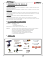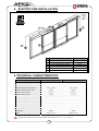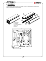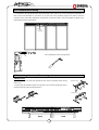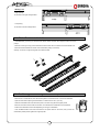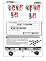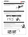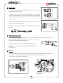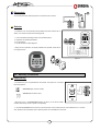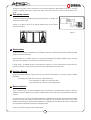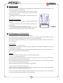
1
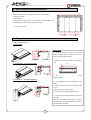
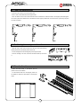
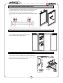
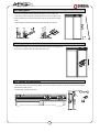
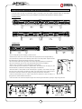
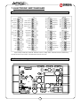
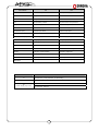
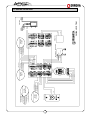
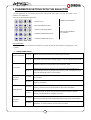
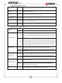
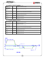
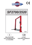
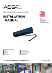
INSTALLATION
MANUAL
Technical Help Line
Tel 08700 434512
Sales Line: 08700 434512
Fax Number: 08700 434524
Email: [email protected]
Website: www.adsf.co.uk
:
ADSF 3000 Heavy Duty
Global Model
240 Kg Total Door Weight
������� �������
���������
INTRODUCTION
ADSF ERREKA Automatic Doors thanks you for the trust placed in us and for having selected a product that we
manufacture. We recommend detailed reading of this installation manual for proper assembly, the performance of your
automatic door will depend on the quality of your work.
ADSF ERREKA Automatic Doors will not be held liable for any damages caused by an installation not in accordance
with this Installation Manual.
CONTENTS
1. WARNINGS FOR THE INSTALLER............................................................................................................................... 2
2. EC CONFORMITY STATEMENT ................................................................................................................................... 2
3. TOOLS KEY.................................................................................................................................................................... 2
4. ELECTRIC PRE-INSTALLATION ................................................................................................................................... 3
5. TECHNICAL CHARACTERISTICS:................................................................................................................................ 3
6. ASSEMBLY..................................................................................................................................................................... 3
7. ELECTRONIC SWITCHBOARD ................................................................................................................................... 14
8. START-UP (Set Up)...................................................................................................................................................... 21
9. PARAMETER SETTING WITH THE SELECTOR ........................................................................................................ 23
10.TROUBLESHOOTING GUIDE..................................................................................................................................... 27
11.ANNEXES .................................................................................................................................................................... 28
1
1. WARNINGS FOR THE INSTALLER
Importance of this manual
- Before installing, please read this manual and follow all instructions. Otherwise, the installation may be faulty and may
cause accidents and breakdowns.
ERREKA Automatic Doors will not be held liable for any damages caused by an installation not in accordance with this
Installation Manual.
Projected Usage
- This product has been designed to be installed as part of automatic opening and closing sliding pedestrian doors. It is
designed for intensive use within the limits of weights indicated on the characteristics. Installation and use is indicated
for use inside buildings.
- Any use for any purpose other than indicated is considered inadequate and therefore dangerous.
Safety element
- The unit meets all current safety standards. Follow the instructions of all the elements you fit in the installation.
- Erreka Automatic Doors doesn´t accept any responsibility for the safety and smooth operation of the door when using
system components other than those produced by Erreka.
2. EC CONFORMITY STATEMENT
Manufacturer,
MATZ ERREKA, S. Coop.
B º San Juan 93
20570 Bergara (GUIPUZCOA) - SPAIN
Product, Operator for automatic sliding door GLOBAL SYSTEM 1450-1850
States that:
The operator has been constructed to be incorporated into the machinery or to be assembled with
other elements to create a machine under the following guidelines and standards:
● Machinery Directive 89/392/EEC and subsequent amendment 2006/42 EEC
● EMC Directive 89/336/EEC and subsequent amendment 92/31/EEC
● Low Voltage Directive 73/23/EEC and subsequent amendment 93/68/EEC
● Construction Products Directive 89/106/EEC
3. TOOLS KEY
∅ 7 DRILL BIT
FLAT SCREWDRIVER
∅ 8.5 DRILL BIT
Nº10 SPANNER
M8 BOLT
Nº13 SPANNER
DRIL
WIRE STRIPPER
CROSSHEAD SCREWDRIVER
Nº4 T-HANDLE ALLEN
WRENCH
Nº 13 SOCKET
WRENCH
CLAMP
2
SPIRIT
LEVEL
4. ELECTRIC PRE-INSTALLATION
Po
El
e
o
c tr
bo
n ic
ar
r
we
Su
pp
ly
d
No.
DESCRIPTION
CABLES
1
Supply
4-wire hose
2
Selector
5-wire shielded
3
485, centralised line connection
2 wires
4
Safety Key
2 wires
5
Radars
4 +4 wires
6.
Photocells
2 +2 wires
5. TECHNICAL CHARACTERISTICS:
Operator 1450
Operator 1850
Clearway (2 sliding-leaves)
CHARACTERISTICS
1000-2300mm
1100-3000mm
Clearway (1 sliding-leaf)
750-1150mm
1000-1550mm
Maximum weight per leaf (2 leaves)
120 + 120 Kg.
120 + 120 Kg.
Maximum weight per leaf (1 leaf)
160 Kg.
160 Kg.
Maximum opening speed
0.9 m / s
0.9 m / s
Minimum opening speed
0.4 m/s
0.4 m/s
Maximum closing speed
0.6 m/s
0.6 m/s
Minimum closing speed
0.2 m/s
0.2 m/s
Maximum closing force
Temperature
Door open timing
Power supply *
Consumption
Battery
150 N
150 N
-20ºC/ +50ºC
-20ºC/ +50ºC
90 sec.
90 sec.
230 V ~ (± 10 %) / 50 Hz
230 V ~ (± 10 %) / 50 Hz
200 W
200 W
Lead (12 +12 v)
Lead (12 +12 v)
* Available upon request, the version of the operator for the supply of: 110 V ~ (± 10 %) / 60 Hz
3
6. ASSEMBLY
This section explains in detail how to perform the installation mounting. For your information the following shows the
profile key and external dimensions of the motorization.
1
2
3
4
1.- Support Profile.
1.- Perfil Caja.
2.- Cover Profile.
2.- Perfil Tapa.
3.- Anti-vibration
rubber band.
3.- Goma antivibración.
4.- Junquillo
4. Support
bead. Caja.
5.- Junquillo Tapa.
5. Cover bead.
5
17
160
165
5
54
70
4
6.1 Measuring the structure beforehand
B
Measure the dimensions of the gap where the door will be installed:
- Clearance height (H)
- Total width (B)
- Define what the Clearway is (PL), the Clearance Height (H) Width of the
H
fixed leaves (FW), and the length of the box profile (B).
B = 2xPL +2xSC +100
FW
PL
SC
FW
SC
6.2 Fitting of the support profile
Support profile fitting variants;
1 .- Wall or UPN
65
165
Steps to follow
1. - Mark the installation height of the support
base of the beam (wall / structure).
60
160
120
98
160
profile. The profile must be set at 60 mm from the
2. - Make holes in the support profile on the marking
lines.
2 .- Erreka Dintel - self supporting Beam 1
max. 3m
165
20
60
160
160
60
3. - Fit the profile in the correct position and drill
holes in the beam.
3 .- Erreka Dintel – self supporting Beam 2
4. - In accordance with the characteristics of the
beam:
60
165
- Screw the holes for fixing the profile with M8
160
160
screws.
- Place anchors bolts to fix with spits.
60
- Fix the support with a special tapping screw.
5 - Secure the support profile. Make sure the profile
is levelled.
(See also the installation drawings and manuals
supplied and the mounting manuals when installing
the Load bearing Structure!).
5
6.3 Fitting the support bead
- Insert the brush into the slot of the support bead.
- Each 1 meter, make drill holes in the support bead.
- Place an M6x16 screw in each holes DIN 7984 and an extended nut. Place the bead in the support profile and tighten
the screws, place the extended nuts in the direction of the support profile track, move the screws up until they stop and
turn them clockwise.
6.4 Positioning the carriages on the rail
- With the size 4 Allen wrench loosen the half-way wheel (anti-derailing
wheel) and move to the lowest position of the slot.
- Put the carriage above the carriageway of the support Profile.
- Once the carriage is on track, move the anti-derail wheel up and secure
it.
6.5 Place the fixed leaves
- Attach the fixed leaves, in accordance with the
profile manual to be installed.
- For fixed leaves with Fine and Gripper profile use
the attacks to attach the fixed leaves to the Support
bead!
6
6.6 Fasten the attack to the mobile leaves
- Fix the attack brackets on the moving leaves as in the drawing, the centre
of the attack must be approx. 130 mm of the sides of the moving leaf.
- Fasten the M8x25 screws with a size13 wrench (2 per attack).
- For all profiles, make the holes at the following measurements at the 2
ends.
92
92
130
130
- With a moving leaf and electrolock the centre of the attack must be approx. at 175mm.
6.7 Hang the leaves on the carriages
- Fix the attacks on the carriages with M6x16 Allen
screws, the toothed washers and flat washers.
6.8 Depth adjustment of the moving leaves
- Use the size 13 wrench to position the moving leaf parallel to the
support profile, then measure the distance between the leaf and the
beam or the wall. Put the 2 ends of the leaf at 5 mm.
22
7
30
6.9 Fitting guide
- Move the moving leaf to find an angle of 90º degrees, to do so use a level.
- At this point, position the guide on the ground at the end of the fixed leaf, with
the block inserted into the moving leaf guide, mark the ground when the blade
is level.
- After attaching the guide to the ground and slide the blade over the wire.
90
°
6.10 Height adjustment of the leaves
- Adjust the leaf height using the central screw of the carriage. This regulation is
very important, the leaves must be parallel when they meet.
Tornillo de
regulación
6.11 Placing the limit switch
- Place a limit switch where the moving blades meet, to do so insert 2 long nuts on the rail and fasten the limit switch
stop with M6x10 Allen screws.
- The other limit is placed on one side.
Tope lateral
8
6.12 Preparation of wiring
- It is advisable to pass peripheral device wiring (photocells, radars, selector, etc.). before placing the motorization, as
there is little room afterwards for your hands. Try to pass them to the positioning height of the frame to make the
connection to the frame easier afterwards. Use grommets to attach the cables, which are supplied and placed in the
support profile (see the picture below).
Posicionado
Wiring
del cableado
positioning
Use a screwdriver to remove the grommet!
Cables
6.13 Attaching the arms of the carriages
2 Sliding leaves
- Fix the separating nuts with DIN 7984 M6x16 allen screw and splined washer using a
Right inner carrier
wrench nº10.
- The arms must be installed as follows: the right arm in the up position (inside right carrier)
and left in the down position (inside left carrier.)
Left inner carrier
9
1 Sliding Leaf
- Right opening
Fix the arm to the right carriage above
- Left opening
Fix the arm to the left carriage below
6.13 Fit the Brackets to the belt
- Insert Brackets (1) and (3) on the belt at the same number of teeth with respect to each one of the
pulleys.
- Place the covers (2) and (4) on the brackets and secure them with 2 countersunk screws and M6 nuts.
- Move the bracket towards the centre of the motorization pulling on the strap.
Warning: In case of a single moving leaf one bracket is fitted.
2
4
3
1
6.14 Positioning and fastening the motorised profile
- Remove the 4 screws M6x16, flush with the elongated nut and leave them on the rail as illustrated.
- Open the doors before placing the motorization, so that arms are not in your way.
- Hold the motorization with both hands and push it until it fits snug with the support profile.
- Move the set inward so that it fits into the tabs. Once seated, the motorization can be released.
- Position the motorisation to the side depending on the type of installation.
- Push the M6x16 Allen screw until it touches the box profile and turn the screw, until you see the
motorization profile press it against the support profile.
10
Lift the profile up until it
comes to a stop
Move towards the support profile
Push the screw upwards
Turn clockwise
Place the motorization in the support profile
-2 sliding leaves: IN THE CENTRE
- 1 right opening sliding leaf: ON THE LEFT
100:200
- 1 left opening sliding leaf: ON THE RIGHT
100:200
6.15 fasten the brackets to the arms
- Release slightly the countersunk M6x12 screws, which the brackets have
been attached, to move one of the moving leaves. When M6 nuts, used to
attach the bracket are located within the arm rail, fasten the M6 countersunk
screws with a size 4 Allen wrench.
- Move the 2 loose-leaves until they meet, then fasten the other bracket, to the
other arm, perform the same operation and carry out a manual check of the
movement for the leaves to the end of the course.
11
Slightly
loosen
Tighten
6.16 Place the rubber and the side covers in the SUPPORT profile
- Place the rubber (on the entire length) in the support profile.
- Place the side covers, securing them to the support with tapping
screws ∅ 4.2x13 countersunk head.
Goma
6.17 Put the cover positioners
- Place the elongated nuts in the direction of the rail support profile, move the screws up until they stop against the
profile. Turn the key clockwise and set the positioner plate to the support.
- Place the two positioners brackets.
- Put the positioners in the cover profile. These should be at the same height of the bracket set in the support profile!
6.18 Secure the cover profile
- Drill two 6.5 mm diameter holes at both ends of the cover profile.
- The distance from the centre of the hole to the end should be 12mm.
- Attach the hanging system cables (one at each end of the machine) to the support profile and to
the cover profile, as shown in the figure.
- To fit the cover profile, first lean the end of the cover on the ball of the support profile. Supporting
the profile let it fall under its own weight which the lid pivots. Finally, set the profile to the side
covers using two M6x15 screws (one at each end).
Note: For maintenance you can leave the lid attached by the support profile or suspended by the
hanging cords.
12
6.19 Electrolock assembly and manual unlocking
If the door does not have any electrolock system, go directly to the next chapter, otherwise follow the instructions
mentioned below. Depending on the type of installation, the electrolock will be placed in different positions:
2 sliding leaves
1 sliding Leaf
- Fix the "Locking plate (2) to the" Carriage "(1) with two screws.
- With the door open insert, more or less in the middle of the support profile, the two "Elongated Nuts" (3).
- Fix the "Electrolock" (9) with two screws. Manually, take the door to the closed position. Adjust the location
of the Electric block so that the electromagnet couples the "Locking plate."
- Place the "Release cable bracket" (4) at 60mm on the left (or right as appropriate) of the "Electrolock".
- Place the "Unlock puller" (5) at one end of the support profile (right or left as per installation)
- Slide the "Case" (7) between the "Unlock Cable Support" (4) and Puller (6).
- Pass the "Cable" (8) from the "Electrolock" to "Release Puller." Be careful to insert the "Spring" (11) and
“The Brass Bracket" (10) between the "Unlocking Cable Support" and "Electrolock".
- With "Unlock Puller " in down position and the "electromagnet" in up position, cut the "Cable" to the height
of the base of the "Unlock Puller" and attach the "Cable" to the puller with the catch. Pulling the lever to
control that the "Electrolock" unleashes the carriage and dropping the" Electrolock "it falls down.
- Fasten the "Brass Bracket" (10) to the "Cable" so that when the "electrolock" is down the "Spring" (11)
gently pushes the "Cable" towards the "Electrolock"!
- Connect the wires to the control board. Adjust the length of the cable using the terminal block, specially on single moving leaf doors.
Inner unlock
7
4
11
Internal and external unlock
3
10
Desbloqueo
exterior
8
6
5
1
9
2
13
7. ELECTRONIC SWITCHBOARD
7.1 Connection terminals
N33VAC
Tierra
L33VCA
N12VAC
L12VAC
Alarma 1
Alarma 2
Out.exclusa1
Out.exclusa2
GND
61 62 63 64 65 66
Reset
56 57 58 59 60
SW2(Negro)
Reset
MOTORREDUCTOR
SW1(Rojo)
BAT. EMERGEN.
45 46 47 48 49 50
40 41 42 43 44
GND (Marr.)
RELES AUX.
RESET ELECTROBLOQ
ALIMENTACION
ALRM
+12 (Azul)
51 52 53 54 55
485-B
EXCLUSA
485-A
485-GND
485
11 12 13 14 15 16 17
P-GND
PHOTOCELL
10
P+12V
ANTIP
9
Antipanico2
EXCL.
Antipanico1
Fotocelula1
RADARS
Inp.Exclusa2
8
GND
Inp.Exclusa1
7
Tx
6
CLK
P-GND
Fotocelula2
SELECTOR
Rx
Radar externo2
5
+12
LLAVE
Llave-B
28 29 30 31 32 33 34
Llave-A
Radar externo1
4
P-GND
Radar interno2
3
Sensor seg2
SENSOR SEG.
Sensor seg1
24 25 26 27
P+12V
2
Receptor2
Radar interno1
DOWN
UP
1
Masa común
LENTES-B
Emisor2
LENTES-A
Receptor1
18 19 20 21 22 23
Masa común
UP
P+12V
35 36 37 38 39
DOWN
Emisor1
Motor +
Motor P-GND
Encoder 1
Encoder 2
P +12V
Batt+
BattEmerg.11
Emerg.2
GND
Aux2-A
Aux2-B
Aux1-A
Aux1-B
Antena
Inputs normally closed (NC): Photocell: terminals 12 and 13, Safety sensor: terminals 25 and 26; External key:
terminals 28 and 29; Input "switch" of the electrolock, terminals 47 and 48.
7.2 Control panel diagram
14
LED DIODES
VAC
ON
OFF
220V network present
Lack of power supply
ENC1
1st signal via the encoder
ENC2
2nd signal via the encoder
+5 V
Microprocessor powered
No power to the microprocessor
INSIDE RADAR
Inside radar input closed
Inside radar input closed
OUTSIDE RADAR
Outside Radar Input closed
Outside radar input open
PHOTOCELL (NC)
Photocell input closed
Photocell input open
SAFETY SENSOR (NC)
Safety sensor input closed
Safety sensor input open
EXTERNAL KEY (NC)
External key input closed
External key input open
EMERGENCY
Emergency input closed
Emergency input open
RESET
Performing reset operation
+12 V
Adequate power to peripherals
No power to peripherals
LOCK
Electrolock latch released
Electrolock latch blocking
SW-ON
Emergency signal activated
Emergency Signal Off
IN BARRIER
Airlock input activated
Airlock input deactivated
OUT BARRIER
Airlock output activated
Airlock input deactivated
ANTIPANIC
FUSES
MEANING
F1
Fuse 5x20 8 A ( motor protection. 1st Secondary)
F2
Fuse 5x205 A (protection input peripherals. 2nd Secondary )
F3
(Power Supply Input fuse)
For 220V fuse 5x20 2A
For 110V Fuse 5x20 4A
15
External key
SAFETY
SENSOR
4- GND (power)
1- +12 (power)
R.In.2/ R.Out.2 (signal)
R.In.1/ R.Out.1 (signal) NO
13- Phot.2 (signal)
12- Phot.1 (signal)
16
28- C
28- A
27- GND (power)
26- Sen2 (signal)
25- Sen1 (signal)
24- +12 (power)
RADAR +
PHOTOCELL
30- +12
31- Rx
32- CLK
33- Tx
34- GND
4- GND (power)
1- +12 (power)
2- R.In.1 (signal)NO
3- R.In.2 (signal)
Com Tx CLK Rx +12
AUTOMATIC DOORS
Selector
INSIDE
RADAR
1- +12 (power)
14- GND
13- Phot.2
12- Phot.1
11- +12v
-
NC
(com)
+
Power
Amplificateur - Photocelllule
6- GND (power)
5- R.Out.2 (signal)
4- R.Out.1 (signal)NO
58- Em.1
57- Em.2
50- +12
49- GND
Electrolock
GLOBAL SYSTEM
Emergency
OUTSIDE
RADAR
7.3 Standar connection
Photocells
Place the amplifier in the motorization assembly or support profile. Secure it with the
adhesive tape that the box contains.
- Install the transmitter photocell lents, receiver/transmitter in its corresponding
position according to profile type. If installing 1 photocell, this will be placed at 500
mm from the ground. If you are installing 2; one at 1000 mm and the other at 200
mm from the floor.
Diagram 1
- Pass the transmitter and receiver cables through the grommets to the photocell
amplifier and make the following diagram 1.
11- +12v
12- Phot.1
13- Phot.2
- With a 4-wire hose make the connections from the amplifier to the frame, shown in
14- GND
diagram 2.
Amplifier
+
(com)
NC
-
Power
Diagram 2
Diagram 2
Network connection
- Pass the cable over the cable gland and then clip it into the support profile and take it to the power supply unit. To do
this strip the wires and attach the connector on the end, then insert the
connector onto the base situated in the power supply.
In the event of mains failure, the function selector will indicate "Err5."
Warning: Power supply batteries must be replaced by SAT staff at least
every three years.
Radars
- Connect the internal radar directly to the frame, take the outer radar cable to the left side of the motorization by the
UPN, make a hole through the support profile and pass the cables through the grommets to the frame.
- To make the connections follow up the diagram 3.
2
1.-1.-Radar
Inside Interior
radar
Outside
radar
2.-2.-Radar
Exterior
Diagram 3
17
1
Electrolock
Connect the electrolock assembly terminal in the frame input connector
50- +12
49- GND
Selector
- The selector is the communication device between the frame and the user, it
allows us to control and perform the following tasks:
1.- Choice of different operating modes of the automatic device.
2.- Regulation of operating parameters.
3.-On / Off options.
AUTOMATIC DOORS
4.- Faults and failure modes diagnosis.
Com Tx CLK Rx +12
- During the door operation, the display indicates the operation mode that is
34- GND
running at that time.
33- Tx
32- CLK
31- Rx
30- +12
Diagram 4
ADSF
5.4 Auxiliary Connection
External key
- The external key is a lock operated from the outside. The input is NC. It contains
these two positions:
ADSF
Deactivated (the contact is closed)
28- A
Activated (the contact is open)
28- C
- When the lock is in the Deactivated position, the door is in the “Door Closed”
condition and locking comes on (if this is incorporated).
- In the activated Position the door returns to the last function it was in before the lock was enabled. Even in a "Closed
door" status the door will always open to allow the person who activates the lock to enter.
18
To leave from the inside, if the key is activated; you can leave by pressing the "EXIT" selector or the key “1". From the
moment it is pressed it will remain 1 minute in the "EXIT" mode. After one minute, it returns to the key mode or door
closed.
Side safety sensor
- This avoids people being trapped during the opening operation, by stopping and
24- +12
25- Sen1
continuing at a slower speed.
26- Sen2
27- GND
Warning: If an object is placed in the sensors detection area, the door will be
opened in slow motion.
Diagram 5
Reset button
We will use the rest buttom if the Selector is not installed. In this case, its performance would be to activate the Reset
operation to start the motorization.
When the Selector is not installed, the door can only perform the Bidirectional Automatic operation directly, we cannot
perform any other operation, such as Open Doors, Close Doors, Exit only....
In these cases, it is advisable to place a reset button (for example in one of the side panels for cases where it is
necessary to perform a "reset") so that the door will recover the parameters (in any other case).
Auxiliary Relays
Voltage free contacts that give a signal in the door open and door closed positions. They may be used for different
applications.
For example: Connection to a door open or closed indicator lamp.
Aux1: terminals 52, 53. Switch on in door open position.
Aux2: terminals 54, 55. Switch on in door closed position.
Barrier function
This is a function that is only valid for installations with two parallel doors, one located behind the other. It offers the
possibility of interconnecting two PLC´s to perform a discriminatory function. Each door will only operate if the other door
is closed.
To clarify this function, we will give the following explanation: a pedestrian moves forward and once he/she has passed
through the first door and is facing the second door, this second door will not begin to open until the first one has
actually closed. Although the sensors detect the presence of a pedestrian (on both sides of the door) the control board
will not consider the signal until the first door is completely closed.
This is very useful as a security or access control system.
19
Remote control
This accessory consists of a 433MHz four-channel transmitter at and receivers that connects directly into the frame. The
remote control allows 2 modes of operation:
1. - Reduced selector, which activates three modes of operation. These are
"Door open" "Door closed" and "Automatic" mode. The three modes are
indicated above each button.
2 .- Release pulse, which makes every pulse on the remote control open the
door.
Programming the transmitter
To program the transmitter with the receiver
the following steps should be
carried out:
1. - Choose a code by fitting the 8 emitter dipswitch (see figure) in the
1
2 3 4 5 6 7 8
0
-
desired position.
2. - Push one of the transmitter buttons and keep it pushed.
3 .- Then, press the button of the receiver with it being inserted into the
frame. Keep it pressed until the led on the receiver performs 3 blinks.
Civil Emergency / Fire Prevention
For emergency situations, 10 and 6 input terminals will be used.
For operating, this input will take precedence over all others. This is normally connected to the building's fire alarm,
that´s why this function will take priority over the others, as it concerns personnel safety.
There will be 2 emergency mode options, one door will open and the other will close. You also have the option of 2
types of input signal.
Functioning Mode:
1.- From functions "--++"( FunC) "3" (AI-0)
(AI-0): When you enter the signal, the door will go to total opening and it will remain in this position as long as the
emergency signal is maintained.
(AI-1): The door will close without regard to the radars, just the photocells. After the door is closed it will remain in this
position as long as the emergency signal is maintained.
Signal type
The opportunity to make an emergency signal or an occasional signal will be given.
2 .- From "--++" functions (Func) "6" (LA-0)
(LA-0): Continuous and uninterrupted signal. As long as the door signal operates in the emergency mode, when the
signal leaves it will revert to the previous working mode.
(LA-1): Signal point. With a signal, the door will go to the emergency mode and it will remain in this mode. The mode will
return to normal operation by resetting from the frame.
When the emergency signal enters, it should appear on the display (Err6).
- Emergency power when the electrical supply leaves:
If power is lost and the emergency signal starts the emergency operation will have priority. Therefore with or without
power, the behaviour of an emergency signal is the same.
In the even of a power cut, before entering the emergency signal, if the door open was open in "Err-5" it would remain
open (in case of "Err6") but with the emergency warning on the display.
20
8. START-UP (Set Up)
Once the door have been installed, the automatic device and the function selector, they should be connected to the
power supply:
1 .- Connect all the peripherals (sensors, photocells, selector, etc.) to the frame.
2 .- With the cover profile raised we plug in the mains connector in its position of the power supply unit. Press the twoway switch that activates the source, input and batteries. At this point, the reset or initialization operation starts
automatically. The lid is closed while the door performs the operation.
The Reset operation is always carried out on starting up the door for the first time. Its function is to measure the course
of the leaves, set their initial values for all the parameters and start the counters. The operation is an opening cycle to
the end of the course, followed by closing until the two leaves meet. During this cycle the switchboard
makes the
mentioned measurements and is ready to begin normal operation.
3 .- With the function switch connected, you must perform the initial setup (SET UP). To do this, you must press the
keys in sequence "+ - - +" and the code (the release number). The default release number is "1 1 1 1".
The door will start a second reset manoeuvre, but in this case it also calculates the weight of the leaves and
automatically saves on the memory the appropriate curve for the weight conditions and width of the leaves.
4 .- Once the Reset has finished the door goes into the "Door closed" status. At this time, we are in a position to
command the door from the selector to choose the operating mode.
If the selector is not installed, it passes directly to “two-way automatic."
If it were necessary to modify the operation parameters, we would put the door on the "open Door" mode which is the
normal working mode. We have the option of varying the initial parameters for others that we feel most appropriate for
the installation. In this case we will up follow point 9 "PARAMETER SETTING WITH THE SELECTOR”.
5 .- Once the performance has been adjusted to suit the client, the working mode can be selected from the selector.
8.1 Working Modes
Are the different types of operation or states in which the door can operate. This automatic device offers 6 different
working modes:
1 .- Door open
( OPEn)
The door opens and remains open in the maximum opening position.
2 .- Door closed
(CLSE)
The door closes and stays closed in this position until the mode remains unchanged. If you install the electrolock, the
door will close and lock so that no one may enter.
3 .- Two-Way Automatic
(AU - b)
This is the most common way of working. This mode allows traffic in both directions, so that all the detection devices are
enabled. The door remains closed until one of the devices is not activated. If any of these activates the door, it opens
and after a hold-open time (adjustable) it is closed again until further detection.
21
4 .- Partial Automatic
(AU - P)
These operates the same way as the two-way automatic mode, but with the difference that the leaves do not open to
the maximum openness. This opening is adjustable by the user (see point 6).
(OPE n)
5.- Door partially open
This mode does not really have its own key. It is the same as door open and it functioning is also equal to the difference
that the door stops in a partially open position.
This mode comes only in the case that the door has been in the "Partially automatic mode." If you want to return to
"door open (total)" first press the " two-way Automatic " mode.
(EXI t)
6 .- Only Exit
It allows traffic to exit in the outside direction. In this direction, it works as "Two-way automatic" and in the entry mode
"Door Closed ".
22
9. PARAMETER SETTING WITH THE SELECTOR
To enter adjustments we must always start from the working mode "Door Open". From any other mode it is not
possible to enter adjustments.
There are 5 levels of adjustable parameters:
NORMAL ADJUSTMENTS
Functions (Func)
MAIN PARAMETERS (PARA)
SPECIAL FUNCTIONS (ESPE)
SPECIAL ADJUSTMENTS
OPENING PARAMETERS (PAAP)
(For installers)
CLOSING PARAMETERS (PACL)
List of parameters.
To enter programming you should follow the sequence of 4 pulses one after the other indicated by pressing the "+" and
"-" selector.
- - + + FUNCTIONS (FUnC)
"1" (rF-0)
Selector: the remote control works as a selector (Three channels)
"1" (rF-1)
The remote control generates an opening impulse. To use with a single-channel remote.
"2" (rC-0)
Disable the delay-timer to the activation of the "Closed Door" mode.
Emitter configuration
Closing delay
Enable the delay-timer to the activation of the "Closed Door" mode. So that until you
"2" (rC-1)
pass the set time the door only operates in the "Exit Only" mode. Once past the time (90
sec) it will automatically switch to "Doors Closed".
"3" (EF-0)
Emergency
Behaviour
"3" (EF-1)
"4" (bA-0)
Door open: When activated the door signal places itself in the open position and remains
in this position.
Door close: When activated the door signal places itself in the closed position and
remains in this position.
Panic mode. In the case of mains power failure, the door opens and stops during the
opening. If the door is in Doors Closed position it will be kept in this position.
Battery Operation
"4" (bA-1)
"6" (ES-0)
Emergency
Behaviour
"6" (ES-1)
Autonomous mode: In case of mains power failure the door continues to operate
normally until the batteries are completely running out.
Continuous emergency signal. To maintain emergency operations the active signal must
be maintained. When the signal is deactivated the door returns to the normal operation.
Timely emergency signal. A single impulse activates emergency behaviour and
maintains it. To restore operation, you have to carry out a reset.
23
- - + - MAIN PARAMETERS (PARA)
Slowing down at
closing
Percentage of partial
opening
Slowing down on
opening
Opening speed
Waiting time on
opening
Closing speed
"1" (bc-0)
"2" (P-50)
"3" (ba-5)
"4" (A-55)
"5" (E-03)
"6" (C-30)
Standard value, (bc-0).
Regulation; from 01 ( max. force) to 09 ( min. force)
Standard Value, (P-50). 50%
Regulation; from 30 to 70%.
Standard value, (bc-5).
Regulation; from 01 ( max. force) to 09 ( min. force)
Standard Value, (A-55). 0.55 m / sec
Regulation; from 0.50 to 0.90 m / sec
Standard value (E-03),, 3 seconds.
Regulation; from 0 to 20 seconds
Standard Value, (A-30). 0.3 m / sec.
Regulation; from 0.20 to 0.50 m / sec
-++-SPECIAL FUNCTIONS (ESPE)
"1" (SP-0)
Disables the pulse sensitivity, less sensitivity.
"1" (SP-1)
Triggers pulse sensitivity, greater sensitivity.
Sensitivity
Standard; When an obstacle is detected on closing the door it will open at slow motion
"2" (CA-0)
and close at normal speed. When it detects an obstacle on opening the door it will open
at slow motion (After 10 attempts, if the obstacle still remains, the door closes at normal
speed).
Obstacle Detection
Special, when it detects an obstacle when closing the door, it opens and closes using
slow motion. When an obstacle is detected 3 times consecutively on closing, the door
"2" (CA-1)
stops on opening. To restore operation, you have to carry out a reset. When an obstacle
is detected on opening, the door stops and opens using slow motion. When an obstacle
is detected on opening 3 times consecutively the door will stop and beep. To restore
operation, you have to carry out a reset.
Reset Settings
"3" (CR-0)
When the switchboard is supplied, the door automatically performs a reset.
"3" (CR-1)
When the electric switchboard is powered, the door performs a Reset if the external key
is activated.
Automatic /
"4" (AU-0)
Semiautomatic
"4" (AU-1)
"5" (nb-0)
Battery Monitoring
Automatic. Normal operation of the door carrying out a full cycle for each activation
signal (opening and standby and closing).
Semiautomatic. Each activation a half cycle is performed. A pulse opens and another
closes.
Monitoring function off.
Monitoring feature is enabled. Battery load level readings performed continuously. If the
"5" (nb-1)
batteries are discharged or broken the door will go to open position and a “BATT"
flashing sign will appear in the selector.
Door Address
"6" (d-00)
Parameter to consider in the case of installing centralized control. You must assign a
different address to each door connected to the system (from 0 to 99).
24
+ + - + OPENING PARAMETERS (PAAP)
Final speed on
opening
"1" (FA.02))
Minimum speed
deceleration on
"2" (UA.04)
opening
Sensitivity on opening
Ramp acceleration on
opening
Deceleration point on
opening
Deceleration ramp on
opening
"3" (SA.09)
"4" (AA.8)
"5" (PA.65)
"6" (DA.85)
Standard value, (FA.02).
Regulation; From 01 min. to 15 max.
Standard value, (UA.04).
Regulation; From 01 min. to 10 max.
Standard value, (SA.09).
Regulation; From 01 more sensitive to 09 less sensitive.
Standard Value, (AA.8).
Regulation: From 08 max. to 20 min.
Standard Value, (P-50).
Regulation; From 40 to 85.
Standard value, (DA.85).
Regulation; From 70 to 95.
+ + - - CLOSURE PARAMETERS (PACL)
Final closing speed
"1" (FC.02))
Minimum
deceleration speed
"2" (UC.03)
during closing
Sensitivity close
Acceleration ramp on
closure
Deceleration point on
closure
Deceleration ramp on
closure
"3" (SC.09)
"4" (AC.10)
"5" (PC.65)
"6" (DC.85)
Standard value, (FA.02).
Regulation; from 01 min. to 15 max.
Standard value, (UA.03).
Regulation; from 01 min. to 10 max.
Standard value, (SA.09).
Regulation; from 01 more sensitive to 09 less sensitive.
Standard Value, (AA.10 ).
Regulation: 08 max. to 20 min.
Standard Value, (P-65).
Regulation; from 40 to 85.
Standard value, (DA.85).
Regulation; from 70 to 95.
25
Keypad Lock
→ cod 1 + Timer (10 sec) →DEFAULT LOCKING WITH CODE
↓
Cod 2 (displayed on the screen
when we enter a
new code, e.g. “3458”)
↓
CODE (the code should be repeated, so it will be
recorded)
After 10 seconds of pressing 4 times the "+", locking will come into action and the working mode corresponding with the
points below each each digit "P. -. A.b." will appear in the display.
The code must be any number from "1111" to "9998".
Unlock
From any working mode, enter the predefined code. Once pushed, the points of display disappear and the selector will
be activated.
Return to the initial parameters
In some cases after making the adjustments of the displacement curves, we can reach the point where we deem that
the curve calculated by the micro in the first "Reset" was better. In this case, we would have the option of returning to
the initial curves.
+ CODE (the unlock number)
At this time, the operator starts an operator reset and re-deploys the initial curves.
26
10. TROUBLESHOOTING GUIDE
SYMPTOM
- Conducts a reset slower
than normal.
DETECTION.
SOLUTION
- Diode LED, VAC off
Lack of power supply
- Check the fuse (5x20 2A) of the power supply.
- Check the fuse (5x20 8A) of the protection to the motor.
- Check if the wires are connected to the power supply and the frame.
- Display; Err5.
- After the reset, if we set to
"Automatic", the door will
open and "Err5" appears in
the display.
- On conducting a reset the
door remains open and will
not close. The alarm reset
continues beeping
- LED Diode; Photocell (NC)
off
- Check if the photocell is operating properly.
- After reset, the door
remains closed even though
there are attempts to change
it from the selector.
- Diode LED, External key
(NC) off
- Check if the key is in the closed position.
- When the door works on
automatic and detects the
radar
to
reverse
the
movement, it goes to open
doors at full speed without
braking and gives a strong
blow when reaching the end.
- No power, the motor does
not move and does not go to
open door.
- The display shows "Err6."
- The door is automatic but
does not open on the radar
pulse.
- If the door has no outer key, check the outer key terminals outside of the
switchboard are bridged.
Check the motor
cables. Position:
power
- Connect the cables as indicated. Both, supply and the encoder.
RED (motor power)
BLACK (motor power)
BLACK (encoder power)
GREEN (signal encoder 1)
YELLOW (signal encoder 2)
RED(Encoder supply)
Could be on "CLSE"
- The batteries have no
power or they are poorly
connected.
- Diode LED, Emergency on.
- Safety Diode Sensor (NC);
If it is off ,the door can never
open.
- This is okay, because during door closed status the door not need to be
opened.
- Check the battery connection at the source. Measure with the multimeter
the output voltage of the batteries.
- Change the batteries, if these are empty.
- Reset the door. If it returns to door open mode and error 6, check the
emergency entry, the fire alarm signal.
- Check the frame connections.
Detection and elimination of friction:
- Manual movement of the
door forced.
- Rubbing.
- During manual opening or
closing of the door, knocks
are heard.
- Contact of the moving parts
of the door with fixed parts.
- Door opens during the reset
but does not close in some
cases, it can start closing
and return halfway.
- Photocell in disrepair, not
connected or acting.
- Check status of the photocell.
- Power Transistor to motor
broken.
- Replace transistor or plaque.
- During opening or closing
the door stops or recedes.
- Contact friction.
- See mechanical problems.
Indication
of
battery
discharged, or broken, the
door remains in open
position.
- "Batt" appears on the
selector display
- If you see this BaTT intermittently more than one day in a row, you should
change the batteries as they may be broken or discharged below their cutoff.
- Separating the door rubbing with wall or fixed parts.
- Raising the door or door friction guide block or ground.
- Cleaning rolling channel (chips).
Detection of such contacts:
- Carriage contact with the fastening screws of the box. Tighten the screw
or use a screw with smaller heads.
- Carriage clamping arms of the door carriage with the belt on the processor
or CPU boxes. Straighten the arm to ensure that it does not knock.
27
11. ANNEXES
11.1 Maintenance
Automatic door installations require regular maintenance; the frequency will be determined by environmental conditions
and traffic density.
1.- Remove dust and dirt from the mechanism. Dirt on the running track should be removed with methylated spirits.
2.- No part requires lubrication. The timing belt should be kept dry and clean.
3.- Check that all nuts and bolts are secured.
4.-Adjustment, if necessary only, the speeds of the moving leaves, the opening time held and that the position of the
moving leaves are in accordance with existing regulations and requirements of the authorities.
11.2 Warranty
AUTOMATIC DOORS ERREKA declares under their sole responsibility that the products supplied are subject to
warranty for a period of 12 months from the date of acquisition. (Date of Work Delivery Protocol) This warranty applies
to all manufacturing defects and will include the costs of transporting the material to the nearest approved technical
service. It is the installer's responsibility to transfer the equipment to this technical service.
This warranty does not include:
• Damage caused by incorrect installation or use of equipment.
• Damage caused by handling by unauthorized personnel.
• Damage caused by external or atmospheric agents (lightning, floods, etc).
28
“CE”DECLARATION OF CONFORMITY
Manufacturer :
MATZ-ERREKA, S.Coop.
Pol. Ind. San Juan 93
Bº San Juan
20570 Bergara (Gipuzkoa) SPAIN
Type of equipment: AUTOMATIC SLIDING DOOR
Mode:
GLOBAL SYSTEM
This equipment was tested, evaluated and found to comply with the following Standard and
Directives:
Powered pedestrian doors
prEN 12650-1, pr EN 1650-2
Safety at powered doors for pedestrian use BS 7036
Low voltage directive
Electromagnetic compatibility directive
Machinery directive
Construction products directive
73/23/CEE
89/336/CEE
89/392/CEE - 91/368/CEE – 93/44/CEE
89/106/CEE
Compliance with standards listed above give presumption of conformity with the requirements of
directive they are harmonized to. Additional requirements may apply before placing on the market is
legal e.g. Declaration of Conformity, the CE marking, technical documentation
prepared/filed/updated and factory quality control.
Ibon Muruamendiaraz
Technical Manager
Bergara, February 10th of 2011
29
NBS Specification
ADSF 3000 Global Model Heavy duty bi-parting sliding door system
The Global System operator can be adapted to the needs of each installation. It is prepared
for heavy traffic, both in large (supermarkets, hotels, airports, hospitals . . .) and in small and
medium buildings (offices, chemist’s, restaurants, points of sale in general . . .) . Its most important
features are its silent movement when opening and closing, dynamic stability and its quick and
easy installation .
All equipment is designed to meet the rigorous safety requirements of BS 7036:1996 and is
installed by Automatic Door Suppliers Association (ADSA) accredited
. engineers
Standard details for ADSF 3000 bi-parting sliding door system
•
•
•
Supplier
Product reference
Door configuration
•
Drive operation
Bi-parting, no fixed panels
Bi-parting, two fixed panels
Standard
•
Door leaf width
700mm - 1500mm
•
Door height
2000mm - 3000mm
•
Finish
Anodised silver
Polyester powder coated standard BS colours
Polyester powder coated standard RAL colours
•
Glazing
As standard
Double glazed - available on request
•
Control
Digital Selector or Key switch
•
Safety & security
Intelligent self learning movement and presence sensors
across door threshold
Rear edge presence sensors for back of door safety
Monitored battery backup (provides up to 30 minutes operation
in the event of a mains power failure)
CHARACTERISTICS
ADSF UK LTD
ADSF 3000 Global Model Heavy Duty
Operator 1450
Operator 1850
Clearway (2 sliding-leaves)
1000-2300mm
1100-3000mm
Clearway (1 sliding-leaf)
750-1150mm
1000-1550mm
Maximum weight per leaf (2 leaves)
120 + 120 Kg.
120 + 120 Kg.
Maximum weight per leaf (1 leaf)
160 Kg.
160 Kg.
Maximum opening speed
0.9 m / s
0.9 m / s
Minimum opening speed
0.4 m/s
0.4 m/s
Maximum closing speed
0.6 m/s
0.6 m/s
Minimum closing speed
0.2 m/s
0.2 m/s
Maximum closing force
150 N
150 N
-20ºC/ +50ºC
-20ºC/ +50ºC
Temperature
Door open timing
Power supply *
Consumption
Battery
90 sec.
90 sec.
230 V ~ (± 10 %) / 50 Hz
230 V ~ (± 10 %) / 50 Hz
200 W
200 W
Lead (12 +12 v)
Lead (12 +12 v)
NBS Specification
ADSF 3000 Global Model Heavy duty single sliding door system
The Global System operator can be adapted to the needs of each installation. It is prepared
for heavy traffic, both in large (supermarkets, hotels, airports, hospitals . . .) and in small and
medium buildings (offices, chemist’s, restaurants, points of sale in general . . .) . Its most important
features are its silent movement when opening and closing, dynamic stability and its quick and
easy installation .
All equipment is designed to meet the rigorous safety requirements of BS 7036:1996 and is
installed by Automatic Door Suppliers Association (ADSA) accredited
. engineers
Standard details for ADSF 3000 single sliding door system
•
•
•
Supplier
Product reference
Door configuration
ADSF UK LTD
ADSF 3000 Global Model Heavy Duty
Single sliding no fixed panel
Single sliding one fixed panel
•
Drive operation
Standard
•
Door leaf width
700mm - 3000mm
•
Door height
2000mm - 3000mm
•
Finish
Anodised silver
Polyester powder coated standard BS colours
Polyester powder coated standard RAL colours
•
Glazing
As standard
Double glazed - available on request
•
Control
Digital Selector or Key switch
•
Safety & security
Intelligent self learning movement and presence sensors
across door threshold
Rear edge presence sensors for back of door safety
Monitored battery backup (provides up to 30 minutes operation
in the event of a mains power failure)
Operator 1450
Operator 1850
Clearway (2 sliding-leaves)
CHARACTERISTICS
1000-2300mm
1100-3000mm
Clearway (1 sliding-leaf)
750-1150mm
1000-1550mm
Maximum weight per leaf (2 leaves)
120 + 120 Kg.
120 + 120 Kg.
Maximum weight per leaf (1 leaf)
160 Kg.
160 Kg.
Maximum opening speed
0.9 m / s
0.9 m / s
Minimum opening speed
0.4 m/s
0.4 m/s
Maximum closing speed
0.6 m/s
0.6 m/s
Minimum closing speed
0.2 m/s
0.2 m/s
Maximum closing force
150 N
150 N
-20ºC/ +50ºC
-20ºC/ +50ºC
Temperature
Door open timing
Power supply *
Consumption
Battery
90 sec.
90 sec.
230 V ~ (± 10 %) / 50 Hz
230 V ~ (± 10 %) / 50 Hz
200 W
200 W
Lead (12 +12 v)
Lead (12 +12 v)
RETURNS NOTE
Please include this form with any items returned
CUSTOMER DETAILS
YOUR REFERENCE:
DATE:
ACCOUNT NUMBER:
COMPANY NAME:
CONTACT NAME:
ADDRESS:
POSTCODE:
TEL:
FAX:
E-MAIL:
Goods
QUANTITY
INVOICE No.
Replacement
Ordered
ACTION NEEDED
Credit
Fault Description
Date Purchased
Repair
TERMS AND CONDITIONS
1. Goods will not be accepted back without a valid Returns number.
2. Please ensure the relevant invoice is placed inside the component box with a detailed fault report.
3. Please give as much detail as possible regarding your fault report .Reports like DEAD or FAULTY will not be accepted.
4. All items including swing operators must be sent back complete, we will not accept individual internal components for repair or replacement.
5. Goods found not to be faulty may incur a testing fee handling charge of £10.00 plus vat.
6. Physically damaged items will be rejected.
7. Items may be replaced with equivalents if originals are not available.
8. These items may be repaired or replaced.
9. Refunds and credit notes are issues at Auto Doors & Shopfronts discretion as point 10 below.
10. Re-stocking:
* The goods have not been installed.
* The goods are returned as complete items.
* All packaging, fixing kits and instructions are as new.
* A re-stocking charge of 15% will be imposed.
Send to ADSF UK LTD Unit 3 Millers Court, Windmill Road, Kenn, Clevedon BS21 6UL
PLEASE SIGN BELOW TO ACCEPT OUR TERMS AND CONDITIONS
ERREKA
Registered Office: 20 –22 Bedford Row, London WC1R 4JS. Registration No. 5287944
VAT No. 811346 362
notes