1
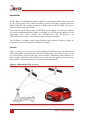
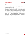
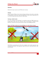
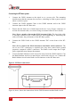
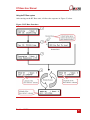
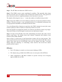
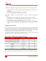
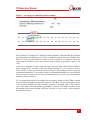
RT-Base GNSS Base Station RT-Base User Manual Confidently. Accurately. Legal Notice Information furnished is believed to be accurate and reliable. However, Oxford Technical Solutions Limited assumes no responsibility for the consequences of use of such information nor for any infringement of patents or other rights of third parties which may result from its use. No license is granted by implication or otherwise under any patent or patent rights of Oxford Technical Solutions Limited. Specifications mentioned in this publication are subject to change without notice and do not represent a commitment on the part of Oxford Technical Solutions Limited. This publication supersedes and replaces all information previously supplied. Oxford Technical Solutions Limited products are not authorised for use as critical components in life support devices or systems without express written approval of Oxford Technical Solutions Limited. All brand names are trademarks of their respective holders. Copyright Notice © Copyright 2013, Oxford Technical Solutions. Revision Document Revision: 131210 (See Revision History for detailed information). Contact Details Oxford Technical Solutions Limited 77 Heyford Park Upper Heyford Oxfordshire OX25 5HD England Tel: +44 (0) 1869 238 015 Fax: +44 (0) 1869 238 016 http://www.oxts.com mailto:[email protected] 2 Oxford Technical Solutions RT-Base User Manual Table of Contents Introduction 4 Overview 4 Features 5 Scope of delivery 7 Specification 10 Warranty 11 Conformance notices 12 Regulator Testing Standards Operation 12 13 Charging 13 Choosing a suitable location 13 Connecting the RT-Base system 14 Using the RT-Base system 15 ESD notice 16 Changing the differential correction format 17 How to change the differential correction format 17 What the RT-Base transmits in each mode 17 Compatibility with RT models 18 Discussion on repeatability 20 Using an external radio 22 Special configuration of the RT-Base 24 Setting the base-station position 24 Saving the RT-Base position 25 Revision history 26 Revision: 131210 3 Introduction The RT-Base is a GNSS Base Station suitable for transmitting Differential corrections to the OxTS inertial and GNSS navigation systems and other products that use GPS/GLONASS. The position accuracy of Differential and RTK GNSS receivers is improved when using the RT-Base. Four models of the RT-Base exist; the RT-Base-20 can supply L1 corrections suitable for 20cm positioning and the RT-Base-2 can supply L1/L2 corrections suitable for 2cm positioning. Two more models, the RT-Base-20G and RT-Base-2G are GPS/GLONASS versions. All models are identical in their operation. The RT-Base is available with several different radio options. Different radios are required for license free operation in different countries. Overview Figure 1, below, gives an overview of how Differential GNSS works. The information from each satellite is measured by both the RT-Base and by the GNSS receiver in the car. The RT-Base works out the error in the satellite’s information and transmits it to the car using a radio link. The GNSS receiver in the car then applies the correction to each satellite’s measurement before it computes position and time. Figure 1. Differential GNSS overview 4 Oxford Technical Solutions RT-Base User Manual For RTK (Real-Time Kinematic) Carrier-Phase measurements the principle is the same, but the GNSS receiver in the car also has to figure out the difference in the number of carrier-phase cycles between the RT-Base and the car. The RT-Base measures the carrier-phase of the signals from each satellite and transmits it to the car. Differential GNSS works in real-time because the corrections from each satellite vary slowly and predictably. The GNSS receiver in the car uses a model to predict the error from each satellite. It can update its model when the radio link transmits new data. It is not necessary for the GNSS receiver in the car to wait until the radio has transmitted the correction before it outputs its latest value. Table 1, below, lists information about each of the different correction types available. Table 1. Summary of differential correction types Correction Measurement Accuracy Max Age (typical) RT-Base Model Differential L1 Pseudo-Range 45cm1 60s RT-Base-20 RT-Base-2 L1 (GPS only) L1 Carrier-Phase 20cm 30s RT-Base-20 RT-Base-2 L1/L2 (GPS only) L1/L2 Carrier-Phases 2cm 30s RT-Base-2 only L1 (GPS + GLONASS) L1 Carrier-Phase 20cm 30s RT-Base-20G RT-Base-2G L1/L2 (GPS + GLONASS) L1/L2 Carrier-Phases 2cm 30s RT-Base-2G only Note 1: Using the smoothing of the Inertial Navigation System the RT can achieve 40cm of position accuracy using Differential GNSS. For Pseudo-Range (not carrier-phase) Differential GNSS the corrections can be up to 60s old (depending on the GNSS receiver in the car). For RTK corrections (20cm and 2cm) the corrections can be up to 30s old (again, depending on the GNSS receiver in the car). Features The RT-Base is a self-contained unit that includes: The Base-Station GNSS receiver. Battery suitable for over 12 hours of operation. Radio Modem. Revision: 131210 5 Mains Power Supply and Battery Charger. GNSS Antenna, 15m Cable and Tripod. Radio Modem Aerial, Cable and Magnetic Mount. The RT-Base also includes a Remote Radio Modem and Antenna for use on the vehicle. The Radio Modem in your RT-Base will be factory configured for use in a particular country or territory. Typically the radio can transmit between 2 km and 5 km line-ofsight. Trees, buildings, hills and other obstructions limit the range that can be used. The RT-Base is also suitable for use as a general base-station for other products, such as the Datron MicroSAT. The RT-Base transmits corrections in RTCA, RTCA2 or RTCM V3 format, which are accepted by many GNSS receivers. Table 2. Overview of different radios Radio SATEL 380 - 480 MHz band, up to 1 W, typically 5 km. License free bands available for many European countries. Radio will typically cover 8 bands with 25 kHz channel spacing, except for SATEL Easy radios which have a much wider range of configurable frequency. SATEL 869 MHz band, up to 500 mW, typically 2 km. License free across most of European Union. Freewave 900 MHz band, up to 1 W, typically >10 km. License free in USA, Brazil, Canada. Futaba 6 Specification 2.4 GHz band, 10 mW, maximum 2 km. License free in Japan. Oxford Technical Solutions RT-Base User Manual Scope of delivery Table 3, Table 4 and Table 5, list all the items that are delivered with an RT-Base and the respective radio modem. The customer must check that the radio can be used without a license or obtain a suitable license before using the RT-Base. Oxford Technical Solutions cannot be held responsible for using this equipment illegally without the correct radio license. Table 3. Summary of the RT-Base components with SATEL radio Qty Description 1 RT-Base Unit 1 GPS-C006 15m GPS Antenna Cable 1 GPS-702-GG GPS Antenna1 1 SATEL Satelline-3ASd Radio Modem (for remote vehicle) 2 Radio Modem Aerial/Antenna with 3m cable and Magnetic Mount 1 Tripod 1 IEC Mains Cable (UK, EU and US-style plugs can be specified) 1 77C0002B Power Cable 1 Internal Radio Link – fit to use internal radio 1 RT-Base User Manual 1 RT-Base Quick Guide Note 1: Other GNSS antenna models might be supplied depending on the RT-Base model Revision: 131210 7 Table 4. Summary of the RT-Base components with Freewave radio Qty Description 1 RT-Base Unit 1 GPS-C006 15m GPS Antenna Cable 1 GPS-702-GG GPS Antenna1 1 Freewave FGR-115RC 900MHz Radio (for remote vehicle) 1 14C0044B Freewave Radio Cable 1 Car Antenna (short) with 20ft cable 1 Base-Station Antenna (long) with 20ft cable 1 Tripod 1 IEC Mains Cable (UK, EU and US-style plugs can be specified) 1 77C0002B Power Cable 1 Internal Radio Link – fit to use internal radio 1 RT-Base User Manual 1 RT-Base Quick Guide Note 1: Other GNSS antenna models might be supplied depending on the RT-Base model 8 Oxford Technical Solutions RT-Base User Manual Table 5. Summary of the RT-Base components with Futaba radio Qty Description 1 RT-Base Unit 1 GPS-C006 15m GPS Antenna Cable 1 GPS-702-GG GPS Antenna1 3 Radio Antenna, SMA connector and Magnetic Base 2 2m SMA-SMA Antenna Extension Cable 1 5m SMA-SMA Antenna Extension Cable 1 TNC-SMA Adaptor (fitted to one of the Radio Antennas) 1 Tripod 1 IEC-US Mains Lead 1 77C0002B Power Cable 1 14C0045A RT3000 Futaba Radio Cable 1 Internal Radio Link – fit to use internal radio 1 Futaba Radio Modem (for remote vehicle) 1 RT-Base User Manual 1 RT-Base Quick Guide Note 1: Other GNSS antenna models might be supplied depending on the RT-Base model Figure 2. RT-Base components Revision: 131210 9 Specification The technical specification of the RT-Base unit is shown in Table 6, below. Table 6. Technical specification (except Radio Modem) Parameter Specification Mains Power 110-240 V AC. 50-60 Hz. 3 A Max. Battery 12 V, 7Ah, Sealed Lead-Acid Charge Time 2 hours Operating Time > 10 hours Operating Temperature 0 to 50°C Charge Temperature 10 to 40°C Environment IP65 – with lid closed Relative Humidity 95 %, non-condensing Corrections RTCA, RTCA2, RTCM V3 Frequency 1 Hz Format RS232 Dimensions 486 x 392 x 192 mm Weight 12.6 kg 10 Oxford Technical Solutions RT-Base User Manual Warranty Oxford Technical Solutions Limited warrants the RT-Base products to be free of defects in materials and workmanship, subject to the conditions set forth below, for a period of one year from the Date of Sale. ‘Date of Sale’ shall mean the date of the Oxford Technical Solutions Limited invoice issued on delivery of the product. The responsibility of Oxford Technical Solutions Limited in respect of this warranty is limited solely to product replacement or product repair at an authorised location only. Determination of replacement or repair will be made by Oxford Technical Solutions Limited personnel or by personnel expressly authorised by Oxford Technical Solutions Limited for this purpose. In no event will Oxford Technical Solutions Limited be liable for any indirect, incidental, special or consequential damages whether through tort, contract or otherwise. This warranty is expressly in lieu of all other warranties, expressed or implied, including without limitation the implied warranties of merchantability or fitness for a particular purpose. The foregoing states the entire liability of Oxford Technical Solutions Limited with respect to the products herein. Revision: 131210 11 Conformance notices The RT-Base complies with the radiated and conducted emission limits Class B of FCC CFR 47, Class B of Part 15 of the FCC rules, with the conducted emissions limits for Class A of EN 61326, with the radiated emissions limits for Class B of EN 61326 and immunity limits of EN 61326. These limits are designed to provide reasonable protection against harmful interference in a residential installation. This equipment generates, uses and can radiate radio frequency energy and, if not installed and used in accordance with the instructions, may cause harmful interference to radio communications. However, there is no guarantee that interference will not occur in a particular installation. If this equipment does cause harmful interference to radio or television reception, which can be determined by turning the equipment off and on, the user is encouraged to try to correct the interference by one or more of the following measures: Re-orient or relocate the receiving antenna Increase the separation between the equipment and the receiver It is occasionally possible for the LCD display of the RT-Base unit to become black following electrostatic discharge, however the RT-Base continues to work correctly. The RT-Base incorporates a GNSS receiver. Any GNSS receiver will not be able to track satellites in the presence of strong RF radiations within 70 MHz of either GNSS frequencies (1575 MHz (L1), 1228 MHz (L2)). The RT-Base conforms to the requirements for CE. Regulator Testing Standards EN55022 EN61000-4-2 EN61000-4-3 EN61000-4-4 EN61000-4-5 EN61000-4-6 EN61000-4-11 FCC CFR 47: Class B 12 Oxford Technical Solutions RT-Base User Manual Operation Follow these steps to operate your RT-Base unit correctly. Charging Before using the RT-Base for the first time charge the battery in the unit by connecting it to the mains. A switch next to the mains plug can be used to turn the mains power on or off. The RT-Base takes about 2 hours to fully charge. Choosing a suitable location For correct operation of the RT-Base it is essential to locate the GNSS antenna in a location where it has a full view of the sky, down to an elevation of 10 degrees in all directions. It must also be away from reflective objects, like buildings and trees. Figure 3. RT-Base location away from buildings, trees and reflective objects The RT-Base unit should not be left in direct sunlight or the internal temperature may exceed the specification. The temperature range of the unit is restricted because of the internal battery. Revision: 131210 13 Connecting the RT-Base system 1. Connect the GNSS Antenna to the tripod or to a secure pole. The mounting should ensure that the antenna does not move, including in wind or gusts (such as when a car drives past). 2. Connect the GNSS Antenna Cable to the GNSS Antenna and to the GNSS Antenna input on the RT-Base unit. 3. Ensure that the link wire is fitted between the two 9-way D-type connectors to activate the internal radio, see section Using an external radio for more details. Note: Never extend or shorten the GNSS Antenna Cable. The loss in the cable is carefully matched to the GNSS Receiver and lengthening or shortening the cable will reduce the performance of the RT-Base system. 4. Connect the GNSS Cable to the GNSS Antenna TNC on the front of the RTBase. Note: Never connect the GNSS Antenna to the Radio Aerial connector. The use of two TNC connectors is required since they have much better ground properties compared to BNC connectors. The Radio Aerial output has a highpower signal that may damage the antenna. 5. Locate the Radio Modem Aerial at least 2m away from the GNSS Antenna. Clip the Radio Modem Aerial on a metal object, such as the roof of a car. Connect the Radio Modem Aerial to the Radio Aerial connector on the RT-Base unit. Figure 4. RT-Base connections Figure 4, above, shows the connections for the GNSS Antenna and the Radio Aerial. 14 Oxford Technical Solutions RT-Base User Manual Using the RT-Base system After turning on the RT-Base unit, it follows the sequence in Figure 5, below. Figure 5. RT-Base flowchart Revision: 131210 15 Step 1. The RT-Base unit boots the GNSS receiver. Step 2. The GNSS receiver starts searching for satellites. This normally takes about 90s, but can take up to 20 minutes if the unit has been turned off for a long period of time or has been moved a significant distance since last time it was used. The number following the “#sat:” counts the number of satellites being tracked. Step 3. Once the GNSS receiver has found its position it averages the position for three minutes. This does not give a very repeatable position. For repeatable performance the averaged position should be saved and restored next time. To use the Restore/Save button you must have the GNSS Antenna in exactly the same location (ideally to 2mm or better) as when the position was saved. Once the Position Averaging has started you cannot use the Restore feature any longer. Turn the RT-Base off and on again if you need to use the Restore feature. Step 4. In Step 4 the RT-Base unit starts transmitting corrections (the radio will be inactive until now). The display shows the Latitude, Longitude and Altitude of the location of the GNSS Antenna. Once at Step 4, a short press of the Restore/Save button will save this location. This will overwrite the last saved location and can be restored next time the RT-Base unit is started. Next time you use the RT-Base just press the button (less than 2 seconds) during either the "Booting" or "Searching" states and the last saved base station position will be loaded. ESD notice The LCD display is sensitive to electro-static discharge (ESD). The display may go blank when ESD occurs to some parts of the RT-Base. Other components in RT-Base continue to operate correctly even if display appears blank due to ESD. 16 Oxford Technical Solutions RT-Base User Manual Changing the differential correction format There are a number of different standards for the differential corrections which will improve the position accuracy of moving GNSS receivers. The RT-Base supports three of these differential correction formats: RTCA, RTCA2 and RTCM V3. The differential correction format of the RT-Base can be changed so that the RT-Base can be used with GNSS and GLONASS RT units. The differential correction formats can be changed in a matter of seconds, saving you time if you have one base station but need to use different RT units (GLONASS and non-GLONASS) at different times. Please note: By default the RT-Base uses the RTCA standard for transmitting its differential corrections. You do not need to change the differential correction format unless you have a GLONASS-capable RT unit (RT2004 or RT with the letter “G” after the model number, e.g. RT3002G) and a GLONASS base station (RT-Base-20G or RTBase-2G). How to change the differential correction format The RT-Base firmware will allow the differential correction format to be selected from a choice of RTCA, RTCA2 and RTCM V3. Changing the differential correction format on your RT-Base is quick and easy. 1. Just hold down the button for more than 5 seconds which enables you to navigate through the formats. 2. After the button has been held down for 5 seconds, the display will indicate that the RT-Base is in “Diff Mode” (correction format selection mode) and will report the currently configured differential correction format (e.g. by showing one of "Select RTCA", "Select RTCA2" or "Select RTCMv3". 3. Every two seconds the differential format selection will cycle to the next differential format; when the button is released, the format being displayed will be selected and the display will show which format has been selected. The RT-Base firmware will remember the last differential format configured, and restore this configuration on power-up. What the RT-Base transmits in each mode An RT-Base configured to output RTCA corrections outputs the following messages: RTCAOBS (L1/L2 pseudo-range and carrier-phase) every second. RTCAREF (base station position) every 10 seconds. RTCA1 (pseudo-range corrections) every second. Revision: 131210 17 An RT-Base configured to output RTCA2 corrections outputs the following messages: RTCAOBS2 (L1/L2 GNSS+GLONASS pseudo-range and carrier-phase) every second RTCAREF (base station position) every 10 seconds RTCA1 (pseudo-range corrections) every second An RT-Base configured to output RTCM V3 corrections outputs the following messages: RTCM1004 (L1/L2 GNSS pseudo-range and carrier-phase) every second RTCM1012 (L1/L2 GLONASS pseudo-range and carrier-phase) every second RTCM1005 (base station antenna position) every 10 seconds RTCM1007 (base station antenna descriptor) every 10 seconds. The base station firmware always configures the base station antenna as a Novatel GNSS-702GGL Compatibility with RT models Please note that different models are only compatible with some of the differential correction formats. If you have a unit which is not GLONASS capable, then you can just keep the default differential correction format RTCA. If you have a GLONASS capable RT system, then you should choose the RTCA2 or RTCM format. The table below lists the formats that the products can use in order to achieve integer ambiguity carrier-phase positioning accuracies of around 2cm. Table 7. Integer ambiguity carrier-phase position modes Product RTCA RTCA2 RTCM V3 RT3002, RT3003, RT4002, RT4003 (OEM4) 1 Yes No Yes RT3002, RT3003, RT4002, RT4003 (OEMV) 1 Yes Yes Yes RT3002G, RT3003G, RT4002G, RT4003G Sub-optimal Yes Yes RT2002 Yes Yes Yes RT2002G Sub-optimal Yes Yes RT2004 No Yes No Survey+ Yes Yes Yes Survey+G Sub-optimal Yes Yes Note: Products not listed above cannot achieve integer ambiguity carrier-phase positioning accuracies. Note 1: Products with serial numbers higher than about 150 are likely to have OEMV or OEM6 cards in them. 18 Oxford Technical Solutions RT-Base User Manual The table below lists the formats that the products can use in order to achieve floating ambiguity carrier-phase positioning accuracies (of around 20cm). Table 8. Integer ambiguity carrier-phase position modes Product RTCA RTCA2 RTCM V3 RT3002, RT3003, RT4002, RT4003, RT3020, RT3022, RT4020, RT4022 (OEM4) 1 Yes No Yes RT3002, RT3003, RT4002, RT4003, RT3020, RT3022, RT4020, RT4022 (OEMV) 1 Yes Yes Yes RT3002G, RT3003G, RT4002G, RT4003G, RT3020G, RT3022G, RT4020G, RT4022G Sub-optimal Yes Yes RT2002 Yes Yes Yes RT2002G, RT2004 Sub-optimal Yes Yes Survey+ Yes Yes Yes Survey+G Sub-optimal Yes Yes Note: Products not listed above cannot achieve floating ambiguity carrier-phase positioning accuracies. Note 1: Products with serial numbers higher than about 150 are likely to have OEMV or OEM6 cards in them. Revision: 131210 19 Discussion on repeatability Differential Corrections for GNSS change the way that a GNSS receiver works. When using Differential Corrections the GNSS receiver is effectively measuring the position relative to the base-station, not the absolute position on earth. This leads to several effects that the user should be aware of: 1. If the base-station antenna is moved then the remote GNSS receivers move too. It is important to put the GNSS antenna in a location where it cannot move or be moved. See Figure 6. 2. The base-station has to measure its own position. If the base-station gets this position wrong then the remote GNSS receivers will also be wrong. They will be correct relative to the base-station, but they will have the same error on the earth that the base-station has. This is important when turning the RT-Base off and on again. See Figure 7. Figure 6. Shifting base-station antenna example The problem of shifting the antenna typically occurs when: The tripod is knocked over and picked up again. It is hard to get the antenna back to the same location accurate to 1cm. If the RT-Base is used one day, packed up then returned to the same location the next day. It is very hard to replace the tripod in the same location. It is better to have a pole that is fixed to the ground if you intend to use the same surveyed location on several days. 20 Oxford Technical Solutions RT-Base User Manual Figure 7. Averaging to a different position example The problem of averaging to a different position happens each time that the RT-Base goes through its averaging process. There is nothing magical about the RT-Base that allows it to get its own position accurate to 2cm or better. It is subject to the same errors that all GNSS receivers have and can only average its position to about 1.8m CEP. If the user is prepared to wait a long time (typically more than 24 hours) then GNSS is able to improve the accuracy of the base-station antenna so it is accurate to 2cm or better. However, since the timescale for this is long it is not usually practical, except for permanent installations. (Even when you have a permanent installation it is not required since all it does is allows you to relate your measurements to a surveyors measurements and this is rarely required). To overcome the problem of averaging the save/restore feature of the RT-Base should be used. When using the Save/Restore feature the RT-Base will save the position where it last averaged and then use this next time (instead of averaging again). This way the error is the same each time and the repeatability is perfect. You must remember to put the antenna in the same location each time, accurate to 1cm or better, when using the Save/Restore feature. Revision: 131210 21 Using an external radio It is possible to disable the internal radio and use an external radio instead. This is useful if you need to use the RT-Base in several countries and different radios are required to conform to the local licensing laws. On the RT-Base panel are two 9-way D-type connectors: Radio Configuration and GNSS Configuration. These are linked to activate the internal radio. To use an external radio disconnect the link wire; the GNSS Configuration connector is wired as a standard 9-way D-type connector with the exception of the ring pin, which has power on it. Table 9 gives the pin connections for the GNSS Configuration connector. Table 9. Pin connections of the GNSS configuration connector Pin Direction 1 Signal N/C 2 In Receive 3 Out Transmit 4 5 N/C Out Ground 6 N/C 7 N/C 8 N/C 9 Out Power from internal batteries To use the internal radio, replace the link cable. The RT-Base does not use the hardware handshake lines, so it is necessary to use a modem that does not need these lines. You cannot use a modem that requires software handshaking since the data on the RT-Base will include the XON and XOFF characters as part of its data. You have to use a modem that can transmit all the data sent. The settings of the data sent from the RT-Base are given in Table 10. The radio modem must use these settings or the data will not be transmitted correctly. 22 Oxford Technical Solutions RT-Base User Manual Table 10. Serial port settings for RT-Base transmissions Parameter Setting Baud Rate 9600 Data Bits 8 Parity Stop Bits None 1 The Power Output pin of the GNSS Configuration connector supplies between 11V and 15V, depending on whether the internal batteries are charging or flat. If you are using a standard modem cable then take care in case this power damages the modem. You will probably have to make a special cable so that the signals and power from this connector can go to the radio modem correctly. Note that this output is not fused individually; shorting the power on this connector will blow the main fuse in the RT-Base. You are recommended to always make connections to the GNSS Configuration port when the power is off. When using an external modem it is not possible to close the top of the RT-Base. Without the top closed the RT-Base is not rated to IP65 and protection from moisture is required. Revision: 131210 23 Special configuration of the RT-Base Sometimes it is necessary to store more than one position for the base-station antenna. For example, the RT-Base may be used at more than one location. The software in the RT-Base cannot do this and the extra positions have to be stored elsewhere and then programmed to the RT-Base using a computer. Setting the base-station position If you want to use a previously computed position (to match earlier surveys or work) and this is not the position saved in the RT-Base you can follow the procedure here. 3. Remove the link cable that connects the radio configuration connector to the GNSS configuration connector. Connect a null modem serial cable between a PC COM serial port and the GNSS configuration connector. 4. Run a serial port application, such as Hyperterminal. Configure the communications for 9600 baud, 8 data bits, no parity, 1 stop bit, no handshaking and no flow control (same as Table 10, above). 5. The RT-Base may be sending some undecipherable data over this port; these are the differential corrections. Ignore the data sent from the RT-Base. 6. Type the following commands: FIX NONE FIX POSITION xx.xxxxxxxx yy.yyyyyyyy zzz.zzz where xx.xxxxxxxx is the Latitude in degrees; yy.yyyyyyyy is the Longitude in degrees and zzz.zzz is the Altitude in meters. You should enter at least 8 decimal places for the Latitude and Longitude and three decimal places for the Altitude. The altitude must be entered in EGM96, not WGS-84. It is often difficult to type these correctly, especially since the RT-Base will be sending data all the time. It is usually easier to type them into an editor, such as Notepad, and then paste them into the serial port application. 7. Check on the RT-Base display that the position you have requested has been received correctly and that the display matches the values you have entered. You can save this location to the RT-Base by pressing the Save/Restore button on the RT-Base. Otherwise, the previously saved position will remain in the RT-Base but the new location will be used until power-off. 24 Oxford Technical Solutions RT-Base User Manual To use the RT-Base immediately you need to reconnect the Link Cable between the Radio Configuration and GNSS Configuration connectors. This must be done very carefully if the power is left on since it is possible to short between Pin 9 of the GNSS Configuration connector and the connector chassis; this will blow the internal fuse. It is recommended to save the new location to the RT-Base; turn off the RT-Base connect the Link Cable; turn the RT-Base on again and press the Save/Restore button to restore the new location. Saving the RT-Base position You can save the RT-Base Position by writing down the Latitude, Longitude and Altitude values that are displayed in the LCD display. You should write down all 8 decimal places for the Latitude and Longitude. Revision: 131210 25 Revision history Table 11. Revision history Revision Comments 030617 Initial Version 051116 Added Repeatability Discussion; External Radio connection; external configuration of position (requires Software Dev Id: 050919.14ap or later). 070316 Updated images, incl. different radio modems. 121113 Update for GLONASS compatibility. Differential correction format of RT-Base configurable in the field for GLONASS support. 131210 Update images, formatting and additional products. 26 Oxford Technical Solutions